Week 7 State of charge estimation
AIM:
- Simulate the 3 test cases from harness dashboard and write a detailed report on the results https://in.mathworks.com/matlabcentral/fileexchange/72865-design-and-test-lithium-ion-battery-management-algorithms
- What is coulomb counting? Refer to the above model and explain how BMS implements coulomb counting for SOC estimation ?
OBJECTIVE:
- Simulation of the model and making conclusions based on the result
- SoC estimation using coulomb counting method
What is Battery management system (BMS)?
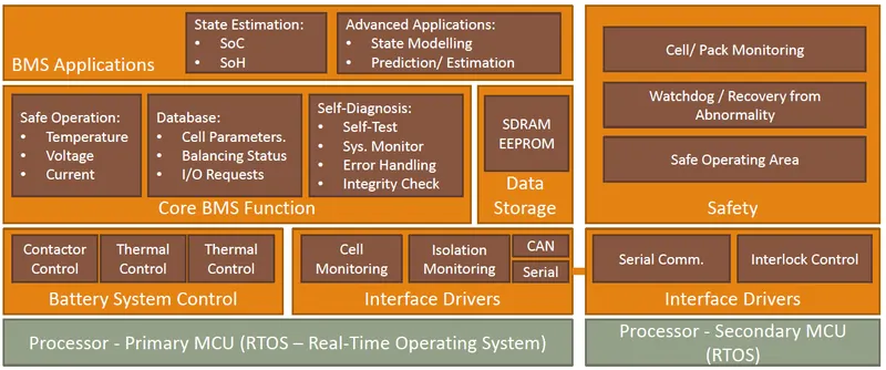
A battery management system (BMS) is any electronic system that manages a rechargeable battery (cell or battery pack), such as by protecting the battery from operating outside its safe operating area, monitoring its state, calculating secondary data, reporting that data, controlling its environment, authenticating it and / or balancing it. Typical BMS design is shown below:
A battery pack built together with a battery management system with an external communication data bus is a smart battery pack. A smart battery pack must be charged by a smart battery charger.
BATTERY MANAGEMENT SYSTEM MODEL
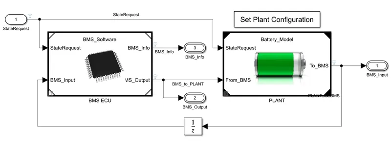
The simulink project model is helpful to study the dynamic behaviour of cells by implementing BMS like functions. This models gives the system level simulation of battery pack. We can use this dynamic models of battery pack to design and test algorithms for Battery Management System before generating production quality C/C++ code and targeting embedded processors. This example Simulink Project includes:
- Battery Cell Characterization
- Detailed Battery Pack Plant Model
- Designing BMS Algorithms
- Code Generation
- Verification & Validation (Requirements + Test Cases)
- Hardware-In-Loop Testing of BMS
The inside system of PLANT and BMS ECU is shown below:
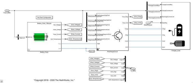
Plant is the hardware of the model, it has the battery pack, Precharge circuit and charge load. The model has two battery model to select from. One is 6 cells in series i.e 6S1P configuration and the other is 6 cells as one module and 16 such modules connected in series i.e 96S1P configuration.
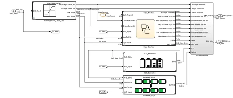
The BMS ECU has State machine which can be thought as the BMS algorithm. Soc estimation, Current power limits block and Balancing logic can also be seen.
BMS TEST HARNESS DASHBOARD:
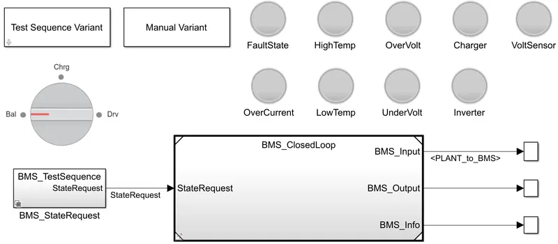
From here we can monitor the fault state and the type of fault, battery state and select test variant of the battery back.
SIMULATION RESULTS:
TEST CASE 1:
TEST CONDITION:

Test case 1 have the condition which is shown above. It has three stages
- Driving
- Charging
- Standby
Battery drains for first 3000 sec which signals that vehicle is in driving mode. After 3000 secs the battery goes into the balancing mode. It stays in balancing mode for 1000 sec and after 1000 secs it is in the charging mode and stays there for 5000 sec. After 5000 sec it then enters is standby mode.
EXPLAINATION/OBSERVATION:
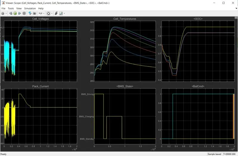
1) From the BMS state plot we can see the intially input tends to disharge the battery which is nothing but a driving condition, then after gap of few seconds the battery enters in charging mode and finally to the standby mode.
2) Cell voltages are different intially which indicates SoC of cells were slightly imbalance at the beginning but starts to get converge after some time as the result of the balancing procedure. The max cell voltage was observed 4.2 V.
3) Pack current responded as per the input and while charging period constant current region can be seen.
4) The temperature traces show a significant discrepancy among the hottest and coldest cell. The reason mainly is the position of cell and symmetry in the module layout in terms of thermal behavior. Cell no. 6 gets significantly hotter than cell no. 1 because it is thermally insulated on one side. The max cell temp. was 316 Kelvin (cell no. 6).
5) The temperatue rise of cell was not of that concern here as it were in the limits but the diffrence between the rise in cell temp. will lead to faster degradation of cell getting hotter frequently. Accordingly this may help us to determine the cooling technique to be implemented.
6) The graph at the top right shows three SoC estimation traces of the same battery cell each performed with the different method. Yellow corresponds to coulomb counting, blue correspnds to UKF (Unscented Kalman Filter) and orange to EKF (Extended Kalman Filter). It can be seen that due to the absence of voltage information in coulomb counting method, it shows quite different estimations than the other two methods.
7) Both kalman filter methods has shown error less results as it takes care of intial SoC and voltage infornation too. EKF slightly out-performs UKF. The SoC drops to 54% for Coulomb counting method and alomost 48% for both kalman filter methods. Battery then enters in charging mode were according to coulomb counting method cell gets charge to 100% while according to Kalman filter method it gets charge up to nearly 92%.
8) Balancing command plot shows the active state of balancing operation for different cells. It seems that initially all the cells needed balancing operation constantly.
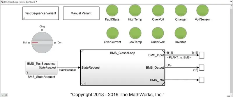
9) From dashboard we can see that there is no indication of any type of fault.
TEST CASE 2
TEST CONDITION:

Test case 2 have the condition which is shown above. It has 2 stages
- Driving
- Charging
For the initial 10000 sec battery in the driving mode. After 10000 secs it enters into charging mode.
EXPLAINATION/OBSERVATION:
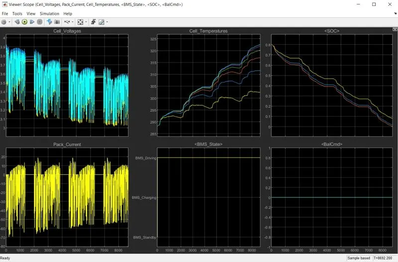
1) We can see from cell voltage plot that cell are already balanced and the also the cell voltages keeps on decreasing. Cell voltage went down to 3.0 V from 3.9 V
2) Pack current responded as per the input. Highest current drawn from pack was 20 A.
3) The temperature trace is high for cell no. 6, Cell no. 6 temperature went upto 322.5 K.
4) SoC went down from 0% to 80%. Again here the different SoC methhod has shown different values. Kalman method especially EKF method was effective in determining right SoC level.
5) According to test condition the pack had two events driving and charging. From BMS state plot we can see that battery never entered in charging mode as the SoC went down to 0% in 8000 secs. From this we can determine the battery capacity needed to meet the driving command.
6) Balancing command was never activated as the test condition had no cell balancing method.
TEST CASE 3
TEST CONDITION:

Test case three has only charging condition
EXPLAINATION/OBSERVATION:
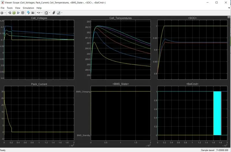
1) From cell voltage and pack current plot we can see that the CCCV method was used to charge the battery. The charging current went upto 30A. The max cell voltage was 4.21 V.
2) Cell temp. intailly rised but later as charging stoped the cell temp. settled down to lower values
3) From BMS state plot we can see that battery was in charging mode from begining. Balancing command was on for this period
4) SoC estimation of three different methods were not same. As per coulomb counting method the SoC is 100% where as per Kalmer methods SoC is approx. 94%.
WHAT IS COULOMB COUNTING AND HOW IT IS USE IN THE BMS MODEL FOR SOC ESTIMATION
COULOMB COUNTING:
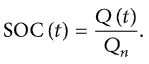
Coulomb counting is used in determining or estimating present state of charge of the battery. In general, the SOC of a battery is defined as the ratio of its current capacity (Qt) to the nominal capacity (Qn). The nominal capacity is given by the manufacturer and represents the maximum amount of charge that can be stored in the battery. The SOC can be defined as follows:
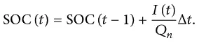
The Coulomb counting method measures the discharging current of a battery and integrates the discharging current over time in order to estimate SOC. Coulomb counting method is done to estimate the SoC(t), which is estimated from the discharging current,I(t), and previously estimated SOC values, SoC(t-1) . SOC is calculated by the following equation:
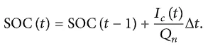
To improve the Coulomb counting method, a new technique called modified Coulomb counting method is proposed. The modified Coulomb counting method uses the corrected current to improve the accuracy of estimation.
The corrected current is the function of discharging current. There is a quadratic relationship between the corrected current and discharging current of battery. By practice of experimental data, corrected current is calculated by the following form:

where k2, k1 and k0 and are constant values obtained from the practice experimental data.
In modified Coulomb counting method, SOC is calculated by the following equation:
The experimental results show that the accuracy of the modified Coulomb counting method is superior to the conventional Coulomb counting method.
IMPLEMENTATION OF COULOMB COUNTING IN MODEL:
The following block accounts for the SoC estimastion in BMS model.
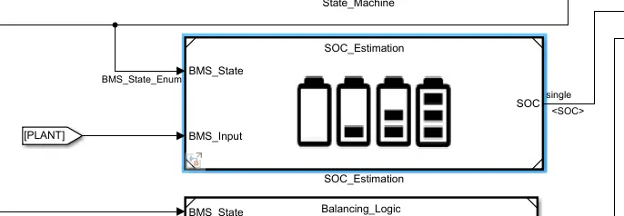

Upon openining subsystem we finally reach the block which implements coulomb counting method.
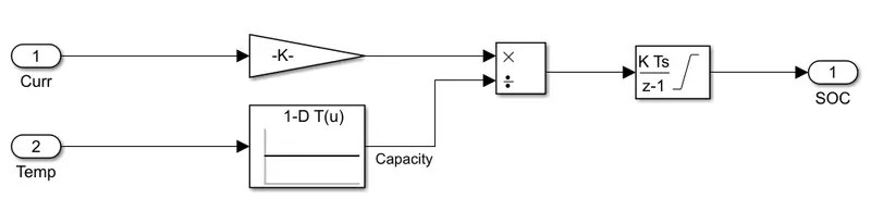
WORKING/IMPLEMENTATION
- Current leaving the cell enters Coulomb counting block.
- The gain block muliplies the current with (1/3600), which is basically converting the current from ampere to Ampere hour.
- As we know that temperature effects the currentand this effect is accounted using 1-D Look up table. Look up table here performs 1-dimensional interpolated table lookup including index searches.
- Divide block then finally characterizes the effect of temerature on current.
- The Coulomb counting method measures the discharging current of a battery and integrates the discharging current over time in order to estimate SOC. This job is done by the integrator block.
- Here Discrete-Time integrator block is used in place of the Integrator block to create a purely discrete model.