Project 1- Traffic Jam Assistant Feature
Traffic Jam Assistant Feature
About Tarffic jam assist feature
Traffic Jam Assist can assist you to in driving in highway traffic jams up to 60 km/h while the host vehicle automatically follows the vehicle ahead. The latest forward-looking radar and camera technology helps sense traffic and the road ahead. Fused data from both sensors is used to help adapt the vehicle speed to the speed of the vehicle ahead, with Stop-and-Go functionality. Based on optical detection of lane markings, the vehicle is centered within the occupied lane.
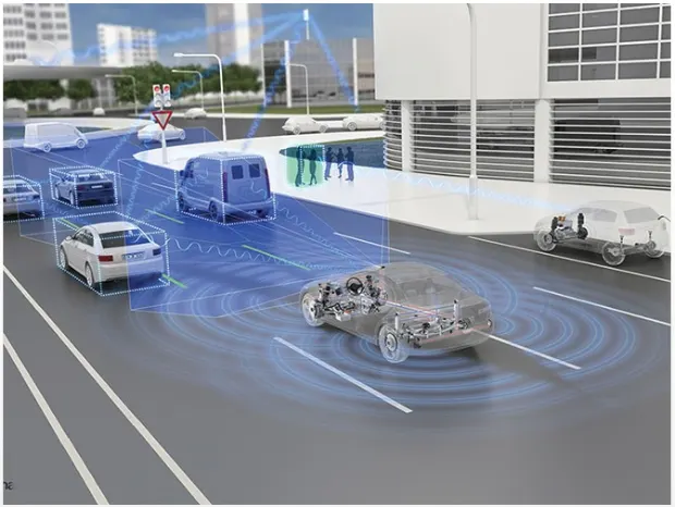
Advantages:
- Optional front corner radars help to improve detection of vehicles cutting in.
- The driver is required to monitor both surrounding traffic and system status and can override the system at anytime (SAE level 2 automation).
- Traffic Jam Assist’s longitudinal, Stop-and-Go control function can manage vehicle speed and help maintain safe distance to the leading vehicle; actuation is performed by ZF’s high-performance electronicaly controlled braking systems or integrated brake control in the case of vacuum-less braking systems.
- The lateral control function can help maintain vehicle position in the lane; actuation is performed by ZF’s well-established, high-bandwidth belt drive or column drive electric powered steering products
- Helps dramatically reduce the efforts and stress of highway driving in congested traffic
- Helps enhance vehicle and occupant safety
- Supports collision mitigation or even collision avoidance to help improve road safety
Developement of Simulink model:
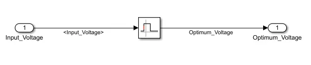
Requirement No 1:
- Input Signal “Input_Voltage” is compared against voltage values “VOLTAGE_MINIMUM_RANGE” & “VOLTAGE_MAXIMUM_RANGE”.
- Incoming input signal “Input_Voltage” must be greater than – equal to “VOLTAGE_MINIMUM_RANGE” and less than – equal to “VOLTAGE_MAXIMUM_RANGE”.
- Output signal from here is “Optimum_Voltage” which will be one of the inputs to the subsystem “DisplayUnit”.
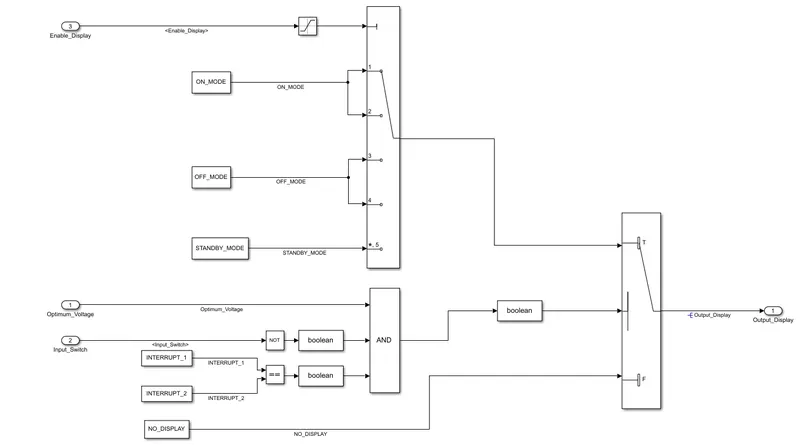
Requirement No 2 (DisplayUnit Subsystem):
- Input Signals are “Optimum_Voltage”, “Input_Switch”,“Enable_Display”. Signal “Enable_Display” must be saturated between the range 0 – 7. Output signal from the subsystem is “Output_Display”.
- Input Signal “Enable_Display” is compared against pre – defined set of values in a multiport switch. Total data ports in the multiport switch is 5.
- Multiport switch inputs 1 & 2 is connected to calibration signal “ON_MODE”, Multiport switch inputs 3 & 4 is connected to calibration signal “OFF_MODE” while Multiport switch input 5 is connected to calibration signal “STANDBY_MODE”.
- The output from Multiport switch is connected to the first input port of the Switch block. The third input port of the Switch block is connected to the calibration signal “NO_DISPLAY”.
- Meanwhile NOT value of input signal “Input_Switch” is compared in an AND gate against input signal “Optimum_Voltage” and the output from comparing if calibration signals “INTERRUPT_1” & “INTERRUPT_2” are equal. The output of the AND gate is the second input of the switch block.
- The output from the switch block is “Output_Display”.
Systemizing the above blocks:
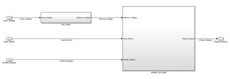
Final Simulink model:
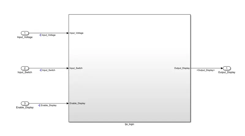
Creation of sldd file:
Our model uses the following data. We have created a simulink data dictionary of it.
Input Signals:
|
Name of the Signal |
Data Type |
Range |
|
Input_Voltage |
uint8 |
0 - 255 |
|
Input_Switch |
boolean |
0 – 1 |
|
Enable_Display |
uint8 |
0 - 255 |
Output Signal:
|
Name of the Signal |
Data Type |
Range |
|
Output_Display |
uint8 |
0 - 255 |
Calibration Signals:
|
Name of the Signal |
Data Type |
Range |
Initial Value |
|
VOLTAGE_MINIMUM_RANGE |
uint8 |
0 – 255 |
30 |
|
VOLTAGE_MAXIMUM_RANGE |
uint8 |
0 – 255 |
50 |
|
OFF_MODE |
uint8 |
0 – 255 |
2 |
|
ON_MODE |
uint8 |
0 – 255 |
1 |
|
STANDBY_MODE |
uint8 |
0 – 255 |
3 |
|
INTERRUPT_1 |
boolean |
0 – 1 |
1 |
|
INTERRUPT_2 |
boolean |
0 - 1 |
1 |
|
NO_DISPLAY |
uint8 |
0 – 255 |
0 |
Local Signal:
|
Name of the Signal |
Data Type |
Range |
|
Optimum_Voltage |
boolean |
0 - 1 |
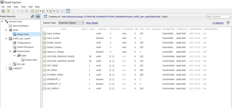
Model Advisor check:
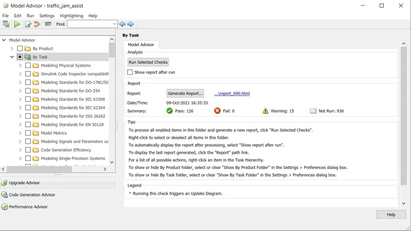
Upon performing model advisor check you can see that or model have 0 fails with 15 warnings.
Code generation:
Selecting ert.tlc embedded coder as code generation profile.
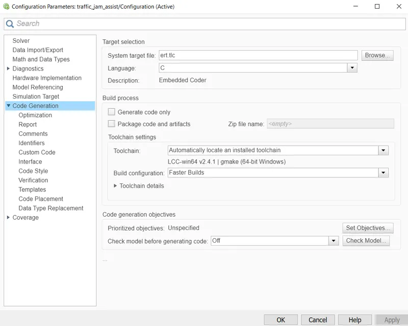
Generated code:
/*
 * File: traffic_jam_assist.c
 *
 * Code generated for Simulink model 'traffic_jam_assist'.
 *
 * Model version                  : 1.3
 * Simulink Coder version         : 9.3 (R2020a) 18-Nov-2019
 * C/C++ source code generated on : Sat Oct  9 17:24:07 2021
 *
 * Target selection: ert.tlc
 * Embedded hardware selection: Intel->x86-64 (Windows64)
 * Code generation objectives: Unspecified
 * Validation result: Not run
 */

#include "traffic_jam_assist.h"
#include "traffic_jam_assist_private.h"

/* Exported block signals */
uint8_T Output_Display;                /* '<S2>/Switch' */

/* Exported data definition */

/* ConstVolatile memory section */
/* Definition for custom storage class: ConstVolatile */
const volatile boolean_T INTERRUPT_1 = 1;/* Referenced by: '<S2>/Constant3' */
const volatile boolean_T INTERRUPT_2 = 1;/* Referenced by: '<S2>/Constant4' */
const volatile uint8_T NO_DISPLAY = 0U;/* Referenced by: '<S2>/Constant5' */
const volatile uint8_T OFF_MODE = 2U;  /* Referenced by: '<S2>/Constant1' */
const volatile uint8_T ON_MODE = 1U;   /* Referenced by: '<S2>/Constant' */
const volatile uint8_T STANDBY_MODE = 3U;/* Referenced by: '<S2>/Constant2' */
const volatile uint8_T VOLTAGE_MAXIMUM_RANGE = 50U;/* Referenced by: '<S4>/Upper Limit' */
const volatile uint8_T VOLTAGE_MINIMUM_RANGE = 30U;/* Referenced by: '<S4>/Lower Limit' */

/* Real-time model */
RT_MODEL_traffic_jam_assist_T traffic_jam_assist_M_;
RT_MODEL_traffic_jam_assist_T *const traffic_jam_assist_M =
  &traffic_jam_assist_M_;

/* Model step function */
void traffic_jam_assist_step(void)
{
  uint8_T tmp;

  /* Switch: '<S2>/Switch' incorporates:
   *  Constant: '<S2>/Constant3'
   *  Constant: '<S2>/Constant4'
   *  Constant: '<S2>/Constant5'
   *  Constant: '<S4>/Lower Limit'
   *  Constant: '<S4>/Upper Limit'
   *  Inport: '<Root>/Input_Switch'
   *  Inport: '<Root>/Input_Voltage'
   *  Logic: '<S2>/AND'
   *  Logic: '<S2>/NOT'
   *  Logic: '<S4>/AND'
   *  RelationalOperator: '<S2>/Equal'
   *  RelationalOperator: '<S4>/Lower Test'
   *  RelationalOperator: '<S4>/Upper Test'
   */
  if ((VOLTAGE_MINIMUM_RANGE <= Input_Voltage) && (Input_Voltage <=
       VOLTAGE_MAXIMUM_RANGE) && (!Input_Switch) && (INTERRUPT_1 == INTERRUPT_2))
  {
    /* Saturate: '<S2>/Saturation' incorporates:
     *  Inport: '<Root>/Enable_Display'
     */
    if (Enable_Display < 7) {
      tmp = Enable_Display;
    } else {
      tmp = 7U;
    }

    /* End of Saturate: '<S2>/Saturation' */

    /* MultiPortSwitch: '<S2>/Multiport Switch' incorporates:
     *  Constant: '<S2>/Constant'
     *  Constant: '<S2>/Constant1'
     *  Constant: '<S2>/Constant2'
     */
    switch (tmp) {
     case 1:
      Output_Display = ON_MODE;
      break;

     case 2:
      Output_Display = ON_MODE;
      break;

     case 3:
      Output_Display = OFF_MODE;
      break;

     case 4:
      Output_Display = OFF_MODE;
      break;

     default:
      Output_Display = STANDBY_MODE;
      break;
    }

    /* End of MultiPortSwitch: '<S2>/Multiport Switch' */
  } else {
    Output_Display = NO_DISPLAY;
  }

  /* End of Switch: '<S2>/Switch' */
}

/* Model initialize function */
void traffic_jam_assist_initialize(void)
{
  /* (no initialization code required) */
}

/* Model terminate function */
void traffic_jam_assist_terminate(void)
{
  /* (no terminate code required) */
}

/*
 * File trailer for generated code.
 *
 * [EOF]
 */
Hence we have implemented the logic for traffic jam display in a simulink model, created sldd file to store variable and define signal seperately, selected embedded coder as code generation profile and finally generated the c-code of the model.