Week 9 Challenge
AIM/OBJECTIVE:
- Energy management strategy model with battery, UC and fuel cell for the positive power and distributing the power demand among these components.
- Simulation and o/p of the model as power request from UC, fuel cell and battery.
About Energy management strategy (EMS):
The vehicle industry is experiencing a technological revolution in the powertrains of vehicles. A hybrid electric vehicle (HEV) is an effective choice to solve the problems of the low energy density of a power battery and the short driving distance of an electric vehicle (EV).
Different configurations of HEVs have different control strategies, production costs, and applicable conditions. However, for any configuration, the ultimate goal is to achieve the comprehensive optimization of the efficiency of the engine and the motor so as to improve the vehicle’s performance parameters such as economy, emissions, and durability. The procedure of realizing the goal is commonly called an energy management strategy (EMS).
In order to optimize the performance of fuel cells and reduce fuel consumption, the best control solution is to power a vehicle with both fuel cell and battery. To model the hybrid powertrains behavior, a simulation program has been made and implemented in matlab/simulink. In particular, the fuel cell type is selected as proton-exchange fuel cell and the battery is lead-acid battery. The fuel cell provides the normal required power for electric vehicles running, whereas the battery model also accounts for the charge/discharge efficiency.
The hybrid powertrains is equipped with an energy management system. During acceleration, power is provided by the storage battery discharging, while during deceleration the battery is recharged. The control strategies assume charge maintaining operation of the battery, and the fuel cell system has to work around its maximum efficiency. The feasibility for energy management is proved by simulation experiment.
Steps to build model:
1. Torque is converted to power first
2. Positive power and negative power are seperated.
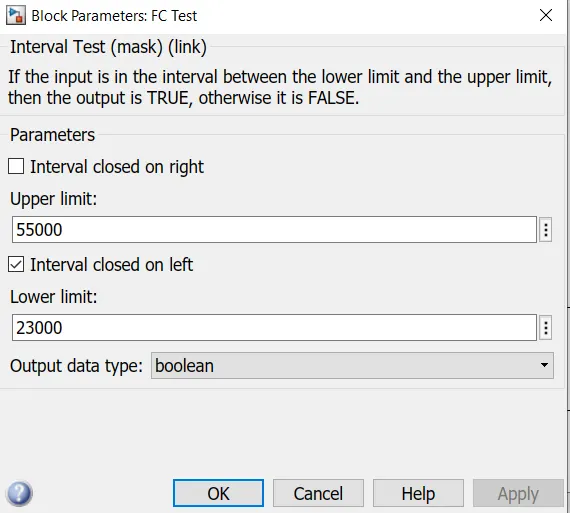
3. Positive power is categorized between low medium and high values.
- Low: Below 23 kW (Batt.)
- Medium: 23 kW - 55 kW (FC)
- High: Above 55 kW (UC)
4. Then an appropriate source is chosen.
5. Negative power is regeneration (Power can go the battery or UC)
6. For positive power, some fail safe strategy needs to be implemented, if SoC is low and battery or UC can't supply power then FC should be used.
Model:
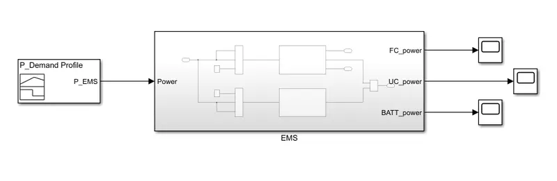
Inside view:
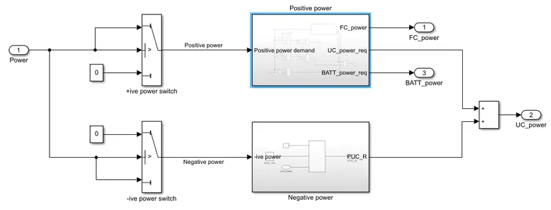
Positive power:
In working of model section we will see its actual implmentation and its working too. If we make Flow chart of logic first it will help us to understand the EMS block.
Working of model:
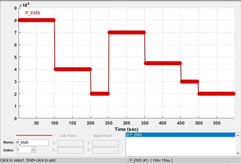
1. The input to the block is power. We have created the power demand profile using signal builder which in turn reads data from excel sheet.
2. This power gets seperated as positive or negative which is done using a simple switch block
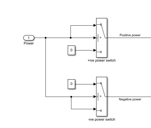
3. Here we are only simulating the model for positive power. This positive power goes inside the positive power block which then categorized as:
- Low: Below 23 kW (Batt.)
- Medium: 23 kW - 55 kW (FC)
- High: Above 55 kW (UC)
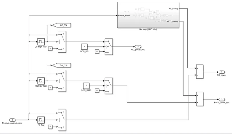
Inside view of positive power block:
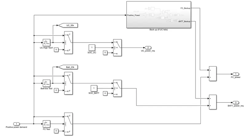
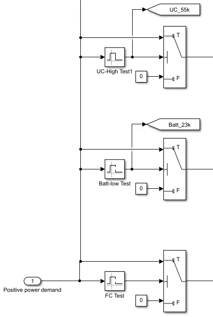
4. This Categorization is achieved using interval block. Its implementation and interval block setting is shown below:
FC, UC and Batt Test block (interval block) settings:
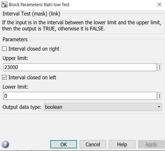
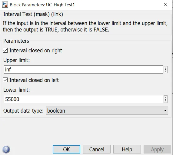
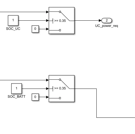
5. With the help of switch block we make the respective demand to energy sources by having a check on SoC level. If SoC of UC or Batt is below 0.35 value then it is restricted to provide the energy to the system. If every thing is fine and there is no chance of failure then this our main Simulink model part. Its implementation is shown below:
6. Now what if UC or batt SoC is low and we still want our vehicle to move a distance. For that we have implemented fail strategy:
Here OR and AND blocks are used to meet the require logic. If either of UC test or batt test is high the and the SoC of UC is low then we have 1 as our output else either of any case is zero our o/p will be zero too. If batt SoC is low then it outputs one and FC has to supply the power to the vehicle. If batt SoC is high then we prefer batt to supply power rather than FC. The exact implemetation is shown below:
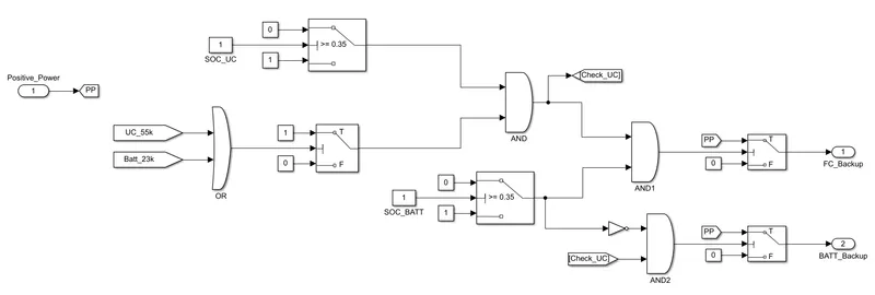
NOT block is used here to have our batt SoC check output as one because we are giving 0 as output when SoC of Batt is High which in turn gets AND operated with output of UC_SoC and UC test or batt test.
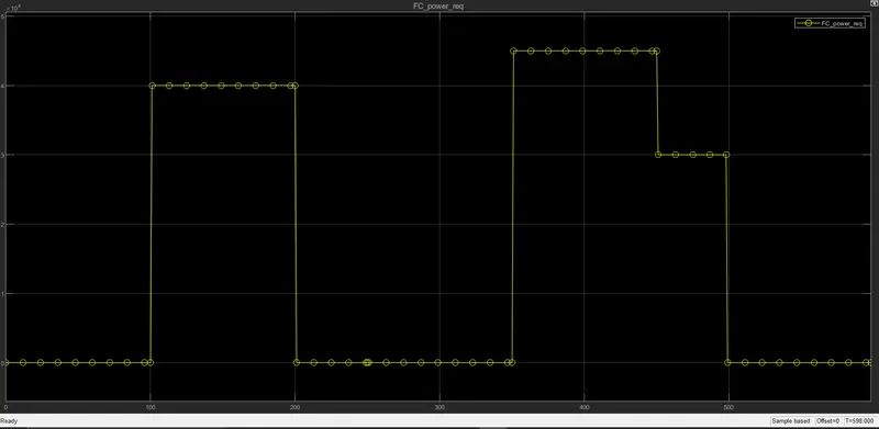
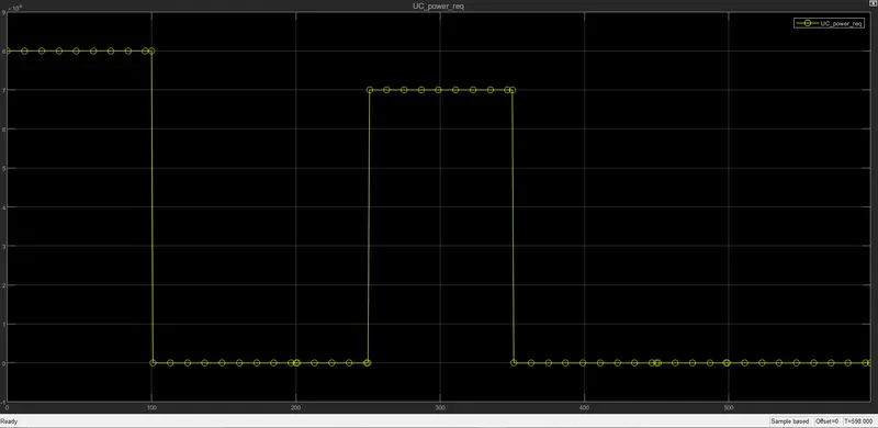
Simulation Results:
FC power request:
UC power request:
Batt power request:
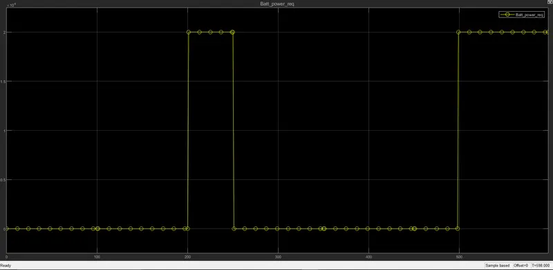
Upon observing the results it is concluded that model did work as per our logic and the no errors were observed durig the simulation of model. For further evaluation model files have been attatched.