ADAPTIVE CRUISE CONTROL
PROJECT ADAPTIVE CRUISE CONTROL
AIM: To develop Simulink model for Adaptive cruise control logic, create and define data in Simulink data dictionary, perform model advisor check and generate c-code using simulink platform.
Brief Overview of ACC (Adaptive cruise control):
Adaptive cruise control (ACC) is an intelligent form of cruise control that slows down and speeds up automatically to keep pace with the car in front of you. The driver sets the maximum speed — just as with cruise control — then a radar sensor watches for traffic ahead, locks on to the car in a lane, and instructs the car to stay 2, 3, or 4 seconds behind the person car ahead of it (the driver sets the follow distance, within reason). ACC is now almost always paired with a pre-crash system that alerts you and often begins braking. ACC is ideal for stop-and-go traffic and rush hour commuting that swings from 60 mph to a standstill.
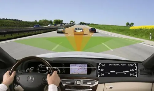
Using ACC
To use adaptive cruise control, you start the same as you would with standard cruise control. The driver turns ACC on, accelerates to the desired speed, then presses the “Set” button. It’s then possible to tweak the “+” and “-” buttons to raise or lower the speed, typically by in 1 or 5 mph increments. Lastly, the driver can set the desired gap behind the next car, most commonly by pressing a button to cycle among short, medium, and long following distances. Some automakers show icons with 1, 2 or 3 distance bars between two vehicle icons. Others, such as Merecedes-Benz, show the following distance in feet, though it’s really in seconds of following gap translated to feet — for example, 200 feet of following distance at 60 mph (88 feet per second) is about 3 seconds.
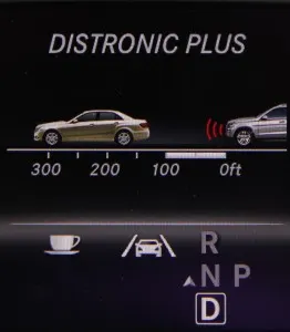
An indicator in the instrument panel or head-up display shows a car icon and often what looks like converging-at-infinity lines, indicating the roadway. When radar detects a car ahead, a second car icon appears or the lone car icon changes color.
When you’re just starting out in a newly acquired car with ACC, start with the longest following distance. If you set the closest following distance, you’ll get nervous if the following distance seems to get dangerously close and you’re not sure if ACC is actually working. Most likely it is working and the driver may have lightly brushed the brake pedal, didn’t realize it, and now ACC is available but not engaged.
Description of model and its development
Requirement 1– Lead Vehicle:
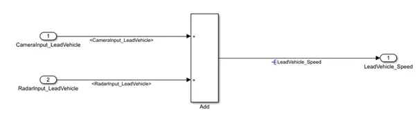
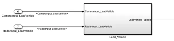
- Lead Vehicle is a vehicle which is driving in the road ahead of our drive vehicle. Two input signals (Signal Name: CameraInput_LeadVehicle & RadarInput_LeadVehicle).
- Ideally sensor fusion techniques will be deployed to process & analyze data from camera & radar. For complexity reasons, let’s not adapt to any such algorithms.
- We can simply add both the radar & camera inputs & the corresponding output is read as Speed profile output (Signal Name: LeadVehicle_Speed).
- Speed data of the lead vehicle is critical in implementing the Adaptive Cruise Control algorithm.
Making subystem of it:
Requirement 2 – Drive Vehicle:
- Drive Vehicle is the vehicle driven by the user & this is the vehicle which has ACC algorithm in it.
- Like the Lead Vehicle, Drive Vehicle algorithm also has 2 input signals (Signal Name: CameraInput_DriveVehicle, RadarInput_DriveVehicle) & one signal coming as an Input to this subsystem (Signal Name: Acceleration_Mode) – three inputs into this requirement in total.
- Like the above requirement, sensor fusion techniques will also be deployed here, for complexity reasons we are ignoring them.
- Two output signals come from this subsystem (Signal Name: DriveVehicle_Speed & LeadVehicle_Detected).
- Signal DriveVehicle_Speed is summation of three input signals mentioned above & LeadVehicle_Detected is renamed from Input Signal RadarInput_DriveVehicle by mere use of Signal Conversion block.
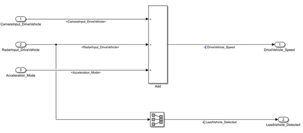
Making subsystem of it:
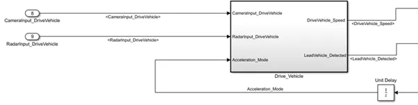
Requirement 3 – Adaptive Cruise Control Algorithm:
- Adaptive Cruise Control feature has 3 major modes of operation: OFF Mode, STANDBY Mode & ON Mode. This particular requirement has to be implemented as state machine logic in Simulink.
- The input signals to this state machine system are (Signal Name: Time_Gap, Set_Speed, Set_Gap, CruiseSwitch, SetSwitch).
- Also, the output signals (Signal Name: DriveVehicle_Speed & LeadVehicle_Detected) from requirement-2 is fed back as an input signal into this state machine block.
- Additionally, output signal (Signal Name: LeadVehicle_Speed) from requirement-1 is given as an input signal to this state machine block as well.
- Output from this subsystem is a signal (Signal Name: Acceleration_Mode) which governs the vehicular speed of the drive vehicle which automatically adjusts its speed & velocity to match the lead vehicle.
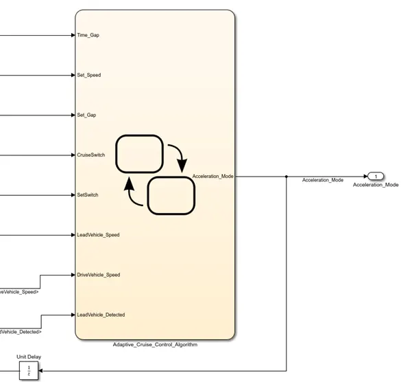
Requirement 3a – ACC OFF MODE state logic:
- This is the default state inside state machine logic. Output signal Acceleration_Mode is at value 0 in this state.
- This state is governed by input signal CruiseSwitch.
- If CruiseSwitch is equal to 1, state ACC STANDBY mode will get activated. If CruiseSwitch is equal to 0, state ACC OFF mode will get activated, from either ACC ON mode or ACC STANDBY mode
Requirement 3b – ACC STANDBY MODE state logic:
- This is the second activated state inside state machine logic. Output signal Acceleration_Mode is at value 1 in this state.
- This state is governed by both input signals CruiseSwitch & SetSwitch.
- If CruiseSwitch is equal to 1, state ACC STANDBY mode will get activated. If CruiseSwitch is equal to 0, state ACC OFF mode will get activated, from either ACC ON mode or ACC STANDBY mode
- If SetSwitch is equal to 1, state ACC ON mode will get activated. If SetSwitch is equal to 0, state ACC STANDBY mode will get activated.
Requirement 3c – ACC ON MODE state logic:
This state will be activated when input signal SetSwitch is equal to 1. There are 6 sub states to this state logic: They are:
- LeadVehicle_Detected_Follow (Default)
- LeadVehicle_Not_Detected
- LeadVehicle_Detected_Resume
- LeadVehicle_Not_Detected_Resume
- LeadVehicle_Speed_lessthan_Set_Speed
Requirement 3c (i) – LeadVehicle_Detected_Follow (ACC ON MODE):
- This is the default sub state inside ACC ON MODE state. Output signal Acceleration_Mode is equal to 2.
- Condition to transit from LeadVehicle_Detected_Follow to LeadVehicle_Not_Detected; Input signal condition LeadVehicle_Detected == 0.
- Condition to transit from LeadVehicle_Detected_Follow to LeadVehicle_Speed_lessthan_Set_Speed; Input Signals condition (LeadVehicle_Detected == 1) && (LeadVehicle_Speed < Set_Speed) || (Time_Gap < Set_Gap).
Requirement 3c (ii) – LeadVehicle_Not_Detected (ACC ON MODE):
- Output signal Acceleration_Mode is equal to 1.
- Condition to transit from LeadVehicle_Not_Detected to LeadVehicle_Detected_Follow; Input signals condition [(LeadVehicle_Detected==1) && (DriveVehicle_Speed == Set_Speed) && (LeadVehicle_Speed >= Set_Speed) && (Time_Gap >= Set_Gap)]
- Condition to transit from LeadVehicle_Not_Detected to LeadVehicle_Speed_lessthan_Set_Speed; Input signals condition [(LeadVehicle_Detected == 1) && (LeadVehicle_Speed < Set_Speed) || (Time_Gap < Set_Gap)]
Requirement 3c (iii) – LeadVehicle_Detected_Resume (ACC ON MODE):
- Output signal Acceleration_Mode is equal to 3.
- Condition to transit from LeadVehicle_Detected_Resume to LeadVehicle_Detected_Follow; Input signals condition [(DriveVehicle_Speed == Set_Speed) && (LeadVehicle_Speed >= Set_Speed) && (Time_Gap >= Set_Gap)]
- Condition to transit from LeadVehicle_Detected_Resume to LeadVehicle_Not_Detected_Resume; Input signal condition LeadVehicle_Detected==0.
- Condition to transit from LeadVehicle_Detected_Resume to LeadVehicle_Speed_equal_Set_Speed; Input Signal condition [(DriveVehicle_Speed < Set_Speed) && (LeadVehicle_Speed > DriveVehicle_Speed) && (Time_Gap >= Set_Gap)]
Requirement 3c (iv) - LeadVehicle_Not_Detected_Resume (ACC ON MODE):
- Output signal Acceleration_Mode is equal to 1.
Requirement 3c (v) - LeadVehicle_Speed_lessthan_Set_Speed (ACC ON MODE):
- Output signal Acceleration_Mode is equal to 4.
- Condition to transit from LeadVehicle_Speed_lessthan_Set_Speed to LeadVehicle_Not_Detected; Input signal condition [(LeadVehicle_Detected == 0) && (DriveVehicle_Speed == Set_Speed)]
- Condition to transit from LeadVehicle_Speed_lessthan_Set_Speed to LeadVehicle_Speed_equal_Set_Speed; Input signals condition [((LeadVehicle_Speed*1.25>=DriveVehicle_Speed) && (LeadVehicle_Speed * 0.75<=DriveVehicle_Speed)) && (DriveVehicle_Speed < Set_Speed) && ((Time_Gap<=1.25*Set_Gap) && (Time_Gap >=0.75*Set_Gap))]
Requirement 3c (vi) - LeadVehicle_Speed_equal_Set_Speed (ACC ON MODE):
- Output signal Acceleration_Mode is equal to 5.
- Condition to transit from LeadVehicle_Speed_equal_Set_Speed to LeadVehicle_Not_Detected_Resume; Input signal conditions is [(LeadVehicle_Detected == 0) || (DriveVehicle_Speed <= Set_Speed)]
- Condition to transit from LeadVehicle_Speed_equal_Set_Speed to LeadVehicle_Detected_Resume; Input signal conditions [(DriveVehicle_Speed < Set_Speed) && (LeadVehicle_Speed > DriveVehicle_Speed) || (Time_Gap >= Set_Gap)]
- Condition to transit from LeadVehicle_Speed_equal_Set_Speed to LeadVehicle_Speed_lessthan_Set_Speed; Input signals conditions [(LeadVehicle_Speed<Set_Speed) && (LeadVehicle_Speed<DriveVehicle_Speed) || (Time_Gap==0.75*Set_Gap)]
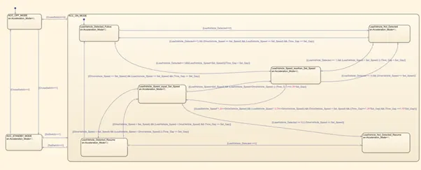
As we have created all the subsytems with there respective requirements, this what our model looks like. You will get to see the above blocks and logics as you go through the respective subystem.
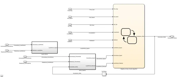
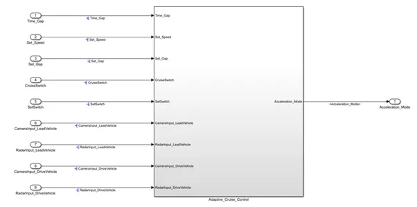
Creating and defining data in Simulink data dictionary:
To create SLDD follow this path: Right click on model<
These are the datas we want to define:
Signals & Calibration Data List:
|
Signal / Calibration Name |
Signal Type |
Data Type |
Dimension |
Min |
Max |
Initial Value |
Units |
|
CameraInput_LeadVehicle |
Input |
Uint8 |
1 |
0 |
255 |
- |
- |
|
RadarInput_LeadVehicle |
Input |
Uint8 |
1 |
0 |
255 |
- |
- |
|
CameraInput_DriveVehicle |
Input |
Uint8 |
1 |
0 |
255 |
- |
- |
|
RadarInput_DriveVehicle |
Input |
Uint8 |
1 |
0 |
255 |
- |
- |
|
Time_Gap |
Input |
Uint8 |
1 |
0 |
255 |
- |
- |
|
Set_Speed |
Input |
Uint8 |
1 |
0 |
255 |
- |
- |
|
Set_Gap |
Input |
Uint8 |
1 |
0 |
255 |
- |
- |
|
CruiseSwitch |
Input |
Boolean |
1 |
0 |
1 |
- |
- |
|
SetSwitch |
Input |
Boolean |
1 |
0 |
1 |
- |
- |
|
Acceleration_Mode |
Output |
Uint8 |
1 |
0 |
255 |
- |
- |
|
LeadVehicle_Speed |
Output |
Uint8 |
1 |
0 |
255 |
- |
- |
|
DriveVehicle_Speed |
Output |
Uint8 |
1 |
0 |
255 |
- |
- |
|
LeadVehicle_Detected |
Output |
Uint8 |
1 |
0 |
255 |
- |
- |
Data added in Sldd file:
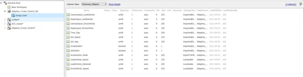
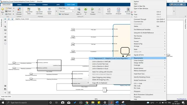
We have also tagged the document stating the requirement of specific blocks: To view requirement follow below fig. and this path implies to every subsystem.
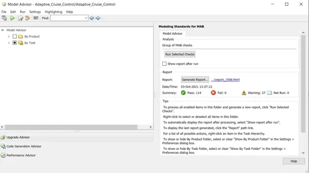
Model advisor check
Generating code:
To generate code, follow exact procedure shown in image below:
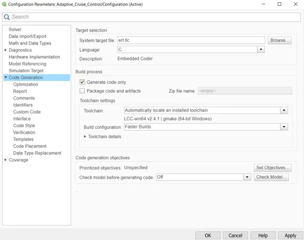
After hitting the build icon code will finally will get generated:
Generated Code:
/*
 * File: Adaptive_Cruise_Control.c
 *
 * Code generated for Simulink model 'Adaptive_Cruise_Control'.
 *
 * Model version                  : 1.12
 * Simulink Coder version         : 9.3 (R2020a) 18-Nov-2019
 * C/C++ source code generated on : Sun Oct  3 21:03:36 2021
 *
 * Target selection: ert.tlc
 * Embedded hardware selection: Intel->x86-64 (Windows64)
 * Code generation objectives: Unspecified
 * Validation result: Not run
 */

#include "Adaptive_Cruise_Control.h"
#include "Adaptive_Cruise_Control_private.h"

/* Named constants for Chart: '/Adaptive_Cruise_Control_Algorithm' */
#define Ada_IN_LeadVehicle_Not_Detected ((uint8_T)3U)
#define Adaptive_Cr_IN_ACC_STANDBY_MODE ((uint8_T)3U)
#define Adaptive_Cru_IN_NO_ACTIVE_CHILD ((uint8_T)0U)
#define Adaptive_Cruise_IN_ACC_OFF_MODE ((uint8_T)1U)
#define Adaptive_Cruise__IN_ACC_ON_MODE ((uint8_T)2U)
#define IN_LeadVehicle_Detected_Follow ((uint8_T)1U)
#define IN_LeadVehicle_Detected_Resume ((uint8_T)2U)
#define IN_LeadVehicle_Not_Detected_Res ((uint8_T)4U)
#define IN_LeadVehicle_Speed_equal_Set_ ((uint8_T)5U)
#define IN_LeadVehicle_Speed_lessthan_S ((uint8_T)6U)

/* Exported data definition */

/* Definition for custom storage class: Localizable */
static uint8_T DriveVehicle_Speed;     /* '/Add' */
static uint8_T LeadVehicle_Detected;   /* '/Signal Conversion' */
static uint8_T LeadVehicle_Speed;      /* '/Add' */

/* Block states (default storage) */
DW_Adaptive_Cruise_Control_T Adaptive_Cruise_Control_DW;

/* External outputs (root outports fed by signals with default storage) */
ExtY_Adaptive_Cruise_Control_T Adaptive_Cruise_Control_Y;

/* Real-time model */
RT_MODEL_Adaptive_Cruise_Cont_T Adaptive_Cruise_Control_M_;
RT_MODEL_Adaptive_Cruise_Cont_T *const Adaptive_Cruise_Control_M =
  &Adaptive_Cruise_Control_M_;

/* Forward declaration for local functions */
static void Adaptive_Cruise_Con_ACC_ON_MODE(void);
real_T rt_roundd_snf(real_T u)
{
  real_T y;
  if (fabs(u) < 4.503599627370496E+15) {
    if (u >= 0.5) {
      y = floor(u + 0.5);
    } else if (u > -0.5) {
      y = u * 0.0;
    } else {
      y = ceil(u - 0.5);
    }
  } else {
    y = u;
  }

  return y;
}

/* Function for Chart: '/Adaptive_Cruise_Control_Algorithm' */
static void Adaptive_Cruise_Con_ACC_ON_MODE(void)
{
  int32_T tmp;
  int32_T tmp_0;
  uint8_T tmp_1;
  uint8_T tmp_2;

  /* Inport: '/SetSwitch' incorporates:
   *  Inport: '/CruiseSwitch'
   */
  /* During 'ACC_ON_MODE': ':6' */
  if (!SetSwitch) {
    /* Transition: ':8' */
    /* Exit Internal 'ACC_ON_MODE': ':6' */
    Adaptive_Cruise_Control_DW.is_ACC_ON_MODE = Adaptive_Cru_IN_NO_ACTIVE_CHILD;
    Adaptive_Cruise_Control_DW.is_c3_Adaptive_Cruise_Control =
      Adaptive_Cr_IN_ACC_STANDBY_MODE;

    /* Outport: '/Acceleration_Mode' */
    /* Entry 'ACC_STANDBY_MODE': ':3' */
    Adaptive_Cruise_Control_Y.Acceleration_Mode = 1U;
  } else if (!CruiseSwitch) {
    /* Transition: ':35' */
    /* Exit Internal 'ACC_ON_MODE': ':6' */
    Adaptive_Cruise_Control_DW.is_ACC_ON_MODE = Adaptive_Cru_IN_NO_ACTIVE_CHILD;
    Adaptive_Cruise_Control_DW.is_c3_Adaptive_Cruise_Control =
      Adaptive_Cruise_IN_ACC_OFF_MODE;

    /* Outport: '/Acceleration_Mode' */
    /* Entry 'ACC_OFF_MODE': ':1' */
    Adaptive_Cruise_Control_Y.Acceleration_Mode = 0U;
  } else {
    switch (Adaptive_Cruise_Control_DW.is_ACC_ON_MODE) {
     case IN_LeadVehicle_Detected_Follow:
      /* Outport: '/Acceleration_Mode' */
      /* Inport: '/Set_Gap' incorporates:
       *  Inport: '/Set_Speed'
       *  Inport: '/Time_Gap'
       */
      Adaptive_Cruise_Control_Y.Acceleration_Mode = 2U;

      /* During 'LeadVehicle_Detected_Follow': ':9' */
      if (LeadVehicle_Detected == 0) {
        /* Transition: ':21' */
        Adaptive_Cruise_Control_DW.is_ACC_ON_MODE =
          Ada_IN_LeadVehicle_Not_Detected;

        /* Outport: '/Acceleration_Mode' */
        /* Entry 'LeadVehicle_Not_Detected': ':13' */
        Adaptive_Cruise_Control_Y.Acceleration_Mode = 1U;
      } else {
        if (((LeadVehicle_Detected == 1) && (LeadVehicle_Speed < Set_Speed)) ||
            (Time_Gap < Set_Gap)) {
          /* Transition: ':16' */
          Adaptive_Cruise_Control_DW.is_ACC_ON_MODE =
            IN_LeadVehicle_Speed_lessthan_S;

          /* Outport: '/Acceleration_Mode' */
          /* Entry 'LeadVehicle_Speed_lessthan_Set_Speed': ':14' */
          Adaptive_Cruise_Control_Y.Acceleration_Mode = 4U;
        }
      }
      break;

     case IN_LeadVehicle_Detected_Resume:
      /* Outport: '/Acceleration_Mode' */
      Adaptive_Cruise_Control_Y.Acceleration_Mode = 3U;

      /* Inport: '/Set_Speed' incorporates:
       *  Inport: '/Set_Gap'
       *  Inport: '/Time_Gap'
       */
      /* During 'LeadVehicle_Detected_Resume': ':19' */
      if ((DriveVehicle_Speed == Set_Speed) && (LeadVehicle_Speed >= Set_Speed) &&
          (Time_Gap >= Set_Gap)) {
        /* Transition: ':22' */
        Adaptive_Cruise_Control_DW.is_ACC_ON_MODE =
          IN_LeadVehicle_Detected_Follow;

        /* Outport: '/Acceleration_Mode' */
        /* Entry 'LeadVehicle_Detected_Follow': ':9' */
        Adaptive_Cruise_Control_Y.Acceleration_Mode = 2U;
      } else if (LeadVehicle_Detected == 0) {
        /* Transition: ':23' */
        Adaptive_Cruise_Control_DW.is_ACC_ON_MODE =
          IN_LeadVehicle_Not_Detected_Res;

        /* Outport: '/Acceleration_Mode' */
        /* Entry 'LeadVehicle_Not_Detected_Resume': ':20' */
        Adaptive_Cruise_Control_Y.Acceleration_Mode = 1U;
      } else {
        if ((DriveVehicle_Speed < Set_Speed) && (LeadVehicle_Speed >
             DriveVehicle_Speed) && (Time_Gap >= Set_Gap)) {
          /* Transition: ':25' */
          Adaptive_Cruise_Control_DW.is_ACC_ON_MODE =
            IN_LeadVehicle_Speed_equal_Set_;

          /* Outport: '/Acceleration_Mode' */
          /* Entry 'LeadVehicle_Speed_equal_Set_Speed': ':24' */
          Adaptive_Cruise_Control_Y.Acceleration_Mode = 5U;
        }
      }
      break;

     case Ada_IN_LeadVehicle_Not_Detected:
      /* Outport: '/Acceleration_Mode' */
      Adaptive_Cruise_Control_Y.Acceleration_Mode = 1U;

      /* Inport: '/Set_Speed' incorporates:
       *  Inport: '/Set_Gap'
       *  Inport: '/Time_Gap'
       */
      /* During 'LeadVehicle_Not_Detected': ':13' */
      if ((LeadVehicle_Detected == 1) && (DriveVehicle_Speed == Set_Speed) &&
          (LeadVehicle_Speed >= Set_Speed) && (Time_Gap >= Set_Gap)) {
        /* Transition: ':17' */
        Adaptive_Cruise_Control_DW.is_ACC_ON_MODE =
          IN_LeadVehicle_Detected_Follow;

        /* Outport: '/Acceleration_Mode' */
        /* Entry 'LeadVehicle_Detected_Follow': ':9' */
        Adaptive_Cruise_Control_Y.Acceleration_Mode = 2U;
      } else {
        if (((LeadVehicle_Detected == 1) && (LeadVehicle_Speed < Set_Speed)) ||
            (Time_Gap < Set_Gap)) {
          /* Transition: ':18' */
          Adaptive_Cruise_Control_DW.is_ACC_ON_MODE =
            IN_LeadVehicle_Speed_lessthan_S;

          /* Outport: '/Acceleration_Mode' */
          /* Entry 'LeadVehicle_Speed_lessthan_Set_Speed': ':14' */
          Adaptive_Cruise_Control_Y.Acceleration_Mode = 4U;
        }
      }
      break;

     case IN_LeadVehicle_Not_Detected_Res:
      /* Outport: '/Acceleration_Mode' */
      Adaptive_Cruise_Control_Y.Acceleration_Mode = 1U;

      /* During 'LeadVehicle_Not_Detected_Resume': ':20' */
      break;

     case IN_LeadVehicle_Speed_equal_Set_:
      /* Outport: '/Acceleration_Mode' */
      Adaptive_Cruise_Control_Y.Acceleration_Mode = 5U;

      /* Inport: '/Set_Speed' incorporates:
       *  Inport: '/Set_Gap'
       *  Inport: '/Time_Gap'
       */
      /* During 'LeadVehicle_Speed_equal_Set_Speed': ':24' */
      if ((LeadVehicle_Detected == 0) || (DriveVehicle_Speed <= Set_Speed)) {
        /* Transition: ':32' */
        Adaptive_Cruise_Control_DW.is_ACC_ON_MODE =
          IN_LeadVehicle_Not_Detected_Res;

        /* Outport: '/Acceleration_Mode' */
        /* Entry 'LeadVehicle_Not_Detected_Resume': ':20' */
        Adaptive_Cruise_Control_Y.Acceleration_Mode = 1U;
      } else if (((DriveVehicle_Speed < Set_Speed) && (LeadVehicle_Speed >
                   DriveVehicle_Speed)) || (Time_Gap >= Set_Gap)) {
        /* Transition: ':33' */
        Adaptive_Cruise_Control_DW.is_ACC_ON_MODE =
          IN_LeadVehicle_Detected_Resume;

        /* Outport: '/Acceleration_Mode' */
        /* Entry 'LeadVehicle_Detected_Resume': ':19' */
        Adaptive_Cruise_Control_Y.Acceleration_Mode = 3U;
      } else {
        if (((LeadVehicle_Speed < Set_Speed) && (LeadVehicle_Speed <
              DriveVehicle_Speed)) || ((int32_T)rt_roundd_snf(0.75 * (real_T)
              Set_Gap) == Time_Gap)) {
          /* Transition: ':34' */
          Adaptive_Cruise_Control_DW.is_ACC_ON_MODE =
            IN_LeadVehicle_Speed_lessthan_S;

          /* Outport: '/Acceleration_Mode' */
          /* Entry 'LeadVehicle_Speed_lessthan_Set_Speed': ':14' */
          Adaptive_Cruise_Control_Y.Acceleration_Mode = 4U;
        }
      }
      break;

     default:
      /* Outport: '/Acceleration_Mode' */
      Adaptive_Cruise_Control_Y.Acceleration_Mode = 4U;

      /* Inport: '/Set_Speed' */
      /* During 'LeadVehicle_Speed_lessthan_Set_Speed': ':14' */
      if ((LeadVehicle_Detected == 0) && (DriveVehicle_Speed == Set_Speed)) {
        /* Transition: ':26' */
        Adaptive_Cruise_Control_DW.is_ACC_ON_MODE =
          Ada_IN_LeadVehicle_Not_Detected;

        /* Outport: '/Acceleration_Mode' */
        /* Entry 'LeadVehicle_Not_Detected': ':13' */
        Adaptive_Cruise_Control_Y.Acceleration_Mode = 1U;
      } else {
        tmp = (int32_T)rt_roundd_snf((real_T)LeadVehicle_Speed * 1.25);

        /* Inport: '/Set_Gap' */
        tmp_0 = (int32_T)rt_roundd_snf(1.25 * (real_T)Set_Gap);
        if (tmp < 256) {
          tmp_1 = (uint8_T)tmp;
        } else {
          tmp_1 = MAX_uint8_T;
        }

        if (tmp_0 < 256) {
          tmp_2 = (uint8_T)tmp_0;
        } else {
          tmp_2 = MAX_uint8_T;
        }

        /* Inport: '/Time_Gap' incorporates:
         *  Inport: '/Set_Gap'
         */
        if ((tmp_1 >= DriveVehicle_Speed) && ((int32_T)rt_roundd_snf((real_T)
              LeadVehicle_Speed * 0.75) <= DriveVehicle_Speed) &&
            (DriveVehicle_Speed < Set_Speed) && (Time_Gap <= tmp_2) && (Time_Gap
             >= (int32_T)rt_roundd_snf(0.75 * (real_T)Set_Gap))) {
          /* Transition: ':31' */
          Adaptive_Cruise_Control_DW.is_ACC_ON_MODE =
            IN_LeadVehicle_Speed_equal_Set_;

          /* Outport: '/Acceleration_Mode' */
          /* Entry 'LeadVehicle_Speed_equal_Set_Speed': ':24' */
          Adaptive_Cruise_Control_Y.Acceleration_Mode = 5U;
        }
      }
      break;
    }
  }

  /* End of Inport: '/SetSwitch' */
}

/* Model step function */
void Adaptive_Cruise_Control_step(void)
{
  /* Outputs for Atomic SubSystem: '/Lead_Vehicle' */
  /* Sum: '/Add' incorporates:
   *  Inport: '/CameraInput_LeadVehicle'
   *  Inport: '/RadarInput_LeadVehicle'
   */
  LeadVehicle_Speed = (uint8_T)((uint32_T)CameraInput_LeadVehicle +
    RadarInput_LeadVehicle);

  /* End of Outputs for SubSystem: '/Lead_Vehicle' */

  /* Outputs for Atomic SubSystem: '/Drive_Vehicle' */
  /* Sum: '/Add' incorporates:
   *  Inport: '/CameraInput_DriveVehicle'
   *  Inport: '/RadarInput_DriveVehicle'
   *  UnitDelay: '/Unit Delay'
   */
  DriveVehicle_Speed = (uint8_T)((uint32_T)(uint8_T)((uint32_T)
    CameraInput_DriveVehicle + RadarInput_DriveVehicle) +
    Adaptive_Cruise_Control_DW.UnitDelay_DSTATE);

  /* SignalConversion: '/Signal Conversion' incorporates:
   *  Inport: '/RadarInput_DriveVehicle'
   */
  LeadVehicle_Detected = RadarInput_DriveVehicle;

  /* End of Outputs for SubSystem: '/Drive_Vehicle' */

  /* Chart: '/Adaptive_Cruise_Control_Algorithm' incorporates:
   *  Inport: '/CruiseSwitch'
   *  Inport: '/SetSwitch'
   */
  /* Gateway: Adaptive_Cruise_Control/Adaptive_Cruise_Control_Algorithm */
  /* During: Adaptive_Cruise_Control/Adaptive_Cruise_Control_Algorithm */
  if (Adaptive_Cruise_Control_DW.is_active_c3_Adaptive_Cruise_Co == 0U) {
    /* Entry: Adaptive_Cruise_Control/Adaptive_Cruise_Control_Algorithm */
    Adaptive_Cruise_Control_DW.is_active_c3_Adaptive_Cruise_Co = 1U;

    /* Entry Internal: Adaptive_Cruise_Control/Adaptive_Cruise_Control_Algorithm */
    /* Transition: ':2' */
    Adaptive_Cruise_Control_DW.is_c3_Adaptive_Cruise_Control =
      Adaptive_Cruise_IN_ACC_OFF_MODE;

    /* Outport: '/Acceleration_Mode' */
    /* Entry 'ACC_OFF_MODE': ':1' */
    Adaptive_Cruise_Control_Y.Acceleration_Mode = 0U;
  } else {
    switch (Adaptive_Cruise_Control_DW.is_c3_Adaptive_Cruise_Control) {
     case Adaptive_Cruise_IN_ACC_OFF_MODE:
      /* Outport: '/Acceleration_Mode' */
      Adaptive_Cruise_Control_Y.Acceleration_Mode = 0U;

      /* During 'ACC_OFF_MODE': ':1' */
      if (CruiseSwitch) {
        /* Transition: ':4' */
        Adaptive_Cruise_Control_DW.is_c3_Adaptive_Cruise_Control =
          Adaptive_Cr_IN_ACC_STANDBY_MODE;

        /* Outport: '/Acceleration_Mode' */
        /* Entry 'ACC_STANDBY_MODE': ':3' */
        Adaptive_Cruise_Control_Y.Acceleration_Mode = 1U;
      }
      break;

     case Adaptive_Cruise__IN_ACC_ON_MODE:
      Adaptive_Cruise_Con_ACC_ON_MODE();
      break;

     default:
      /* Outport: '/Acceleration_Mode' */
      Adaptive_Cruise_Control_Y.Acceleration_Mode = 1U;

      /* During 'ACC_STANDBY_MODE': ':3' */
      if (!CruiseSwitch) {
        /* Transition: ':5' */
        Adaptive_Cruise_Control_DW.is_c3_Adaptive_Cruise_Control =
          Adaptive_Cruise_IN_ACC_OFF_MODE;

        /* Outport: '/Acceleration_Mode' */
        /* Entry 'ACC_OFF_MODE': ':1' */
        Adaptive_Cruise_Control_Y.Acceleration_Mode = 0U;
      } else {
        if (SetSwitch) {
          /* Transition: ':7' */
          Adaptive_Cruise_Control_DW.is_c3_Adaptive_Cruise_Control =
            Adaptive_Cruise__IN_ACC_ON_MODE;

          /* Entry Internal 'ACC_ON_MODE': ':6' */
          /* Transition: ':50' */
          Adaptive_Cruise_Control_DW.is_ACC_ON_MODE =
            IN_LeadVehicle_Detected_Follow;

          /* Outport: '/Acceleration_Mode' */
          /* Entry 'LeadVehicle_Detected_Follow': ':9' */
          Adaptive_Cruise_Control_Y.Acceleration_Mode = 2U;
        }
      }
      break;
    }
  }

  /* End of Chart: '/Adaptive_Cruise_Control_Algorithm' */

  /* Update for UnitDelay: '/Unit Delay' incorporates:
   *  Outport: '/Acceleration_Mode'
   */
  Adaptive_Cruise_Control_DW.UnitDelay_DSTATE =
    Adaptive_Cruise_Control_Y.Acceleration_Mode;
}

/* Model initialize function */
void Adaptive_Cruise_Control_initialize(void)
{
  /* (no initialization code required) */
}

/* Model terminate function */
void Adaptive_Cruise_Control_terminate(void)
{
  /* (no terminate code required) */
}

/*
 * File trailer for generated code.
 *
 * [EOF]
 */
Conclusion: Hence we have Developed Adaptive Cruise Control feature as per the Requirement Document using MATLAB Simulink and followed all the MBD related processes: Requirement Tagging & Traceability, SLDD creation, Configuration Parameter changes, Model Advisor check & Code Generation.