Week -2
CHALLENGES:
CHALLENGE 1. Make a Simulink model of Doorbell using solenoid block with the following detail:
when the switch is closed the electromagnet receives electrical power from the battery and pulls the metal arm to hit the bell producing sound. Create a situation where the switch is closed for 2 seconds and then released. Observe the physical movement of the plunger.
CHALLANGE 2. Use a thermistor to sense the temperature of a heater & turn on or turn off the fan as per below conditions:
Temperature source: 20 °C from 0 to 10 seconds, 27 °C from 10 to 30 seconds, 23 °C from 30 to 50 seconds
Fan conditions: ON if the temperature above 25 °C, OFF otherwise
CHALLENGE 1
No matter how big, small, easy or complex simulink model we make it is always neccessary to understand the purpose of the model and how its functioning is supposed be,
So the purpose of door bell is to alarm us about someone in the door entrance who wants to meet us. Creating sound is the best thing to do so. We will make that sound by hammering the disc frequently. Below fig helps to achieve the task by using solenoid which is basically an electromagnet, a battery, a switch, metal contactor, hammer (which is attached to iron strip) and a hollow semispherical disc.
What is solenoid: A solenoid is a type of electromagnet, the purpose of which is to generate a controlled magnetic field through a coil wound into a tightly packed helix. The coil can be arranged to produce a uniform magnetic field in a volume of space when an electric current is passed through it.
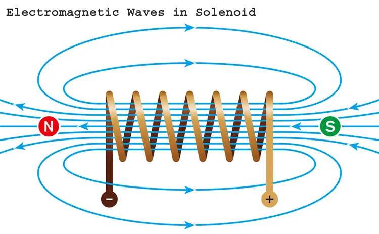
In below fig. when the switch is closed solenoid or electromagnet creates electromagnetic waves (flux) around it and iron strip which has lower reluctance than air gets attracted to solenoid. But after this the circuit gets open and hammer which moves with iron strip will come back to metal contactor which in turn again completes the circuit making solenoid to produce waves and again iron strip gets attracted to solenoid. This action is repeated till the switch is closed state or sometimes when the person inside the house finally meets the person at the door entrance.
Simulink model:
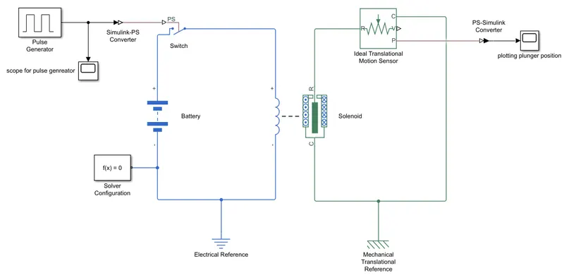
Explaination of Model in steps:
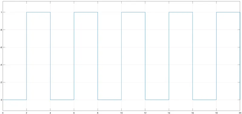
1. Pulse generator block is used as input signal which generates pulse of Amplitude=1, Period=4 secs, Pulse width=50, phase delay=2 secs.
2.Which creates the situation of switch being open closed for 2 secs alternatively.
3.Battery provides the required voltage to solenoid. Voltage rating of batt. is set similar to voltage rating of solenoid which is 50 V here.
4. Solenoid block have a plunger in it which moves as solenoid gets energised and de-enegised acc. to the signal given to it.
5. It is the position of plunger which we are going to plot using scope block. Position of plunger will make us realize whether our model is working as we have desired or not.
6. We will measure position of plunger using Ideal Translational Motion Sensor. This block represents a device that converts an across variable measured between two mechanical translational nodes into a control signal proportional to velocity or position. We can specify the initial position (offset) as a block parameter.
NOTE:
Simulink-PS converter is used to convert any simulink signal to physical signal and PS-simulink converter does the vice-versa.
Solver config. is used to specify simulation options for our physical system, such as the type of solver to use, initialization options, and the sample time for the simulation.
Electrical Reference block represents an electrical ground. Electrical conserving ports of all the blocks that are directly connected to ground must be connected to an Electrical Reference block. A model with electrical elements must contain at least one Electrical Reference block.
Mechanical Translational Reference block represents a reference point, or frame, for all mechanical translational ports. All translational ports that are rigidly clamped to the frame (ground) must be connected to a Mechanical Translational Reference block.
SIMULATION RESULTS:
INPUT SIGNAL:
PLUNGER POSITION PLOT :
1) Plunger mass=0.1 kg and Damping=1 N/(m/s)
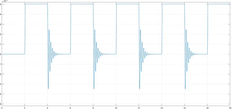
2) When Plunger mass=0.01 kg and Damping=4 N/(m/s)
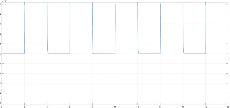
By adujsting plunger mass and damping values we get waveform of very less distortion.
Hence From simulation results it is concluded that plunger is moving according to the signal provided to it with the help of solenoid.
CHALLENGE 2
In this challenge we have to turn fan ON and OFF whenever the temp. of the heater is above 25 deg celsius or 298.15 K.
We will use thermsistor to sense the temp. and a BLDC or a simply DC motor as fan.
Simulink model will give us a more broad idea about the functioning of the model but first we will understabd how some the components work in this model.
1. THERMISTOR:
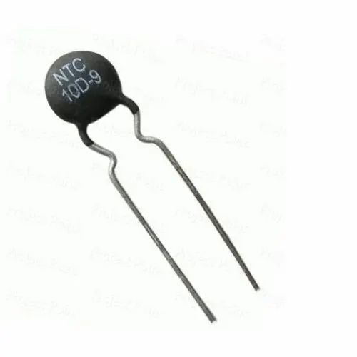
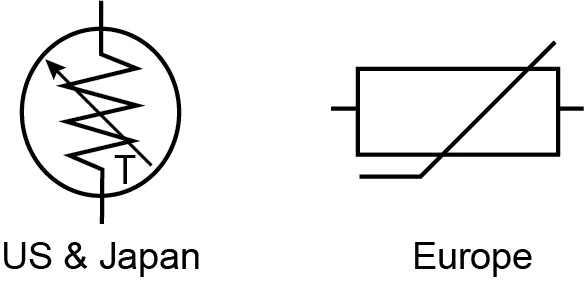
A thermistor is a resistance thermometer, or a resistor whose resistance is dependent on temperature. The term is a combination of “thermal” and “resistor”. It is made of metallic oxides, pressed into a bead, disk, or cylindrical shape and then encapsulated with an impermeable material such as epoxy or glass.
There are two types of thermistors: Negative Temperature Coefficient (NTC) and Positive Temperature Coefficient (PTC). With an NTC thermistor, when the temperature increases, resistance decreases. Conversely, when temperature decreases, resistance increases. This type of thermistor is used the most.
A PTC thermistor works a little differently. When temperature increases, the resistance increases, and when temperature decreases, resistance decreases. This type of thermistor is generally used as a fuse.
Typically, a thermistor achieves high precision within a limited temperature range of about 50ºC around the target temperature. This range is dependent on the base resistance.
How to use thermistor to sense temp. ?
So how can we use a thermistor to measure temperature. Hopefully by now we realise that a thermistor is a resistive device and therefore according to Ohms law, if we pass a current through it, a voltage drop will be produced across it. As a thermistor is an passive type of a sensor, that is, it requires an excitation signal for its operation, any changes in its resistance as a result of changes in temperature can be converted into a voltage change.
The simplest way of doing this is to use the thermistor as part of a potential divider circuit as shown. A constant supply voltage is applied across the resistor and thermistor series circuit with the output voltage measured from across the thermistor.
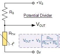
If for example we use a 10kΩ thermistor with a series resistor of 10kΩ, then the output voltage at the base temperature of 25oC will be half the supply voltage as 10Ω/(10Ω+10Ω) = 0.5.
When the resistance of the thermistor changes due to changes in temperature, the fraction of the supply voltage across the thermistor will also change producing an output voltage which is proportional to the fraction of the total series resistance between the output terminals. Thus the potential divider circuit is an example of a simple resistance to voltage converter where the resistance of the thermistor is controlled by temperature with the output voltage produced being proportional to the temperature. So the hotter the thermistor gets, the lower the ouput voltage.
If we reversed the positions of the series resistor, RS and the thermistor, RTH, then the output voltage would change in the opposite direction, that is the hotter the thermistor gets, the higher the output voltage.
FAN: We can use a BLDC motor or a simply DC motor as our fan which gets on whenever the temp is above 298.15 K OR 25 deg C. Construction of Fan is not that necessary to understand as compared to the thermistor circuit.
We will now see how such thing is achieved using a SIMULINK MODEL:
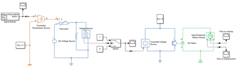
EXPLAINATION/WORKING OF MODEL:
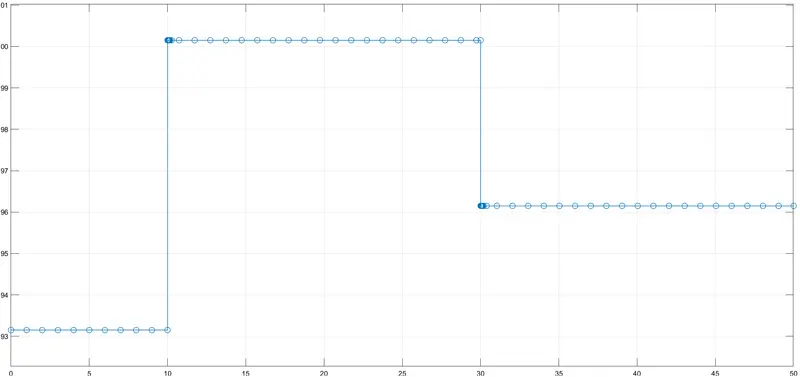
1) A signal builder is used to create the temp vs time signal of following condition: 20 °C(293.15) from 0 to 10 seconds, 27 °C(296.15) from 10 to 30 seconds, 23 °C(300.15) from 30 to 50 seconds.
2) o/p of signal builder is provided to Controlled temp. source. The Controlled Temperature Source block represents an ideal source of thermal energy that is powerful enough to maintain specified temperature difference across the source regardless of the heat flow consumed by the system.
3. Then this signal which is basically a heat energy is sensed by thermistor. Dc voltage source is used to supply voltage across Thermistor and resistor. This circuit represents our potential or voltage divider circuit.
4. As visible from fig. a voltage sensor connected across the resistor and thermistor circuit senses the voltage change according to the change in temp. sensed by thermistor.
5. Function of switch here is to turn the fan on whenever the temp is above 298.15 K. For that we have set threshold value of switch corresponding to 298.15 K which is 0.01199 here.
6. The on signal of switch is taken as input for controlled voltage source. The Controlled Voltage Source block represents an ideal voltage source that is powerful enough to maintain the specified voltage at its output regardless of the current flowing through the source.
7. Which then turns on the DC motor.
8. To track the movement of DC motor we have used ideal rotational motion sensor. Plots are shown in result section below.
SIMULATION RESULTS:
1.INPUT SIGNAL
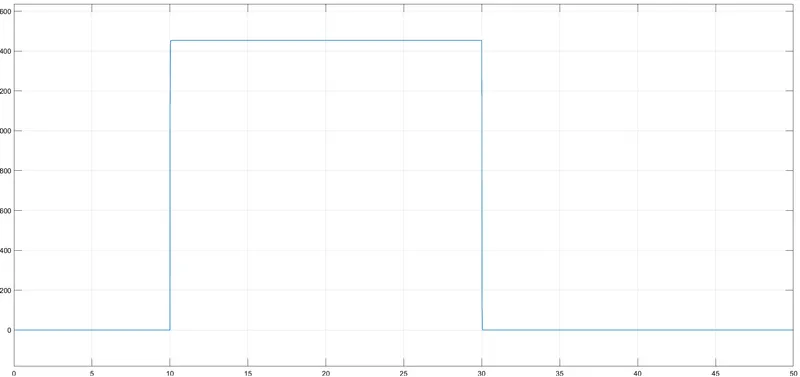
2. PLOT OF SWITCH STATE

3. TIME Vs. ANGULAR VELOCITY
4. TIME Vs ANGULAR DISPLACEMENT
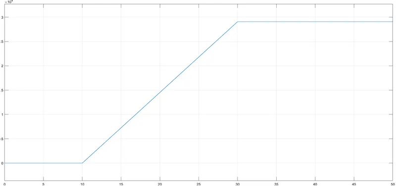
It is evident from the output switch plot that our siwtch got turned on when the temp was above 298.15 K. Because in time span of 10 to 30 secs the signal has a value higher than 298.15 K. We have also plot the motion of the DC motor to make it clear that the model is meeting the required demand.Hence the model is accomplished successfully.