Week-6 Challenge: EV Drivetrain
AIM:
1. Which types of power converter circuits are employed in electric and hybrid electric vehicle?
2. An Electric Vehicle's powertrain with 72V battery pack in shown in the diagram below. The duty ratio for acceleration operation is 'd1' and for the braking operation the duty ratio is 'd2'. What is EV steady state speed if duty cycle is 70%?
3. Refer to the blog on below topic:
Induction Versus DC brushless motors by Wally Rippel, Tesla
Explain in brief about author’s perspective.
OBJECTIVE:
To be able to deal with power electronincs, chopper controlled speed of DC drive and different traction motors in EV.
AIM 1:
Which types of power converter circuits are employed in electric and hybrid electric vehicle?
Power converter are semiconductor devices which either converts power (from AC to DC or Constant DC to pulsating DC) or change the level of the power by making change V or I parameters.
POWER CONVERTERS IN EV:
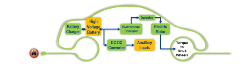
Battery charger: Consists of AC to DC converter also called rectifier
DC-DC converter or chopper: For Aux. loads
Bi-directional converter (To implement regeneration): Which allows power flow in both directions and contains AC-DC, DC-AC and DC-DC (chopper) converter in single unit.
Inverter: Converts DC voltage from battery to AC for motor.
Typical schematic of power conversion flow in EV is shown below.
POWER CONVERTERS IN HEV:
There is no specific diffrence between the converters used in EV and HEV if purpose is taken as a context .
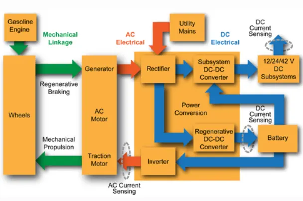
Power conversion flow schematic of HEV shown below gives us the idea about the placement of power conversions devices in the HEV powertrain system.
As you can see instead of bi-directional converter a seperate regenerative DC-DC chopper is used to convert the mechanical energy from gasoline engine to alternator(generator) to store energy.
=============================================================================
AIM 2:
An Electric Vehicle's powertrain with 72V battery pack in shown in the diagram below. The duty ratio for acceleration operation is 'd1' and for the braking operation the duty ratio is 'd2'. What is EV steady state speed if duty cycle is 70%?
Data available:
Batt. pack voltage Vb=72 V,
d1 & d2 are acceleration and braking dutycylce respectively.
Va=72 V
Ia=400 A
Ra=0.5 Ω
kϕ=0.7 volt seconds
Switching frequency=400 Hz
vehicle speed torque char. eqn `tau=24.7+0.0051omega^2` eq (1)
Solution:
Supply voltage to motor terminal @ 70% duty cycle is 0.7*72=50.4 V
Torque speed eq. of DC motor is given as: `(V.kϕ)/(Ra)−(kϕ)^2/(Ra)⋅ω`
putting respective values in above eq. we get
`tau=70.56-0.98omega` eq (2)
Now as we know while designing vehicle we try to match motor speed-torque char to that of vehicle. Using same logic here we match eq 1 and 2.
`70.56-0.98omega` = `24.7+0.0051omega^2`
Rearranging the eq. we get
`0.0051omega^2+0.98omega-45.86=0` eq (3)
eq (3) represents the quadratic eq of form `ax^2+bx+c`
where a=0.0051 b=0.98 c=-45.86 and we can calculate speed intercepts of this eq using quadratic eq solver method:
`omega=(-bpmsqrt(b^2-4ac))/(2a)`
Putting the respective values we get `omega=38.91` rad/s
Steady speed of EV @ 70% duty cycle is 38.91 rad/s.
=============================================================================
AIM 3:
Case study:
Induction Versus DC brushless motors by Wally Rippel, Tesla
Wally rippel has seen the making of EVs for a long time. His prespective here is to throw light on the advancement happening in the production of EVs and stressing that no particular motor can meet our all requirement. He shares his experience of designing and manufacturing of EVs. Lead acid batteries are now replaced by lithium ion batteries, Brushed DC by BLDC or IM, contacters by modulating inverters. It is observed here the advancements happened but at the time he wanted us to realise that there is no major advancements happening after this.
Walley then explains about construction and working of BLDC and IM so that we can get idea about functioning of two motors. Stators of both the motors were similar in construction but stator of BLDC needed pahse inverter and rotor positioning sensor to work. Rotor of BLDC consists of magnets whereas rotor of IM is made of circular stacked steel laminations with conductors inside them which are shorted at the end using ring. As he fiurther explains you will see that IM won when supply was direct from utility. He then says about limitations in IM. IM dont much torque range and they are constant speed drive means no varrting speed. IM seems to lost competition but then walley says with inverter we can convert DC to AC and the frequency of signal can be varied using that inverter. If we add Feedback signal we can also achieve the exact frequency motor desires to run on.
Walley then explains about how can we achieve High torque low speed char. from motor. One way to achieve that was strengthning magnetic field. In BLDC we cant do that as B field is produced by PM. But IM was able to do that as it runs on the principal of induction. But still peak performance of BLDC was high than IM. Magnet in BLDC are costly and PM are difficult to handle when ferromagnetic materials are close to it.
IM seems to be winner but then walley says that IM is very difficult to control. It involves very complex and sophisticated techniques to implement control anology if we are using IM. Damn IM was almost the winner.
Wally concludes that BLDC will rule all HEV and IM will be useful in high applications EV. At least now we must conveyed that wally wanted us to realise that NO MOTOR CAN SERVE ALL PURPOSE.