Week - 4
CHALLENGES:
CHALLENGE 1: Implement control logic of a “washing machine” using Stateflow as per given sequence:
- If the power supply is available, the system gets activated
- If the Water supply is not available, stop the process & indicate through LED
- Soaking time should be 200s followed by Washing time of 100s.
- Then rinsing happens for next 20s & dryer runs for 50s
After all the processes have completed turn on the finished LED
CHALLENGE 2: Make a Simulink chart for the “Gear shift” logic as per below conditions:
Speed Range(kmph) Gear
0 to 15 1
16 to 25 2
26 to 40 3
41 to 60 4
Above 61 5
Give speed input while the simulation is running & display the gear number.
CHALLENGE 1:
In this challenge we have to use stateflow feature of Simulink to implement the control logic of washing machine as per given data. Before that in we need to know two things
What is stateflow in simulink? and What is washing machine?
What is stateflow in simulink?
Stateflow provides a graphical language that includes state transition diagrams, flow charts, state transition tables, and truth tables. You can use Stateflow to describe how MATLAB algorithms and Simulink models react to input signals, events, and time-based conditions.
Stateflow enables you to design and develop supervisory control, task scheduling, fault management, communication protocols, user interfaces, and hybrid systems.
With Stateflow, you model combinatorial and sequential decision logic that can be simulated as a block within a Simulink model or executed as an object in MATLAB. Graphical animation enables you to analyze and debug your logic while it is executing. Edit-time and run-time checks ensure design consistency and completeness before implementation.
What is washing machine?
A washing machine is a machine that washes dirty clothes. It contains a barrel into which the clothes are placed. This barrel is filled with water, and then rotated very quickly to make the water remove dirt from the clothes. Most washing machines are made so that detergent (liquids or powders) can be put into the machine. These can help make the clothes cleaner.
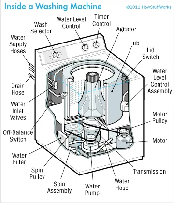
Washing machines have ways to control how the machine operates. Some of the possible controls are temperature of the water, time of the wash cycle (before the soapy dirty water is rinsed out), number of wash cycles before completing.
Types of washing machines
Washing machines may be fully automatic or partly automatic.
Semi-Automatic Washing Machines: Semi-automatic washing machines have separate sections for Dryer and Washer.
Fully-Automatic Washing Machines: Fully-automatic washing machines are easier to use. They have only one section for washing and for spin-drying.
Washing machines may load from the top or the front.
Front loading: A front loading washing machine has a door in the front. The clothes to be washed have to be put in and the door closed before the barrel can fill with water.
Top loading: With a top loading washing machine, the opening is at the top. The barrel can be filled with water and soap before the clothes are put in for washing.
Stacked washer and dryer: Sometimes a washing machine and a clothes dryer are put together. The washing machine is usually on the bottom of the stack because the water in it makes the machine heavier than the dryer.
SIMULINK MODEL/SATEFLOW CHART OF CONTROL LOGIC:
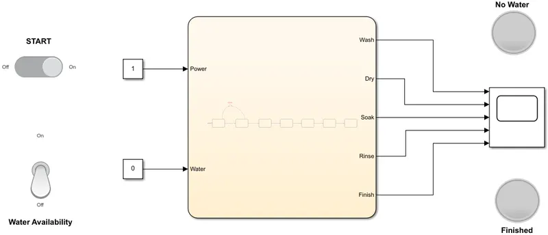
INSIDE CHART/STATEFLOW :
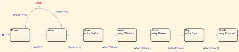
EXPLAINATION OF MODEL :
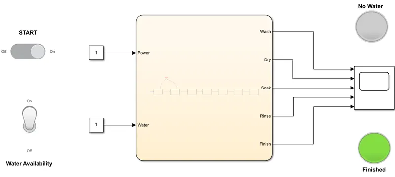
1. Slide switch is used to start the process similarly toggle switch is used to make water supply available as per our wish.
2. Inside chart block: Block like structure are simply states.
3. Power and water state are active when the respective switches on. But either of this two or both states are inactive then signals are send to junction block to stop the process.
Once this two state are active fowllowing operations occur in a given sequence:
a) Soaking for 200s, b) washing for 100s, c) rinsing for 20s, d) drying for 50s.
RUNNING THE MODEL AND CAPTURING EVENT:
EVENT: Unavailability of water indicated by LED labelled "NO WATER"
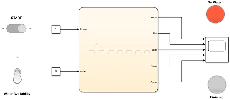
EVENT: Making water available and finished washing indicated by LED labelled "Finished"
PLOTTING ACTIVE TIME OF STATES:
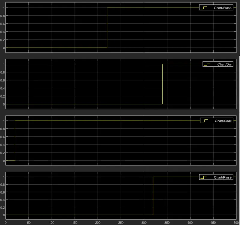
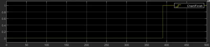
It is yet conclusive from the above events captured that the machine stopped when the water was unavaible and was indicated through red LED and when the washing was done or finished it was indicated by green LED.
_________________________________________________________________________________________
CHALLENGE 2:
In this challenge we have to show the gear shift logic in stateflow diagram. We will first acquire knowledge about gear transmisson systems in vehicle.
What is gear transmission system?
A transmission is a machine in a power transmission system, which provides controlled application of power. Often the term 5-speed transmission refers simply to the gearbox, that uses gears and gear trains to provide speed and torque conversions from a rotating power source to another device.
The most common use is in motor vehicles, where the transmission adapts the output of the internal combustion engine to the drive wheels. Such engines need to operate at a relatively high rotational speed, which is inappropriate for starting, stopping, and slower travel. The transmission reduces the higher engine speed to the slower wheel speed, increasing torque in the process. Transmissions are also used on pedal bicycles, fixed machines, and where different rotational speeds and torques are adapted.
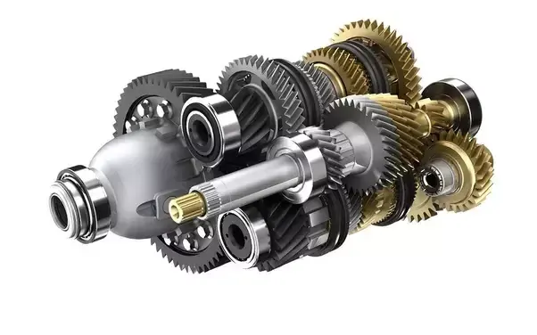
Often, a transmission has multiple gear ratios (or simply "gears") with the ability to switch between them as speed varies. This switching may be done manually (by the operator) or automatically (by a control unit). Directional (forward and reverse) control may also be provided. Single-ratio transmissions also exist, which simply change the speed and torque (and sometimes direction) of motor output.
SIMULINK/STATEFLOW MODEL:
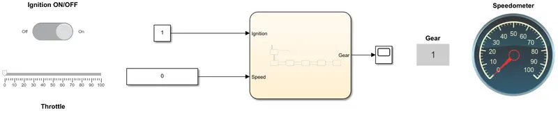
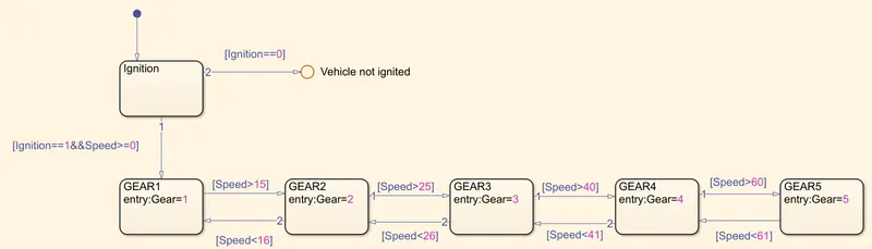
EXPLAINATION OF MODEL:
1. Vehicle is ignited by using slider switch.
2. After the ignition sate is active whole operation depends on Speed paramater.
3. We are increasing or decreasing speed using slider. Using Slider we can also give input while simulation is running.
4. According to the speed parameter the gear shift occurs as given below-
Speed Range(kmph) Gear
0 to 15 1
16 to 25 2
26 to 40 3
41 to 60 4
Above 61 5
RUNNING THE MODEL AND CAPTURING THE EVENT:
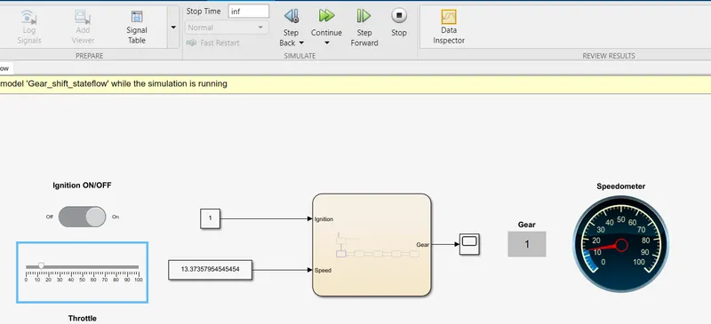
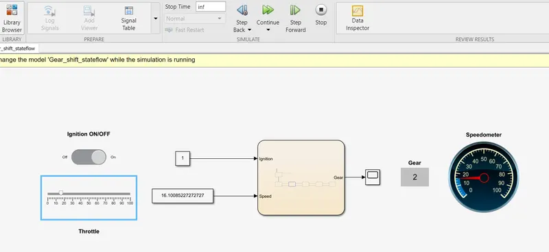
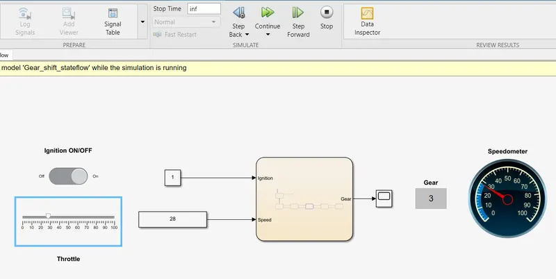
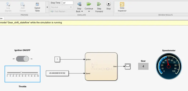
To give INPUT in run time enviornment slider is used and Stop time=inf . Speed is shown using speedometer gear 1 to gear 5 events have been captured and shown below:
GEAR 1
GEAR 2
GEAR 3
GEAR 4
GEAR 5
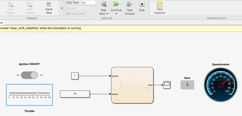
Hence from above events it is evident that our model did run as per the gear shift logic given.