Week 7-Long Piston With Cam
Long Piston with Cam - Simulation Using
ANSYS Workbench 2020 R2
Thejan Sasilal
OBJECTIVES
For this challenge, you will have to perform a transient analysis on a piston and cam mechanism model that has been provided to you. You need to run the analysis with Frictionless contact, Frictional with 0.1 and 0.2 as the frictional contact for a total of 3 cases. Find out the Equivalent Stress, Directional Deformation and Equivalent Elastic Strain and compare them for all the three cases. Give an inference as to why the results vary between cases.
- INTRODUCTION
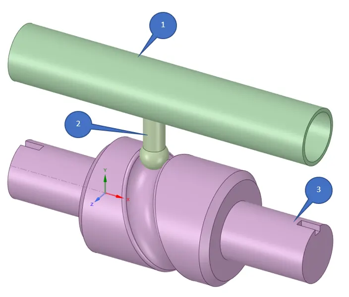
In this challenge, we are simulating the Long Piston with Cam to find out the structural abilities of the system.
Parts:
1- Barrel
2- Cam Follower
3- Barrel Cam
- DESIGN SPECIFICATION
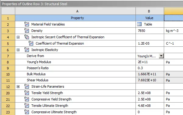
Assigned Structural Steel as the materials for each geometry from engineering data.
- STATIC ANALYSIS
Open Mechanical modeller for analysis.
Consider all units are in metric.
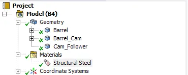
Rename geometry as Barrel, Barrel_Cam & Cam_Follower
Consider Stiffness behavior as Rigid for Barrel & Barrel Cam.
3.1 CONNECTIONS
Contact is said to occur when the surfaces of two separate objects touch each other such that the surfaces are mutually tangent to each other. The surfaces in contact do not interpenetrate and can transmit forces from one body to the other. In order to prevent the interpenetration between the surfaces, the ANSYS program or any FEA software has to establish relations between the surfaces and this is done using CONTACT FORMULATIONS. When penetration is prevented by the program, it is said to have enforced Contact Compatibility. When the program fails to enforce contact compatibility between two surfaces in contact, interpenetration occurs to a large extent and the solver will face convergence issues and be forced to stop. |
In an interface, we define the contact and target. While deciding between these two, we should keep in mind that ANSYS considers the contact body as the one which is not allowed to penetrate into the target body. But the target is allowed to penetrate into the contact body. If you are unsure of the behaviour of your system, then you can choose Symmetric type of contact. Otherwise, an Asymmetric type of contact can be used. |
1. CONTACTS
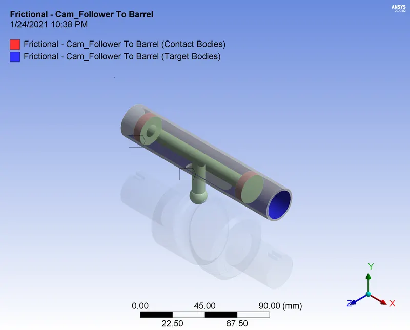
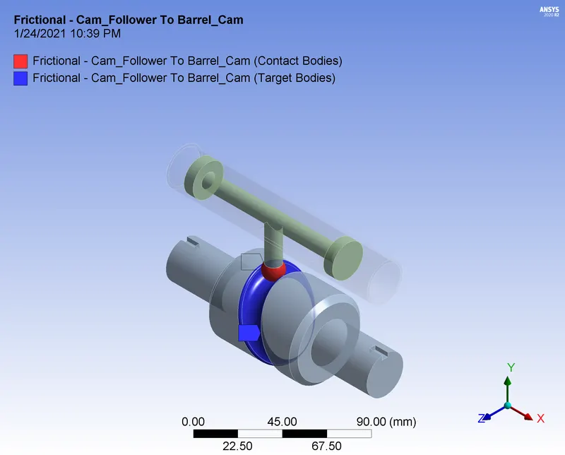
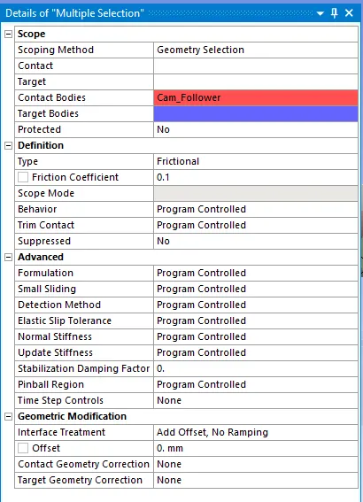
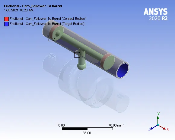
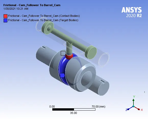
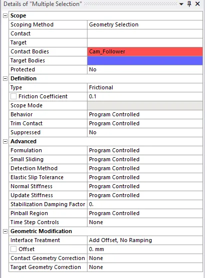
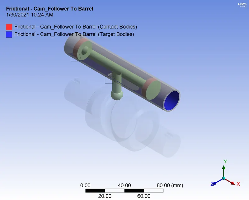
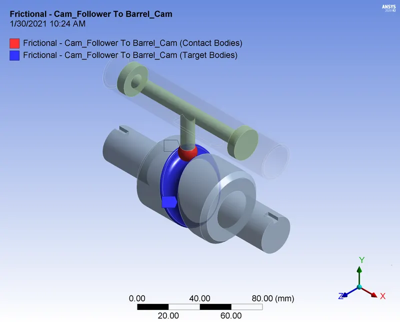
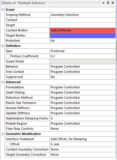
Select the contact & target as shown in the picture. Consider settings as given below.
1.1 - CASE 1 - FRICTIONLESS CONTACT
1.2 - CASE 2 - FRICTIONAL CONTACT
1.3 - CASE 3 - FRICTIONAL CONTACT
JOINTS
Select the contact & target as shown in the picture. Consider settings as given below.
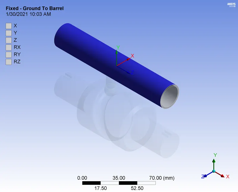
- FIXED – BODY GROUND JOINT FOR BARREL
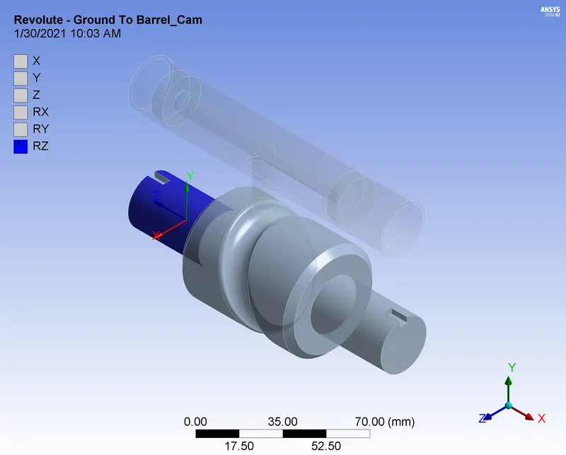
- REVOLUTE – BODY GROUND JOINT FOR BARREL CAM
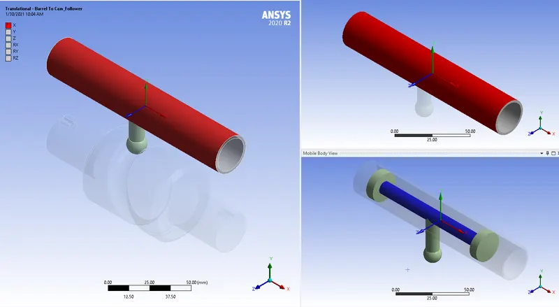
- TRANSLATIONAL– BODY TO BODY JOINT FOR BARREL AND CAM FOLLOWER
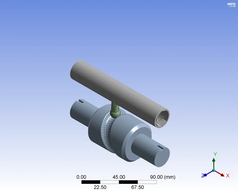
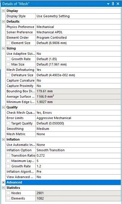
3.2 MESH CREATION
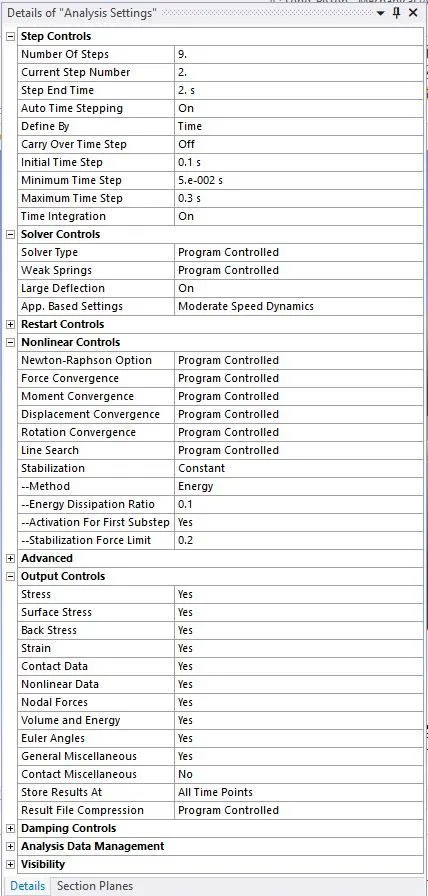
3.3 ANALYSIS SETTINGS
Consider following as the analysis settings for all steps.
3.4 BOUNDARY CONDITION
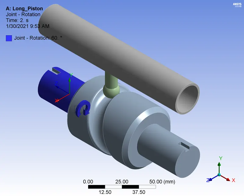
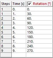
1) Rotational joint for Barrel_Cam. Consider the rotation as given below.
3.5 SOLUTIONS
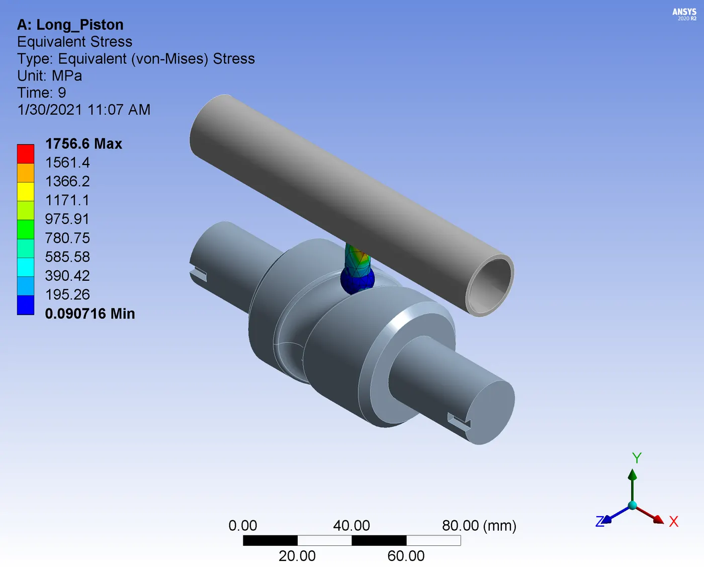
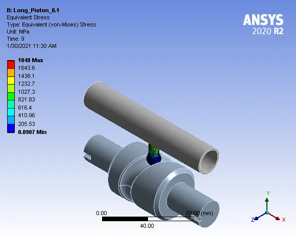
| CASE - 1 (FRICTIONLESS) | CASE - 2 (FRICTIONAL - O.1) | CASE - 3 (FRICTIONAL - 0.2) | COMPARISON |
Equivalent Stress |
|
| 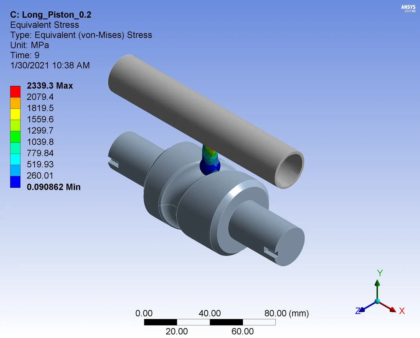 | Stress developing is increasing with increase in friction factor more stress develops at the cam follower stem. |
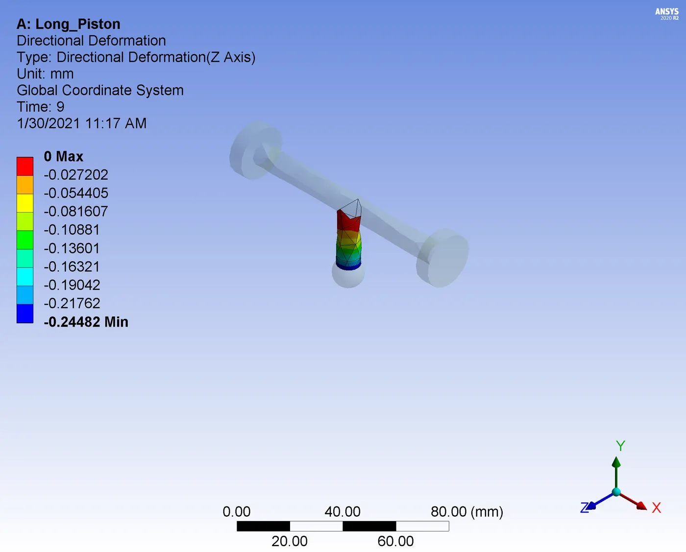
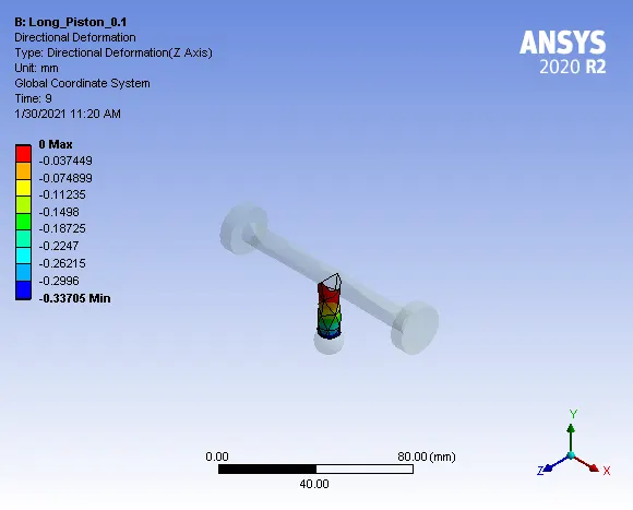
Directional Deformation |
|
|
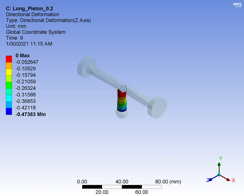
| While checking directional deformation against z axis, it is found that when friction factor increases cam follower stem is deforming more against z axis. |
Equivalent Elastic Strain | 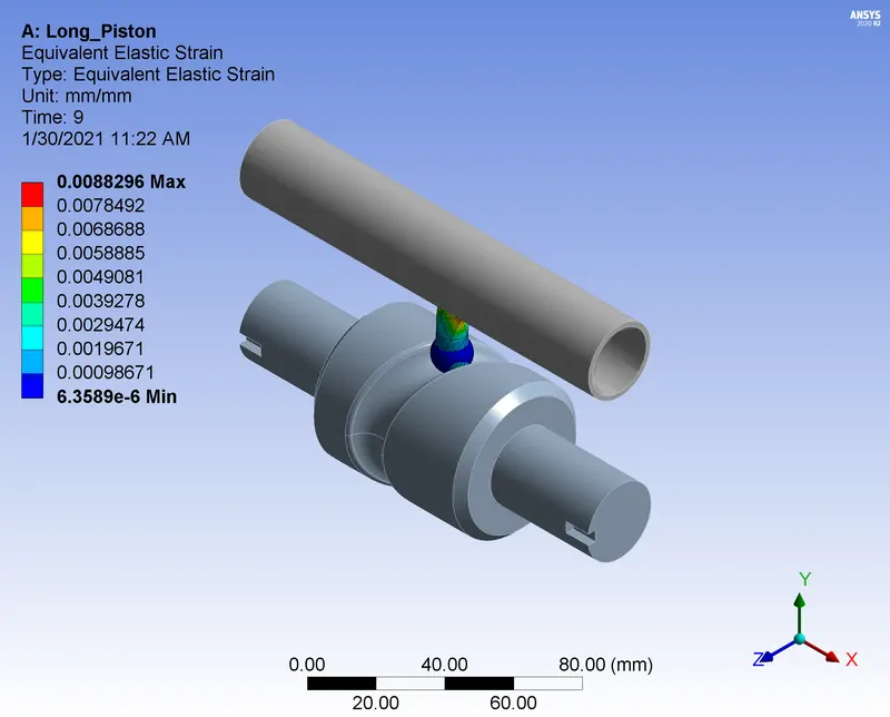 | 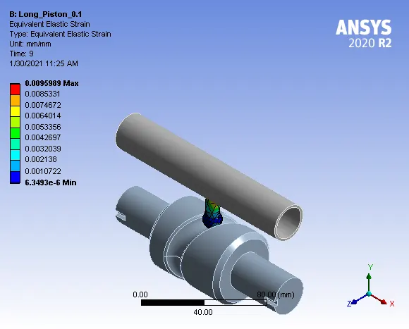 | 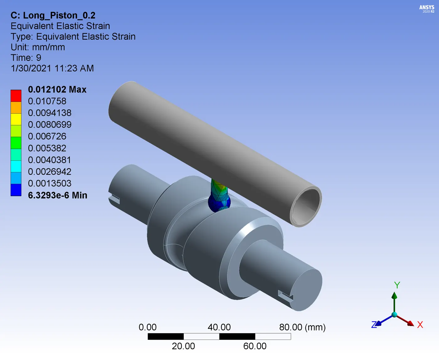 | Strain increasing increases with increase in friction factor. |
- CONCLUSSION
Simulation of Long Piston with Cam conducted with by considering three different cases of frictionless, coefficient of friction 0.1 and coefficient of friction 0.2. From the analysis it is found from all the cases that addition of friction is impacting the stress developed and total deformation. More stress and deformation is developing at the follower stem. For reliable operation of the follower, geometry need to be modified or superior material should be considered for all the cases.