Week 5 Bending of iPhone
Bending of iPhone - Simulation Using
ANSYS Workbench 2020 R2
Thejan Sasilal
OBJECTIVES
For this challenge, simulate the bending of iPhone as per the given cases below
Case 1: Simulate the model as it is given in the video
Case 2: Move the bottom fingers from their defined position to the given position X= 22.5mm & Z= 10mm and obtain the results for the simulation. Also define the S-N curve for the Aluminium Alloy material as per values given below and determine the fatigue life results for the same.
|
Stress, MPa |
Number of Cycles, N |
|
225 |
10000 |
|
175 |
100000 |
|
143 |
1000000 |
|
110 |
10000000 |
|
80 |
100000000 |
Results and Deliverables
Obtain the directional deformation for the model
Factor of Aluminium Alloy NL
Life of the Aluminium alloy for the case
Compare the results and present with the conclusion.
- INTRODUCTION
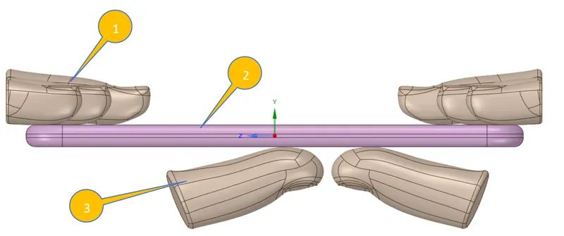
In this challenge, we are simulating the bending process of iPhone with human fingers at different locations to find out the structural abilities of the aluminium frame.
Parts:
1- Fixed fingers
2- iPhone
3- Push Fingers
- DESIGN SPECIFICATION
Assigned the following materials for each geometry from engineering data.
Material Assignment:
1- Fingers: Structural Steel
2- Frame: Aluminium Alloy NL
3- Display: Glass
4- Internals: Polyethylene
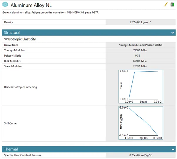
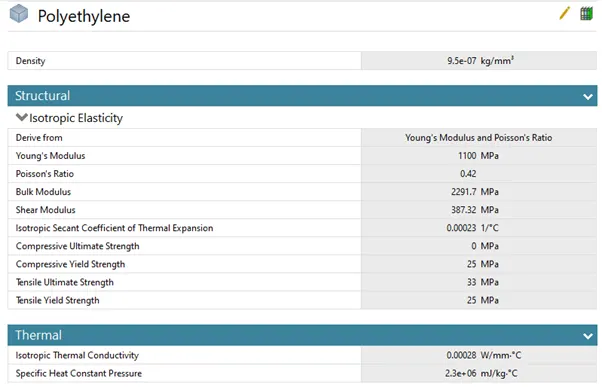
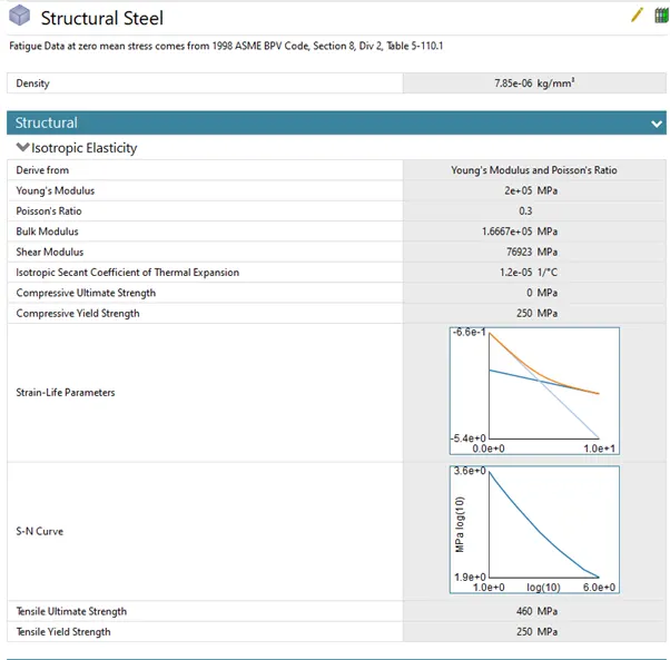
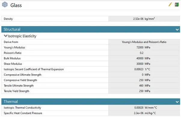
Imported the geometry and open it in Space Claim and check.
- STATIC ANALYSIS
Open Mechanical modeller for analysis.
Consider all units are in metric.
Rename geometry as Display, Frame, Inside, Push Fingers & Fingers
Select Stiffness Behaviour as Flexible for Display, Frame, Inside & Push Finger_Left
Select Stiffness Behaviour as Rigid for Push Finger_Right & other all fingers
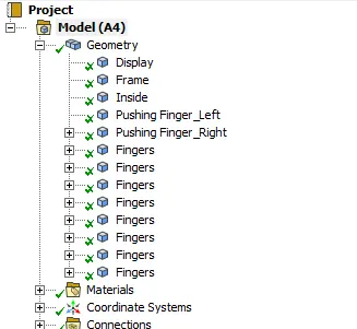
3.1 CONNECTIONS
|
Contact is said to occur when the surfaces of two separate objects touch each other such that the surfaces are mutually tangent to each other. The surfaces in contact do not interpenetrate and can transmit forces from one body to the other. In order to prevent the interpenetration between the surfaces, the ANSYS program or any FEA software has to establish relations between the surfaces and this is done using CONTACT FORMULATIONS. When penetration is prevented by the program, it is said to have enforced Contact Compatibility. When the program fails to enforce contact compatibility between two surfaces in contact, interpenetration occurs to a large extent and the solver will face convergence issues and be forced to stop. |
|
In an interface, we define the contact and target. While deciding between these two, we should keep in mind that ANSYS considers the contact body as the one which is not allowed to penetrate into the target body. But the target is allowed to penetrate into the contact body. If you are unsure of the behaviour of your system, then you can choose Symmetric type of contact. Otherwise, an Asymmetric type of contact can be used. |
1. Consider default contacts and targets except finger to finger contact.
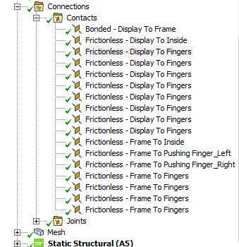
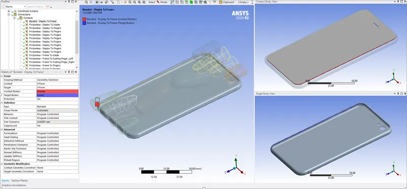
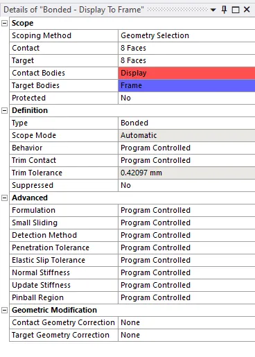
2. Consider the following settings for Display to Frame contact.
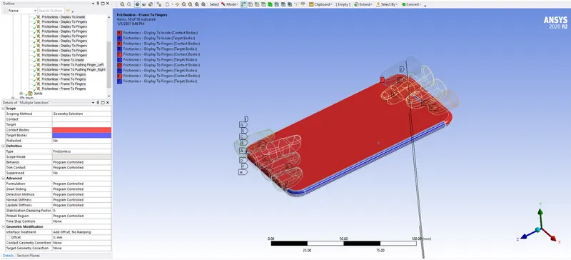
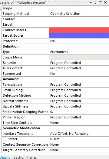
3. Consider the following settings for all other contacts
|
Frictionless: In this type of contact, separation and sliding are both allowed. The coefficient of friction is taken as zero in this case. The user should check the model if it is properly constrained whenever this contact model is used. Weak springs are often added for easier convergence with this model. Bonded: As the name suggests, it allows the user to define a contacting surface like a glued surface. This type of contact does not allow any sliding or separation to take place. |
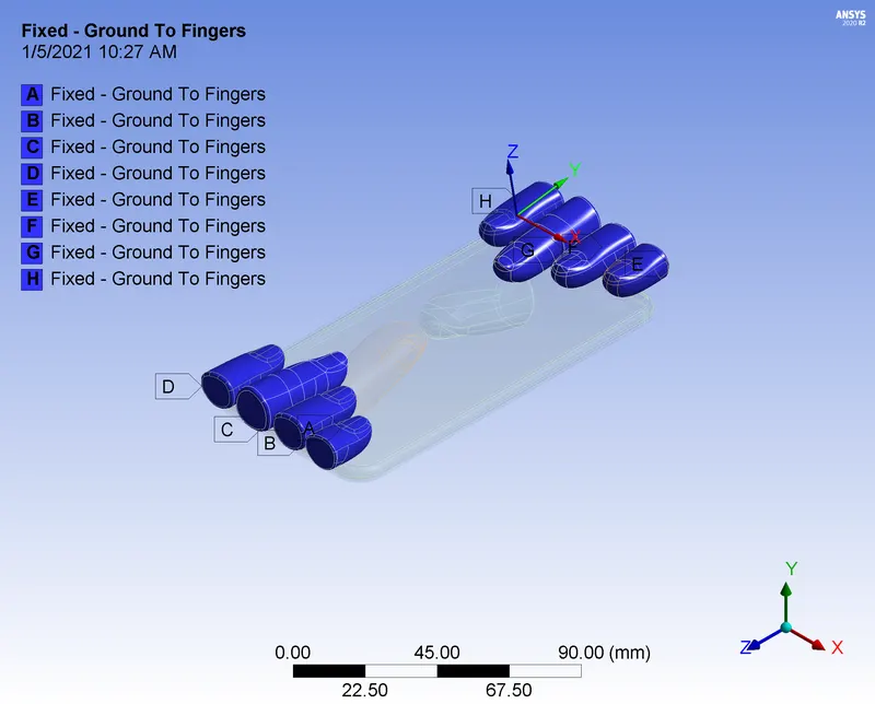
4. Insert Fixed (Body Ground) joint for fixed fingers
5. Insert Translational joint for push fingers
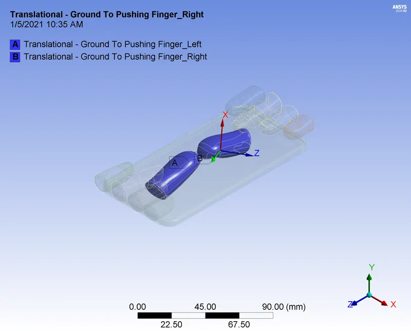
3.2 MESH CREATION
1) Insert Sizing for the selected faces with element size 4 mm.
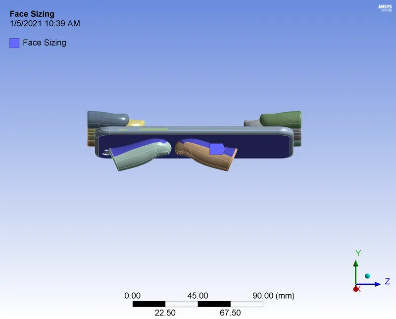
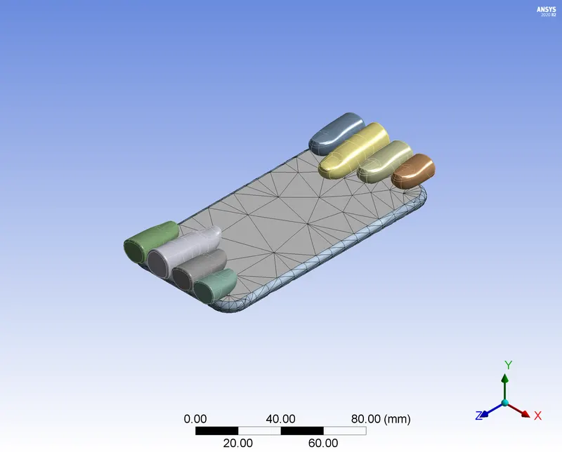
2) Generate Mesh using the following settings
|
Object Name |
Mesh |
|
State |
Solved |
|
Display |
|
|
Display Style |
Use Geometry Setting |
|
Defaults |
|
|
Physics Preference |
Mechanical |
|
Element Order |
Program Controlled |
|
Element Size |
Default |
|
Sizing |
|
|
Use Adaptive Sizing |
Yes |
|
Resolution |
0 |
|
Mesh Defeaturing |
Yes |
|
Defeature Size |
Default |
|
Transition |
Fast |
|
Span Angle Center |
Coarse |
|
Initial Size Seed |
Assembly |
|
Bounding Box Diagonal |
168.39 mm |
|
Average Surface Area |
144.03 mm² |
|
Minimum Edge Length |
8.5254e-002 mm |
|
Quality |
|
|
Check Mesh Quality |
Yes, Errors |
|
Error Limits |
Standard Mechanical |
|
Target Quality |
Default (0.050000) |
|
Smoothing |
Low |
|
Mesh Metric |
None |
|
Inflation |
|
|
Use Automatic Inflation |
None |
|
Inflation Option |
Smooth Transition |
|
Transition Ratio |
0.272 |
|
Maximum Layers |
5 |
|
Growth Rate |
1.2 |
|
Inflation Algorithm |
Pre |
|
View Advanced Options |
No |
|
Advanced |
|
|
Number of CPUs for Parallel Part Meshing |
Program Controlled |
|
Straight Sided Elements |
No |
|
Rigid Body Behavior |
Dimensionally Reduced |
|
Rigid Face Mesh Type |
Quad/Tri |
|
Triangle Surface Mesher |
Program Controlled |
|
Topology Checking |
Yes |
|
Pinch Tolerance |
Please Define |
|
Generate Pinch on Refresh |
No |
|
Statistics |
|
|
Nodes |
12919 |
|
Elements |
5569 |
3.3 ANALYSIS SETTINGS
Consider following as the analysis settings for all steps.
|
Object Name |
Analysis Settings |
|
State |
Fully Defined |
|
Step Controls |
|
|
Number Of Steps |
8. |
|
Current Step Number |
1. |
|
Step End Time |
1. s |
|
Auto Time Stepping |
Program Controlled |
|
Solver Controls |
|
|
Solver Type |
Direct |
|
Weak Springs |
Program Controlled |
|
Solver Pivot Checking |
Program Controlled |
|
Large Deflection |
On |
|
Inertia Relief |
Off |
|
Quasi-Static Solution |
Off |
|
Rotordynamics Controls |
|
|
Coriolis Effect |
Off |
|
Restart Controls |
|
|
Generate Restart Points |
Program Controlled |
|
Retain Files After Full Solve |
No |
|
Combine Restart Files |
Program Controlled |
|
Nonlinear Controls |
|
|
Newton-Raphson Option |
Program Controlled |
|
Force Convergence |
Program Controlled |
|
Moment Convergence |
Program Controlled |
|
Displacement Convergence |
Program Controlled |
|
Rotation Convergence |
Program Controlled |
|
Line Search |
Program Controlled |
|
Stabilization |
Constant |
|
--Method |
Energy |
|
--Energy Dissipation Ratio |
0.1 |
|
--Activation For First Substep |
Yes |
|
--Stabilization Force Limit |
0.2 |
|
Advanced |
|
|
Inverse Option |
No |
|
Contact Split (DMP) |
Off |
|
Output Controls |
|
|
Stress |
Yes |
|
Surface Stress |
Yes |
|
Back Stress |
Yes |
|
Strain |
Yes |
|
Contact Data |
Yes |
|
Nonlinear Data |
Yes |
|
Nodal Forces |
Yes |
|
Volume and Energy |
Yes |
|
Euler Angles |
Yes |
|
General Miscellaneous |
Yes |
|
Contact Miscellaneous |
Yes |
|
Store Results At |
All Time Points |
|
Result File Compression |
Program Controlled |
|
Analysis Data Management |
|
|
Solver Files Directory |
D:\7. Skill Lync\6. Week 5\2. Bending of iPhone\Week 5 Bending of iPhone_files\dp0\SYS\MECH\ |
|
Future Analysis |
None |
|
Scratch Solver Files Directory |
|
|
Save MAPDL db |
No |
|
Contact Summary |
Program Controlled |
|
Delete Unneeded Files |
Yes |
|
Nonlinear Solution |
Yes |
|
Solver Units |
Active System |
|
Solver Unit System |
nmm |
|
Large deflection This option helps the solver whether the large deflection, large stain, large rotation happening in the simulation should be taken into account. It is available for static structural and transient structural analysis. Enabling this by ON will help the solver to consider the large strain happening, such as metal forming in a simulation and deflection.
SOLVER CONTROLS Solver controls provide some properties based on the analysis type. For both the static structural analysis and transient structural analysis the common properties are ● Solver type ● Weak springs ● Large deflection Solver type Helps in choosing the required solver type for carrying out a simulation. It offers three options, Program controlled: default option. The program automatically chooses the solver based on the model application. Direct: This is one of the solver types where the solver uses a Sparse solver (solver handles a system of equations where the coefficient matrix entries contain mostly zero) to solve the model. |
3.4 BOUNDARY CONDITIONS
1) Insert Fixed support for Inside
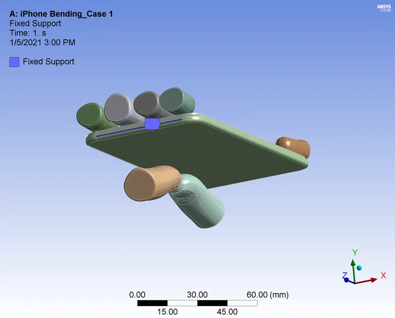
2) Insert Displacement joint for Frame
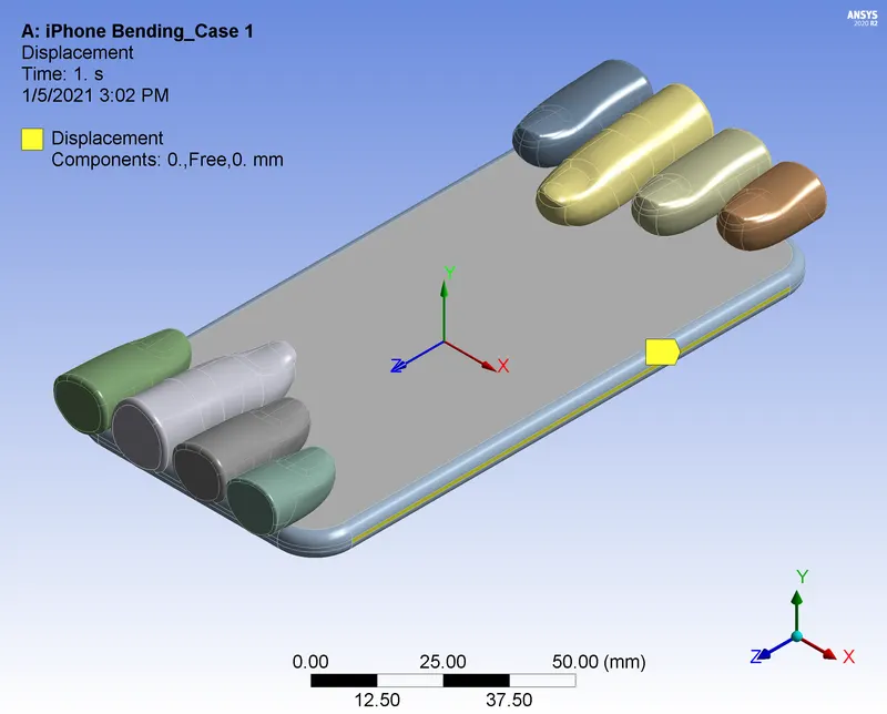
3) Insert Joint Load for Push Fingers individually and input displacement values in X direction
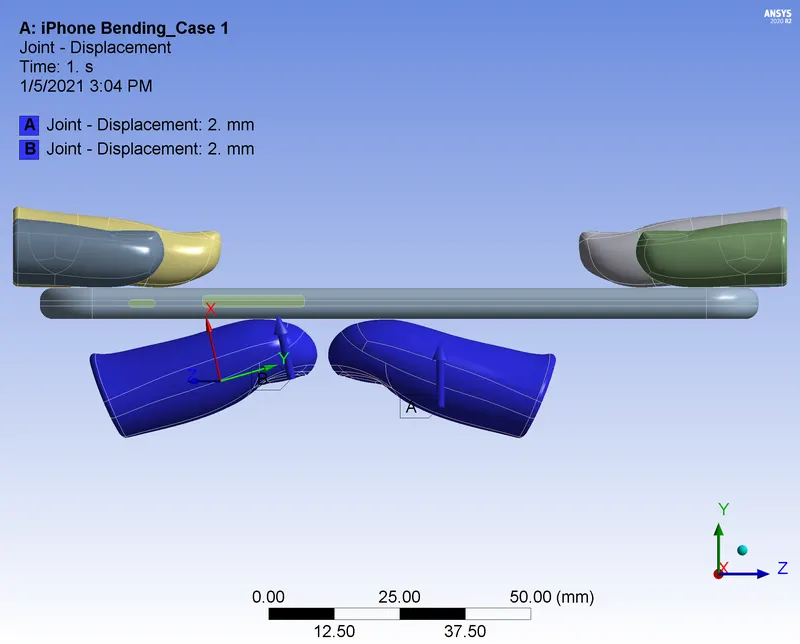
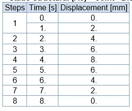
3.5 SOLUTIONS
|
|
CASE - 1 |
CASE - 2 |
COMPARISON |
|
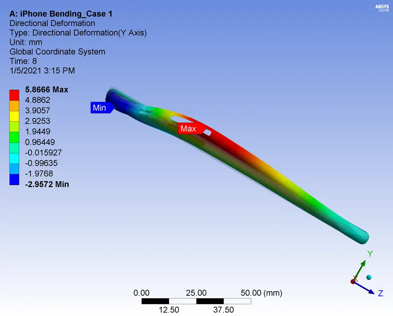
Directional Deformation about Y- axis on Frame |
 |
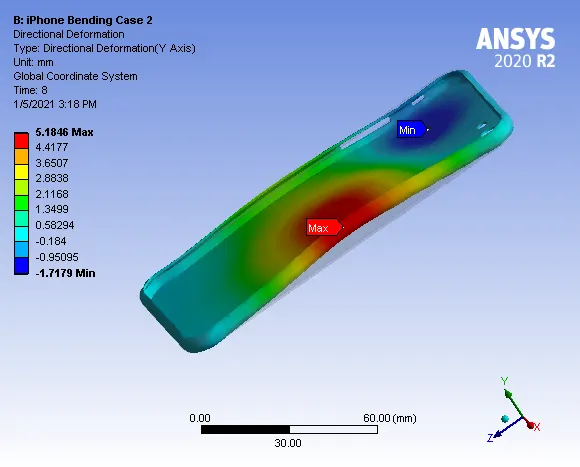 |
Since the application of loading is at geometrically weaker area more deformation occurs in case-1 |
|
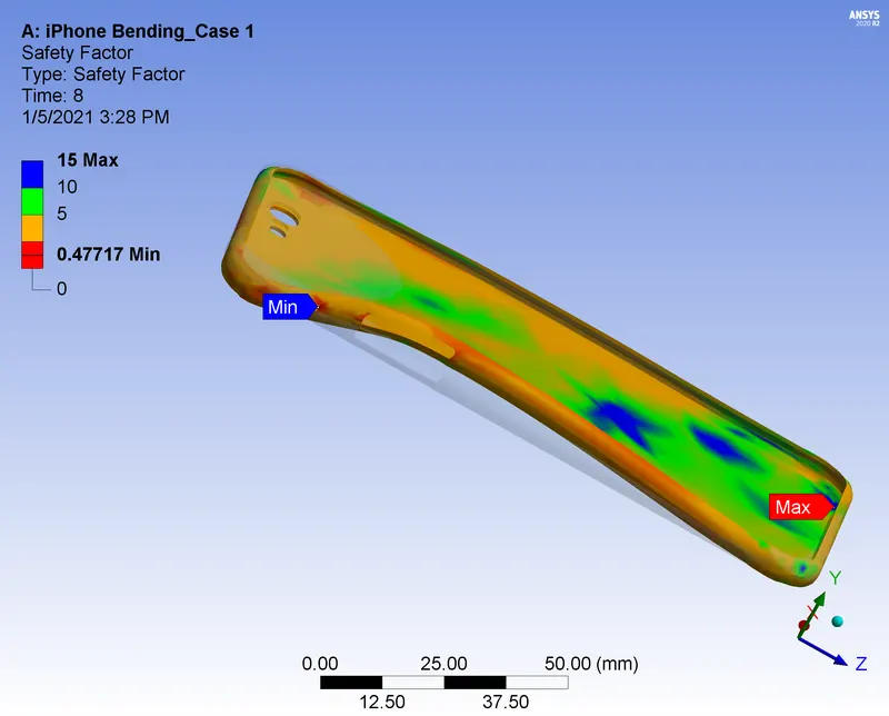
Factor of Safety - Frame |
 |
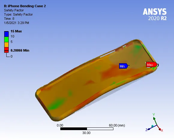 |
In case-1, application loading is at edge of the frmae, stress concentrates on deformed areas only. In case-2, application of loading is at the near to the geometrical center, stress distributes to almost all the area of the frame. Both the cases indicating plastic deformation of the Frame. |
|
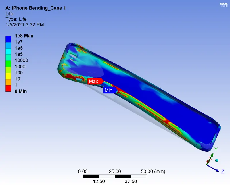
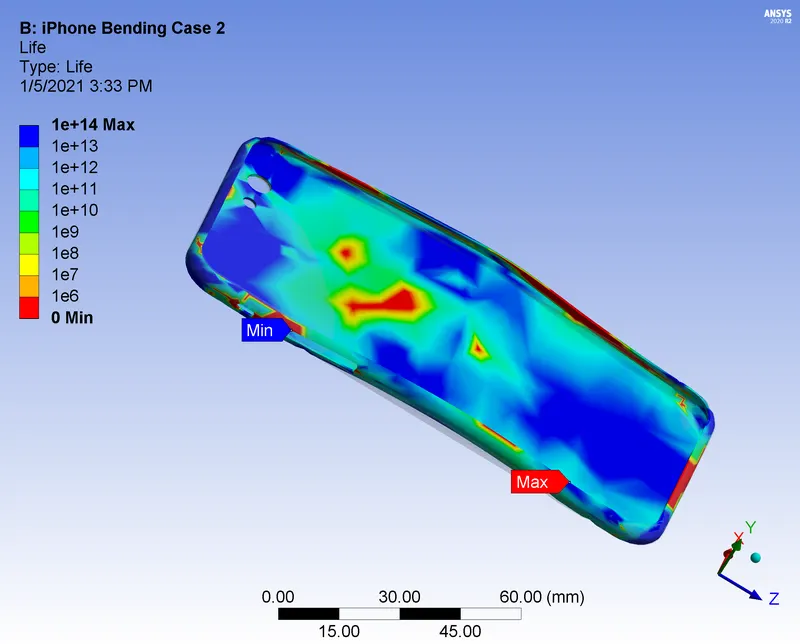
Life Cycle of Frame |
|
|
Both the cases indicating poor life cycle. As it is a plastic deformation in the fist loading cycle itself the frame deforms. |
4. CONCLUSSION
Simulation of bending process of iPhone carried out using Ansys workbench. From the analysis, it is found that the application of the 8mm displacement load at different loacations produces plastic deformation in the Aluminium Alloy Frame. As the point of load application is at different loactions, effect of the deformation is different in both cases. The Aluminium Alloy frame is not able to withstand the 8mm bending load.