Week 2 Railwheel and Track
Static structural analysis on the Rail wheel and Track Setup Using
ANSYS Workbench 2020 R2
Thejan Sasilal
|
Abstract: A rail wheel is a type of wheel specially designed for use on railway tracks. A rolling component is typically pushed onto an axle and mounted directly on a railway carriage. Wheels are cast or forged and are heat-treated to have a specific hardness. New wheels are trued, using a lathe, to a specific profile before being pressed onto an axle. All wheel profiles must be regularly checked to ensure proper interaction between the wheel and the rail. Incorrectly trued, or worn out wheels can increase rolling resistance, reduce energy efficiency and may even cause a derailment. A rail wheel typically consists of two main parts: the wheel itself, and axle. |
OBJECTIVES
Case 1: Multiply the bearing load by 5 times and compare the results with the load of 100000 N (As done in week 2 video). Compare the Total Deformation, Equivalent stress and the life under both the loads
Case 2: Implement a User defined result and calculate the Total Deformation from this result and check if it is the same as that obtained by the inbuilt result by ANSYS for a load of 100000 N.
- DESIGN SPECIFICATION
Selected Structural steel and material of construction from Engineering data.
|
Material Properties of Structural Steel |
||
|
Property |
Value |
Unit |
|
Density |
7850 |
Kg/m3 |
|
Coefficient of Thermal Expansion |
1.2E-05 |
C-1 |
|
Young’s Modulus |
2E+11 |
Pa |
|
Poisson’s Ratio |
0.3 |
|
|
Bulk Modulus |
1.6667E+11 |
Pa |
|
Shear Modulus |
7.6923E+10 |
Pa |
|
Tensile Yield Strength |
2.5E+8 |
Pa |
|
Compressive Yield Strength |
2.5E+8 |
Pa |
|
Ultimate Tensile Strength |
4.6E+8 |
Pa |
- CONNECTIONS
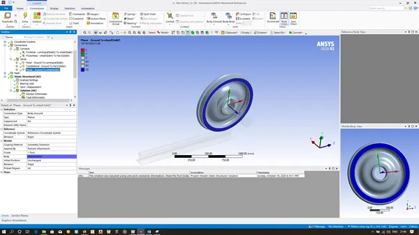
2.1 CONTACTS STTING
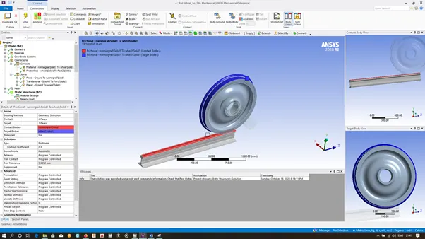
2.1.1 For Wheel & Track Contact
Select wheel outer face, fillet & track top face as geometry
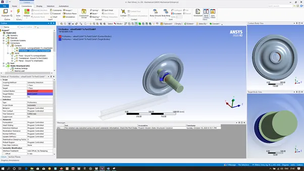
2.1.2 For Wheel & Axle Contact
Select inner face of wheel & outer face of the axle as geometry
2.2 JOINTS
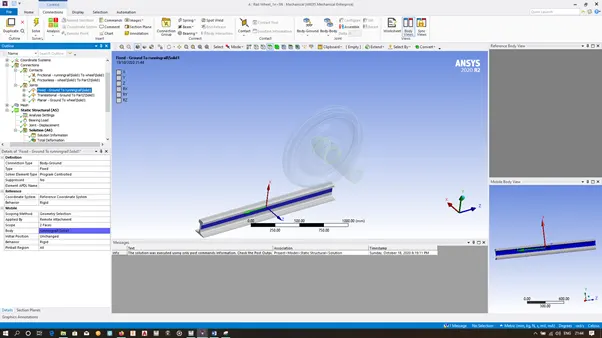
2.2.1 Fixed to ground joint for track
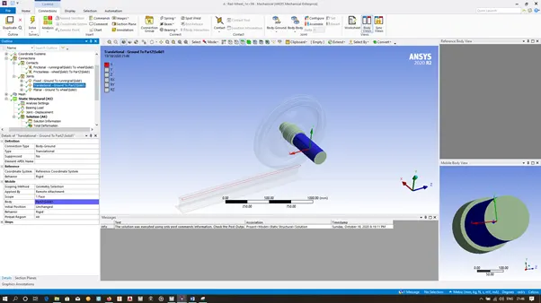
2.2.2 Translational joint for axle
2.2.3 Planar joint for axle
- MESH
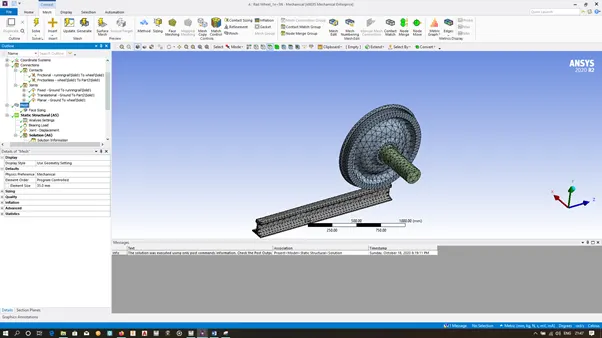
3.1 Global Mesh
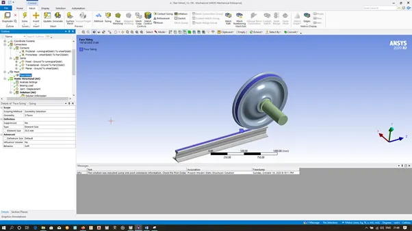
3.2 Face Mesh
- ANALYSIS
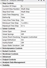
5.1.1 Analysis Settings for first Step
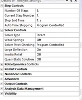
5.1.2 Analysis Settings for step 2 to 5
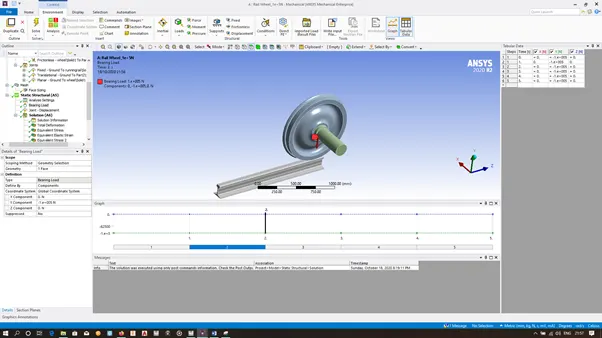
5.2 Bearing Load
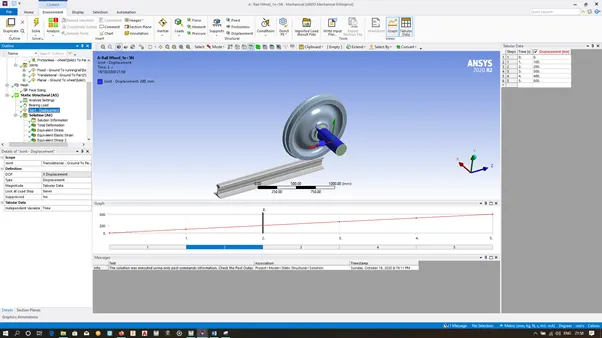
5.3 Joint Load
- SOLUTIONS
CASE 1
|
Bearing Load |
Condition -1 (100000 N) |
Condition -2 500000 N |
Comparison of Both Cases |
|
Total Deformation |
 |
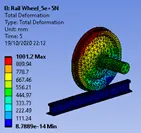 |
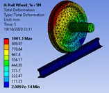
Maximum value of total deformation is almost same in both conditions. Minimum value of total deformation is higher in condition 2 compared to 1. It defines that further deformation due to increment in load is being approaching towards less deformed regions. |
|
Equivalent stress |
 |
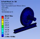 |
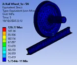
Ultimate Tensile Strength & Yeild Strength of structural steel is 450 MPa & 250 MPa respectively. In condition 1 – maximum stress is less than yeild strength and FOS of 2 is available. In condition 2 FOS os 0.5 is only available. It is evident that in condition 2 failure chance is very high. |
|
Life |
 |
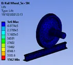 |
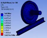
Maximum life cycle is same in both cases. Minimum life cycle is very less in case 2 compared to case 1. |
CASE 2
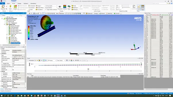
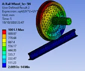
Applying the expression of sqrt(UX^2+UY^2+UZ^2) in the expressions field gives the magntude of total deformation.
|
|
User defined result |
Inbuilt result by ANSYS |
|
|
Total Deformation |
 |
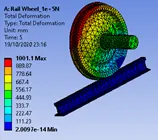 |
The results obtained from user defined result & inbuilt ANSYS result is exactly same. |
- CONCLUSSION
CASE 1
From the analysis of the rail wheel track system with two different loads, it is found the effects of the Total Deformation, Equivalent stress and the life cycle. While comparing both the results, it is evident that the application of 500000N of load is not recommended, as the stress developed is higher than the ultimate tensile strength of the material.
CASE 2
In ANSYS workbench it is possible to solve user defined expressions. The total deformation generated with inbuilt ANSYS workbench & user defined result are exactly same.