Week 3 Sheet metal Bending challenge
Sheet Bending Simulation Using
ANSYS Workbench 2020 R2
Thejan Sasilal
|
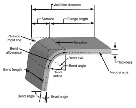
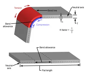
Abstract: Sheet bending is a metal forming process in which a force is applied to a piece of sheet metal, causing it to bend at an angle and form the desired shape. A bending operation causes deformation along one axis, but a sequence of several different operations can be performed to create a complex part. Bent parts can be quite small, such as a bracket, or up to 20 feet in length, such as a large enclosure or chassis. A bend can be characterized by several different parameters. The act of bending results in both tension and compression in the sheet metal. The outside portion of the sheet will undergo tension and stretch to a greater length, while the inside portion experiences compression and shortens. The neutral axis is the boundary line inside the sheet metal, along which no tension or compression forces are present. As a result, the length of this axis remains constant. The changes in length to the outside and inside surfaces can be related to the original flat length by two parameters, the bend allowance and bend deduction. Design Considerations 1. Bend location - A bend should be located where enough material is present, and preferably with straight edges, for the sheet to be secured without slipping. The width of this flange should be equal to at least 4 times the sheet thickness plus the bend radius. 2. Bend radius · Use a single bend radius for all bends to eliminate additional tooling or setups · Inside bend radius should equal at least the sheet thickness 3. Bend direction - Bending hard metals parallel to the rolling direction of the sheet may lead to fracture. Bending perpendicular to the rolling direction is recommended. 4. Any features, such as holes or slots, located too close to a bend may be distorted. The distance of such features from the bend should be equal to at least 3 times the sheet thickness plus the bending radius. 5. In the case of manual bending, if the design allows, a slot can be cut along the bend line to reduce the manual force required. |
OBJECTIVES
Sheet metal bending is to be performed for 3 different materials mentioned below. Variation of certain settings is also to be performed and your conclusions are to be added to the report
Note: Please read the instructions carefully
Run the analysis for the material:
Case 1: Aluminium Alloy 1199(mentioned in the course video), Copper Alloy NL and Magnesium Alloy NL. Find out the Equivalent stress, Equivalent elastic strain and Total Deformation in Y direction and compare the results for the three materials.
Case 2: With the material as Aluminium Alloy, change the friction coefficient to 0.19 and run the analysis as mentioned in Case 1. Compare the results with that in case 1.
Case 3: Refine the mesh on the plate such that it doesn't cross the academic limit. With Aluminium alloy as material, run the analysis as in Case 1 and compare the results.
Submit the challenge as you would do in a proper project report with all relevant details such as settings, mesh size, images and tables included to provide your findings. Also, give an explanation as to which property/ properties of the materials affect the outcome
- INTRODUCTION
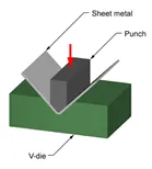
The most common method using in sheet bending is known as V-bending, in which the punch and die are "V" shaped. The punch pushes the sheet into the "V" shaped groove in the V-die, causing it to bend.
In this challenge, we are considering 3 different materials for sheet and comparing results in different conditions.
- DESIGN SPECIFICATION
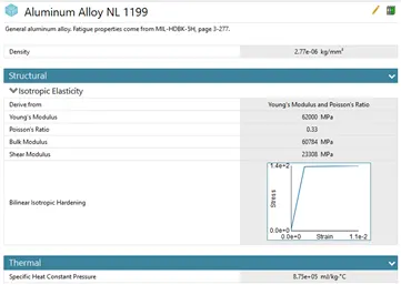
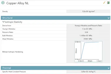
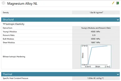
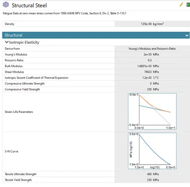
Assigned the following materials for each geometry from engineering data.
Size of the Sheet (L X W X T): 40 X 10 X 1 mm
Material Assignment:
Sheet: Aluminium Alloy 1199 / Copper Alloy NL / Magnesium Alloy NL
Die & Punch: Structural Steel
Imported the geometry and open it in Space Claim and check.
- STATIC ANALYSIS
Open Mechanical modeller for analysis.
Consider all units are in metric.
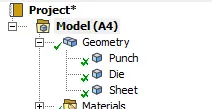
Rename geometry as Punch, Die & Sheet
4.1 CONNECTIONS
|
Contact is said to occur when the surfaces of two separate objects touch each other such that the surfaces are mutually tangent to each other. The surfaces in contact do not interpenetrate and can transmit forces from one body to the other. In order to prevent the interpenetration between the surfaces, the ANSYS program or any FEA software has to establish relations between the surfaces and this is done using CONTACT FORMULATIONS. When penetration is prevented by the program, it is said to have enforced Contact Compatibility. When the program fails to enforce contact compatibility between two surfaces in contact, interpenetration occurs to a large extent and the solver will face convergence issues and be forced to stop. |
Delete all the default contacts generated by Ansys.
|
In an interface, we define the contact and target. While deciding between these two, we should keep in mind that ANSYS considers the contact body as the one which is not allowed to penetrate into the target body. But the target is allowed to penetrate into the contact body. If you are unsure of the behaviour of your system, then you can choose Symmetric type of contact. Otherwise, an Asymmetric type of contact can be used. |
- Insert Manual Contact Region and select following as Contact & Target
- Contact: 3 faces of punch which is directed towards the sheet
- Target: Top face of sheet
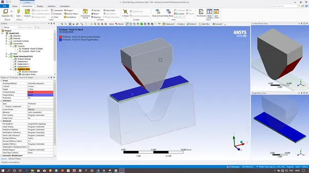
- Insert Manual Contact Region and select following as Contact & Target
- Contact: Bottom face of sheet
- Target: Top faces of Die (7nos)
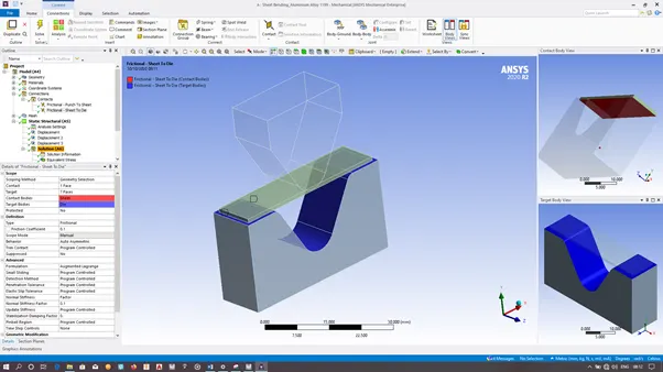
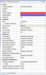
Select both contacts & consider the following settings
|
Frictional: We can specify any non-negative value as the frictional coefficient. So, the contact will handle shear stresses up to what is specified by the frictional coefficient. After this value, sliding will start to take place. Auto Asymmetric: In this type of behaviour, ANSYS chooses the contacts and targets. Essentially, ANSYS automatically tries to create an Asymmetric behaviour between the contacts but you are free to edit the contacts and targets. Augmented Lagrange: This method is also a penalty-based method. It uses the same equation for solving but has an extra augmentation constant, λ. Because there is an extra term in the equation, the contact force becomes less sensitive to the stiffness. So, there will be lesser penetration at the contacts. Hence, this formulation is preferred more. 𝑭𝒏𝒐𝒓𝒎𝒂𝒍= 𝒌𝒏𝒐𝒓𝒎𝒂𝒍× 𝒙𝒑𝒆𝒏𝒆𝒕𝒓𝒂𝒕𝒊𝒐𝒏+ 𝝀 If penetration present is large, the solver will require additional iterations to converge. Contact penetration is allowed in this formulation but it is more controlled than it was in pure penalty method. This method can be used with any type of contact NORMAL STIFFNESS Normal stiffness helps in controlling the amount of penetration between the contact and target surfaces. Normal stiffness value/factor directly helps in the convergence of the solution. If the stiffness value is small, there would be a large amount of penetration, although it is helpful in converging. If the value is large, there won’t be any penetration of the surfaces, but it results in convergence issues. Hence, it is important that a nominal value should be chosen. It provides some options. They are, Program controlled: This is a default setting. The program takes the normal stiffness value/factor. Factor: The normal ‘normal stiffness factor’ range is from 0.01-10. The reasonable value for bonded contacts is chosen as 10, and for other contact types, it is chosen as 1.0 for bulk deformation. If there is a bending deformation, a value of 0.1 can be chosen, but we must be careful that the smaller values of deformation can cause penetration. Value: Here, the stiffness value is provided manually by the user. The value mentioned should be a non-zero positive value. INTERFACE TREATMENT The interface treatment option helps us to define how the contact surface should be treated. It is enabled only when the contact type is set to frictionless, rough, or frictional. Add offset, Ramped effects: Offset is nothing but adding an extra user-inputted distance. Adding offset helps in bringing the two bodies into initial contact with the loading values ramped at the first load step. Enabling this option enables the offset option, which helps the user to enter the value manually. Positive value brings the body closer, and the negative value moves the body apart. |
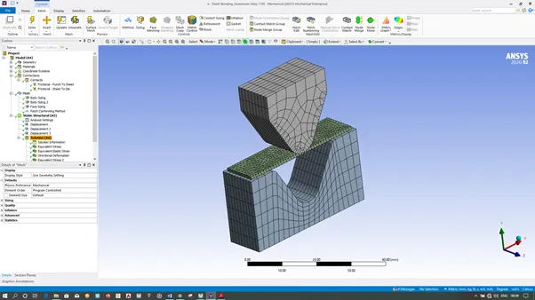
4.2 MESH CREATION
1) Insert Sizing, select the Punch & Die using body filter. Generate 4mm mesh.
2) Insert Sizing, select Sheet using body filter. Generate 1mm mesh.
3) Insert Sizing, select top faces of Die & bottom faces of Punch. Generate 1mm mesh
4) Insert Method, select Sheet using body filter. Define method as Tetrahedrons and generate mesh.
4.3 ANALYSIS SETTINGS
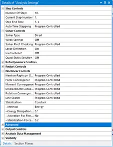
Consider following as the analysis settings for all the 10 steps.
|
STEP CONTROLS Time is an essential parameter in tracking all the analysis even though the model is time-dependent or not. In a static analysis where it is time-independent, the analysis takes place as steps in which the steps are incremented linearly. The beginning time will be 0, and the time for the final load application is 1. If some more load is added, then the time is going to be 2. Here, the time is not considered as minutes or seconds but as a counter or tracker. The substeps respective to the load steps will vary linearly. Large deflection This option helps the solver whether the large deflection, large stain, large rotation happening in the simulation should be taken into account. It is available for static structural and transient structural analysis. Enabling this by ON will help the solver to consider the large strain happening, such as metal forming in a simulation and deflection. SOLVER CONTROLS Solver controls provide some properties based on the analysis type. For both the static structural analysis and transient structural analysis the common properties are ● Solver type ● Weak springs ● Large deflection Solver type Helps in choosing the required solver type for carrying out a simulation. It offers three options, Program controlled: default option. The program automatically chooses the solver based on the model application. Direct: This is one of the solver types where the solver uses a Sparse solver (solver handles a system of equations where the coefficient matrix entries contain mostly zero) to solve the model. Iterative: This type, when chosen, solves the model in PCG (Preconditioned Conjugate Gradient) or ICCG (Incomplete Cholesky Conjugate Gradient) solver. This is mainly used for electric and electromagnetic simulations. NONLINEAR CONTROLS Nonlinear control provides some properties based on their analysis systems. Here, the nonlinear controls for the steady-state, static, and transient structural analyses are discussed. Stabilization: Large displacement problems in a model often faces convergence issues even when the model has small load increments. This convergence issue can be cleared by adding stabilization to the nodes of the model in any degree of freedom. The stabilization is of adding dampers to all the nodes. When those large displacement nodes try to move, the force is added to balance them. It offers some options, OFF: it turns off the stabilization Constant: it activates the stabilization, and the energy dissipation ratio or damping ratio is made constant at every load step. Reduce: it activates the stabilization, and the value is reduced linearly to zero from the specified or calculated value. Energy is the dissipation energy method used for controlling. This is a default setting. The default value is 1.0e-4. Damping is the damping factor method used for controlling. The value must be greater than 0. The stabilization force limit value must be between 0 and 1. The default value is 0.2. |
4.4 BOUNDARY CONDITIONS
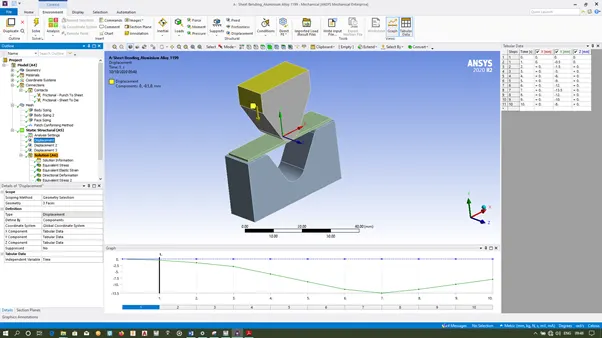
1) Right click Static Structural & Insert Displacement. Select upper & side faces of Punch (3nos).
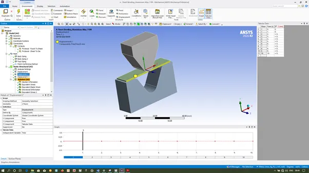
2) Right click Static Structural & Insert Displacement. Select side faces of Sheet (2nos).
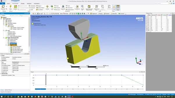
3) Right click Static Structural & Insert Displacement. Select outer faces of Die (5nos).
4.6 SOLUTIONS
CASE 1:
|
|
Aluminium Alloy 1199 |
Copper Alloy NL |
Magnesium Alloy NL |
Comparison |
|
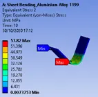
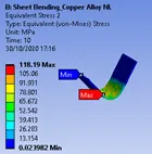
Equivalent stress – Sheet |
 |
 |
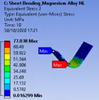 |
1. Since copper is having highest yield strength it requires more force to deform as compared to other materials. 2. Aluminium alloy is the lowest in yield strength and it require less force to deform. |
|
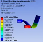
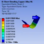
Equivalent elastic strain – Sheet |
 |
 |
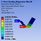 |
1. Since Magnesium is having highest Poisson’s ratio it deforms more as compared to other materials. 2. Aluminium alloy is the lowest in Poisson’s ratio and it deforms less. |
|
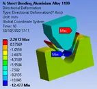
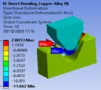
Total Deformation in Y direction |
 |
 |
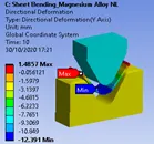 |
1. Due to highest Poisson’s ratio Total deformation in -Y direction higher for Magnesium 2. Due to the highest young’s modulus, Total deformation in -Y direction is less for Copper alloy. |
CASE 2:
|
|
Aluminium Alloy 1199 with friction coefficient to 0.1 |
Aluminium Alloy 1199 with friction coefficient to 0.19 |
Comparison |
|
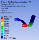
Equivalent stress – Sheet |
 |
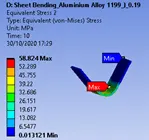 |
After increasing the friction coefficient the stress developed in slightly increased |
|
Equivalent elastic strain – Sheet |
|
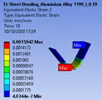 |
After increasing the friction coefficient, found slight decrement in strain. |
|
Total Deformation in Y direction |
|
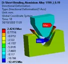 |
After increasing the friction coefficient, found slight decrement in deformation in –Y direction |
CASE 3:
|
|
Aluminium Alloy 1199 with Mesh Size: 1mm |
Aluminium Alloy 1199 with Mesh Size: 0.668mm |
Comparison |
|
Number of Nodes |
17850 |
31532 |
After refining the mesh, found 1.76 times increase in Number of Nods |
|
Number of Elements |
6224 |
14443 |
After refining the mesh, found 2.32 times increase in Number of Nods |
|
Equivalent stress – Sheet |
|
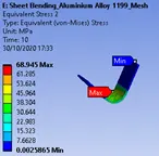 |
After refining the mesh, found 19% increase in maximum stress developed |
|
Equivalent elastic strain – Sheet |
|
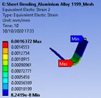 |
After refining the mesh, found 2.2% increase in maximum strain developed |
|
Total Deformation in Y direction |
|
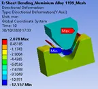 |
After refining the mesh, found 0.6% increase in total deformation in –Y direction. |
- CONCLUSSION
Simulation of sheet bending process conducted with Aluminium Alloy 1199, Copper Alloy NL and Magnesium Alloy NL. From the analysis it is found that Aluminium Alloy 1199 shows good bending properties with less amount of stress generation & less deformation.
Comparison of the simulation is done with different friction coefficient’s, after increasing the friction coefficient, bending properties increased further with decrement in strain.
Mesh refinement done within academic limit of 32K number of nodes/elements. From the analysis found increase in Maximum Stress Developed and no major difference in other results.