Week-7 Challenge: DC Motor Control
1.
Speed Control of a DC Motor Using BJT H-Bridge
- The Bipolar Junction Transistor (BJT) when used for power switching applications, operates as an IGBT. When it is conducting (BJT operating in the saturated region), a forward voltage Vf is developed between collector and emitter (in the range of 1 V). Therefore, the IGBT block can be used to model the BJT device.
- The IGBT block does not simulate the gate current controlling the BJT or IGBT. The switch is controlled by a Simulink® signal (1/0). The DC motor uses the preset model (5 HP 24V 1750 rpm). It simulates a fan-type load (where Load torque is proportional to the square of speed). The armature means voltage can be varied from 0 to 240 V when the duty cycle (specified in the Pulse Generator block) is varied from 0 to 100%.
- The H-bridge consists of four BJT/Diode pairs (BJT simulated by IGBT models). Two transistors are switched simultaneously: Q1 and Q4 or Q2 and Q3. When Q1 and Q4 are fired, a positive voltage is applied to the motor, and diodes D2-D3 operate as free-wheeling diodes when Q1 and Q4 are switched off. When Q2 and Q3 are fired, a negative voltage is applied to the motor, and diodes D1-D4 operate as free-wheeling diodes when Q2 and Q3 are switched off.
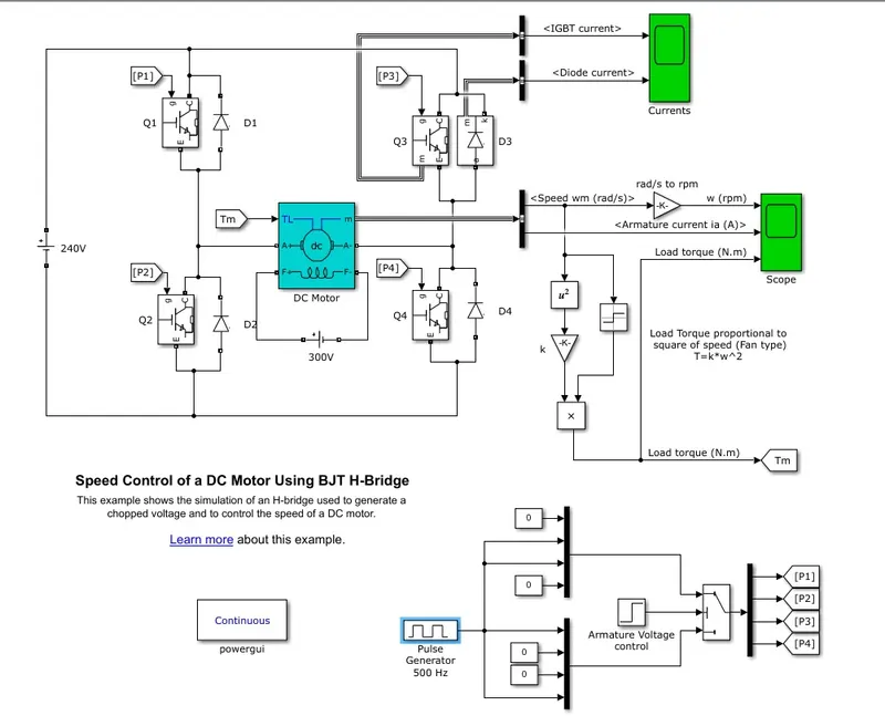
- the model shown above gives the output plots of motor speed, armature current, and load torque, and currents flowing in BJT Q3 and diode D3.
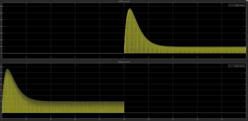
- this plot made for a duty cycle of 75%
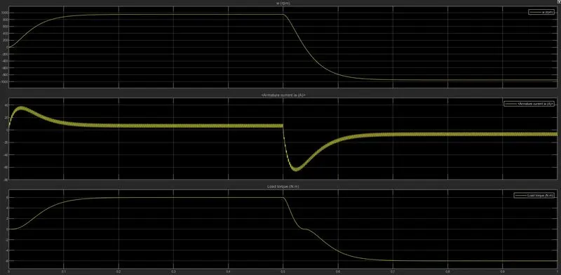
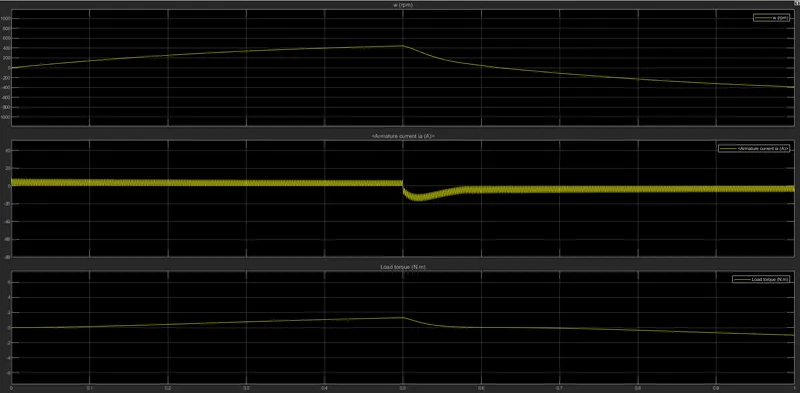
- from the above plot shown you can observe that initially, the motor is running in forward-motoring mode and there is a sudden spike in the armature current( at 0.5sec after the start of simulation) when the armature voltage is suddenly reversed.
armature current = (armature voltage - back EMF)/armature resistance.
- i.e `Ia=(Va-Eb)/(Ra)`
from the relation given above, we can conclude the following.
- whenever the armature stops or slows down to rotate the back emf is very less generated and sometimes even zero i.e the Eb=0 armature current Ia increases drastically from the given equation above.
the armature is slowed down or stopped in the model when there is a reversal in the armature voltage Va, the armature slows down and stops for an instance, and starts to rotate in the opposite direction.
To overcome this effect the only way is to reduce the armature voltage, this can be done by reducing the duty cycle to a lower value.
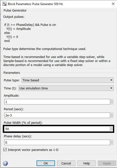
- plot fo a duty cycle of 50%
To overcome the above drawbacks we use.
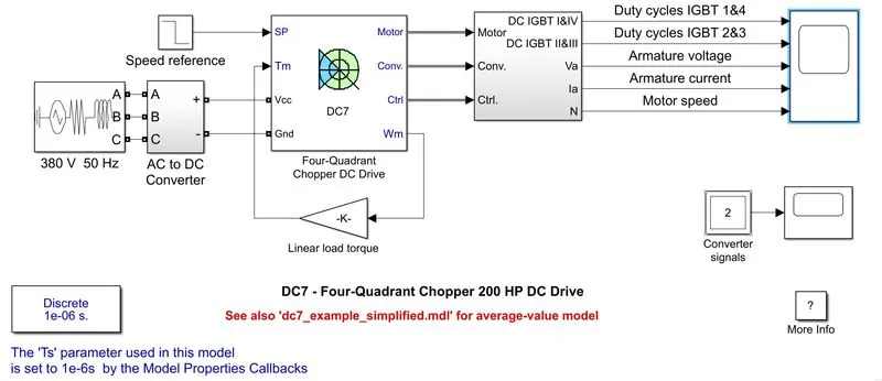
‘The Four-Quadrant Chopper DC Drive (DC7) block’
- The armature voltage is provided by an IGBT converter controlled by two PI regulators. The converter is fed by a 515 V DC bus obtained by rectification of a 380 V AC 50 Hz voltage source.
- To limit the DC bus voltage during dynamic braking mode, a braking chopper has been added between the diode rectifier and the DC7 block.
- The first regulator is a speed regulator, followed by a current regulator. The speed regulator outputs the armature current reference (in p.u.) used by the current controller to obtain the electromagnetic torque needed to reach the desired speed.
- The speed reference change rate follows acceleration and deceleration ramps to avoid sudden reference changes that could cause armature over-current and destabilize the system. The current regulator controls the armature current by computing the appropriate duty ratios of the 5 kHz pulses of the four IGBT devices (Pulse Width Modulation).
- For proper system behavior, the instantaneous pulse values of IGBT devices 1 and 4 are opposite to those of IGBT devices 2 and 3. This generates the average armature voltage needed to obtain the desired armature current. To limit the amplitude of the current oscillations, a smoothing inductance is placed in series with the armature circuit.
Simulation.
- Before starting the simulation, set the initial bus voltage to 515 V via the GUI block ('The Initial States Setting' button and 'Cbus' variable).
- Start the simulation. You can observe the motor armature voltage and current, the four IGBT pulses, and the motor speed on the scope. The current and speed references are also shown.
- The motor is coupled to a linear load, which means that the mechanical torque of the load is proportional to the speed.
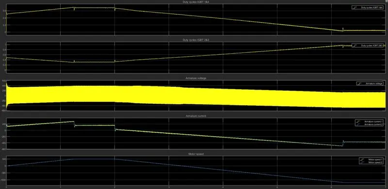
- The speed reference is set at 500 rpm at t = 0 s. Observe that the motor speed follows the reference ramp accurately (+400 rpm/s) and reaches steady-state around t = 1.3 s.
- The armature current follows the current reference very well, with fast response time and small ripples. Notice that the current ripple frequency is 5 kHz.
- At t = 2 s, speed reference drops to -1184 rpm. The current reference decreases to reduce the electromagnetic torque and causes the motor to decelerate with the help of the load torque.
- At t = 2.2 s, the current reverses to produce a braking electromagnetic torque (dynamic braking mode). This causes the DC bus voltage to increase.
- At t = 3.25 s, the motor reaches 0 rpm and the load torque reverses and becomes negative. The negative current now produces an accelerating electromagnetic torque to allow the motor to follow the negative speed ramp (-400 rpm/s). At t = 6.3 s, the speed reaches -1184 rpm and stabilizes around its reference.
|
|
| Armature current sudden spike is controlled here since the applied armature voltage is under control using regulators and choppers. | armature current sudden spike is controlled only by reducing the armature voltage duty cycle. |
| there are current and speed regulators. | there are no such regulators. |
| high switching frequency since we are using IGBT | low switching speed due to BJT |
| to change the rotation of the motor like forwarding and reverse, the signal is interrupted with one another. | to change the rotation of the motor the polarity of the current is changed |
|
it operates in 4-quadrants
|
it operates in 2-quadrants
|
2.
2-quadrant chopper
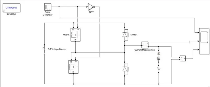
Type C chopper is obtained by connecting type –A and type –B choppers in parallel. We will always get a positive output voltage V0 as the freewheeling diode FD is present across the load. When the chopper is on the freewheeling diode starts conducting and the output voltage v0 will be equal to Vs. The direction of the load current i0 will be reversed. The current i0 will be flowing towards the source and it will be positive regardless of the chopper is on or the FD conducts. The load current will be negative if the chopper is or the diode D2 conducts. We can say the chopper and FD operate together as a type-A chopper in the first quadrant. In the second quadrant, the chopper and D2 will operate together as type –B chopper.
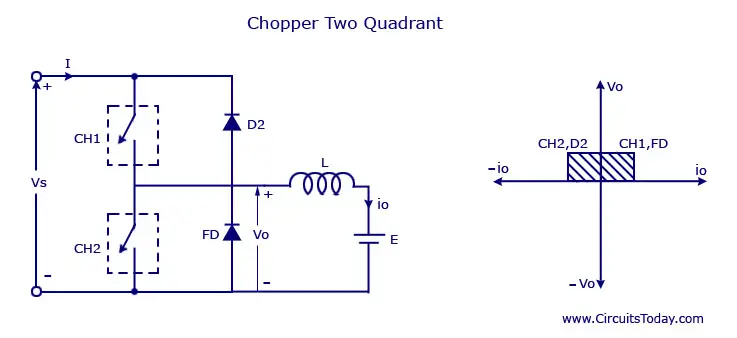
The average voltage will be always positive but the average load current might be positive or negative. The power flow may be living the first quadrant operation ie from source to load or from load to source like the second quadrant operation. The two choppers should not be turned on simultaneously as the combined action may cause a short circuit in supply lines. For regenerative braking and motoring, this type of chopper configuration is used.
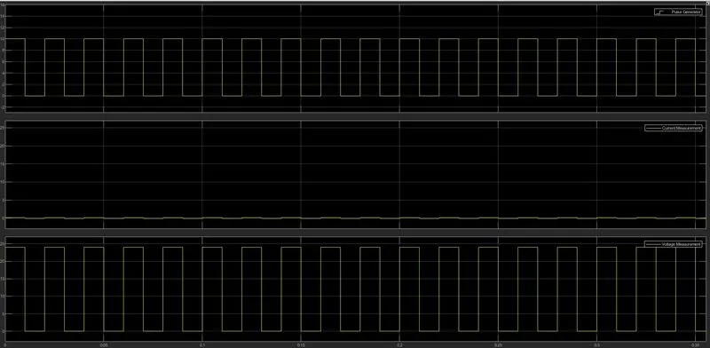
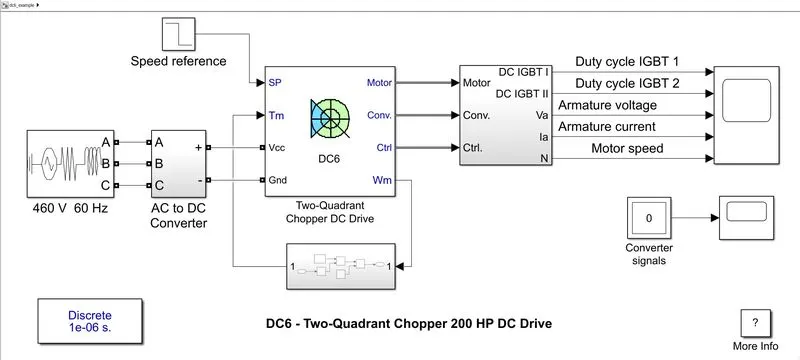
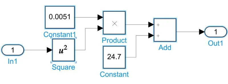
further from this operation, we can build an EV model using our own speed-torque equation using a two-quadrant chopper as follows
speed-torque equation.
3.
Operation of BLDC( brushless DC motor)
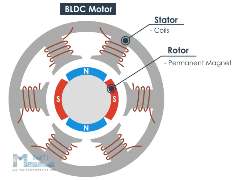
the above figure explains the construction of the BLDC motor, brushless DC motor as a wide range of advantages over not only to DC motor but to any other motor out there.
- BLDC motor uses a permanent magnet as its rotor and windings supplied with DC as the stator.
Working:
- working of a BDLC is very simple it just works on the principle that like poles attract and unlike poles repel.
- when a DC is passed through the stator windings there will be a magnetic field induced and this fields interact with a permanent magnetic field
- when a current in the windings is clockwise the stator acts as a south pole and similarly when the current is in an anti-clockwise direction it acts as a north pole.
- to make sure there is smooth rotation the direction of current in each pole will be changing simultaneously making sure the torque is used appropriately.
- to get to know the location of the south pole of the permanent magnetic so that we get to know which pole to excite we use an inverter.
- the function of the inverter is to sense and control the excitation of the poles with the appropriate direction of the current.
- thus the rotor moves as shown in the image below
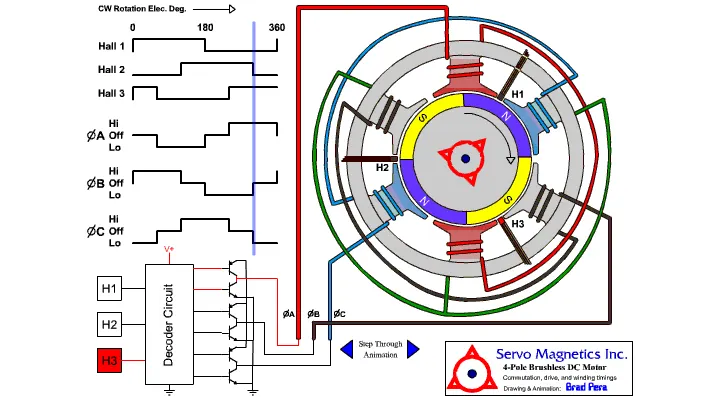
the above figure shows how the controller is exciting the respective poles to achieve the smooth rotation of the rotor.