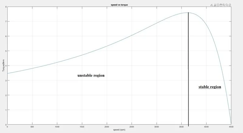
Induction Motor characteristics
1.
induction motor operation is similar to the clutch
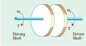
- torque on the driving shaft = torque on the driven shaft.
- In fact, these two torques are actually one and the same torque, because the torque is caused by friction between the discs and it is true whether the clutch is slipping or not. Let ω1 and ω2 be the angular velocities of the shaft when the clutch is slipping.
`omega_m=omega_ms(1-s)` --------> for induction moto`
`omega_2=omega_1(1-s)`-------> for clutch `
input power= Tw1
output power = Tw2
loss = input power - output power
= `omega_1t-omega_2t`
= Tw1- T(w1(1-s)
= T( w1-w1+w1*s)
loss = T(w1*S)
therefore
rotor copper loss = s*w1T
- Rotor Cu loss = slip × rotor input
2.
motor-load system fundamental equation is given by:
`T-T_1=d/dt(Jomega_m)= J(domega_m)/dt - omega_m(dJ)/dt`
the above equation is applicable to variable inertia drive like rel winders, industrial robots, etc.
for drives with constant inertia, dJ/dt=0
`T=T_1+J(domega_m)/dt`
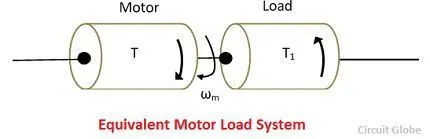
the above equation shows that the motor torque is counterbalanced by load torque and dynamic torque.
the dynamic torque J dWm/dt is present only during the transient operation i.e when there are sudden changes in the systems like acceleration, braking, speed reversal.
the time is taken for the motor to attain the steady-state operation and the energy loss can be considered while calculating the starting time.
given:
- J=10 kg-m2,
- Tm = 15 + 0.5w
- Tl=5+0.6ωm
for the steady-state condition is Tl=Tm
therefore we need to equate them to find Wm from the equation.
15 + 0.5`omega_m`= 5+ 0.6`omega_m`
0.1`omega_m`= 10
therefore Wm= 100rad/sec
now, in order to attain equilibrium the final speed needs to be considered, theoretically to reach equilibrium it takes infinite time so hence in practice we consider 95% of the final speed (Wm)
hence, we need to integrate the below equation taking the limits of speed as Wm1=0 to Wm2= 95(i.e 95% of Wm)
`dt=(Jdomega_m)/(Tomega_m-T_lomega_m)`
`t=Jint_(wm1)^(wm2) (domega_m)/(Tomega_m-T_lomega_m`
`t=10int_0^95 (d(omega_m))/(15-0.5(omega_m)-5+0.6(omega_m)`
`t=int_0^95 1/(1-0.01omega_m) domega_m`
`t=[-100ln|1-0.01omega_m|]_0^95`
t=299.57 sec.
3.
given
A drive has the following equations for motor and load torques:
- Tm=(1+2ωm)
- Tl= 3 √ωm
for the steady-state condition or at equilibrium `T_m=T_l`
`1+2omega_m=3sqrt(omega_m`
squaring on both sides and solving the quadratic equation
we get
`omega_n=0.25`
`omega_m=1`
we know that
`(dT_l)/(domega_m)-(dT_m)/(domega_m)>0`
if dw>0 i.e if the speed is increasing w.r.to time then Tl>Tm
- the load torque needs to be greater than the motor torque so that it can prevent the motor from reaching an infinite speed or losing stability due to high speed
if dw<0 i.e if the speed is decreasing w.r.to time then Tl<Tm
- the motor torque needs to be greater than load torque in order to avoid the motor speed to zero, which would happen when there is very little torque is applied to the motor, and due to higher load torque, the speed decreases gradually. and hence this would also be an unstable condition.
`(d(3sqrtomega_m))/(domega_m)-(d(1+2omega_m))/(domega_m)>0`
`3/(2sqrtomega_n)-2>0`
therefore:
when;
`omega_m=0.25`======>stable (the above equation is greater than zero)
`omega_m=1`=======>unstable(the above equation is greater than zero)
4.
R1=0.645---->stator resistance
R2=0.334----->rotor resistance
x1=1.106----->stator reactance
x2=0.464----->rotor reactance
speed-torque characteristics for frequency control method :
the plot can be made using these formulas:
the equation of torque is given by:
`T=3/(N_(s)) ((V_(rms)^2)*(R_2/s))/((R_1+1/s R_2)^2+(X_1+X_2)^2`
the equation of slip is given by:
`s=(N_s-N_r)/N_s`
the equation of synchronous speed is given by:
`n_s=(120f)/p`
clear all
close all
clc

p=4; %no. of poles
s=linspace(0,1,100); %slip
R1=0.645; %stator resistance
R2=0.334; %rotor resistance
x1=1.106; %stator reactance
x2=0.464; %rotor reactance

k=linspace(0.7,2,5); %k is for controlling frequency
v=400/sqrt(3); %volatge per phase

for j=1:5
    f=50.*k(j);
    wms=(120*f)/p; %synchronous speed calculation

    for i=1:100
        wm(i)=(1-s(i))*(wms);%rotor speed calculation
        denom=((R1+((R2)./(s(i)))).^2)+((x1+x2)^2); %denominator in torque equation
        T(i)=((3/wms)*((v^2)*(R2)./s(i)./(denom)));
        T(1)=0;
    end

plot(wm,T)
hold on
xlabel('speed (rpm)')
ylabel('Torque(N-m')
end
grid on
title('speed vs torque')
- here we are calling it frequency control because using the frequency we are changing the motor speed corresponding torque is obtained using the equation shown above
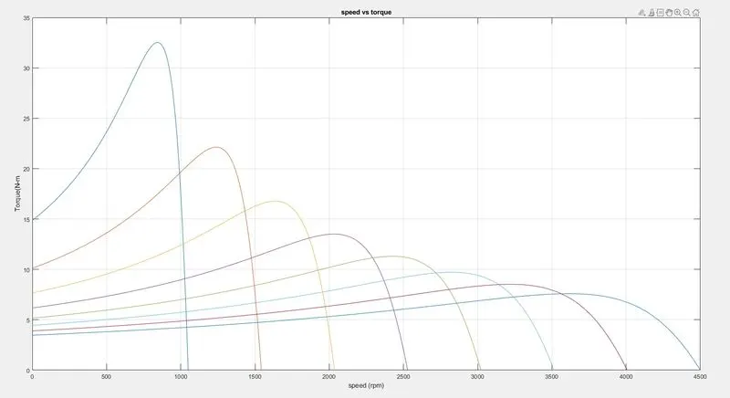
the stability of the plot as shown below