Week-11 Challenge: Braking
1.
braking energy required for the drive cycle:
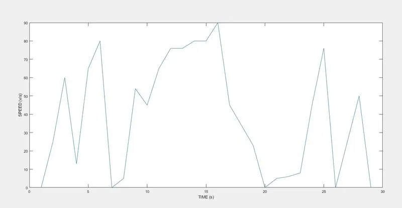
A very known principle of law conservation of energy states that energy cannot be created nor be destroyed hence using this principle we calculate braking energy as follows:
initially, the vehicle will be moving i.e it will be having some kinetic energy when the brake is applied the speed of the vehicle reduces thereby decreasing the kinetic energy the energy will be lost in the form of heat in brake pads, if the vehicle is having regenerative braking then the energy is converted into electrical energy and would be fed back to the battery.
therefore from the above discussion, we can conclude that the kinetic energy converted is itself the braking energy required.
braking energy = `1/2M(V_f-V_i)^2`
Vf =is the final velocity,
Vi =is the initial velocity.
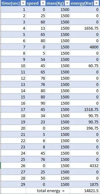
using the above formula braking energy is calculated for the drive cycle shown above.
the total braking energy is =14821.5 Kilowatts.
2.
the electric motor can’t develop braking torque at high!!
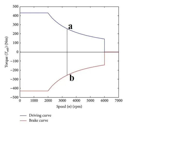
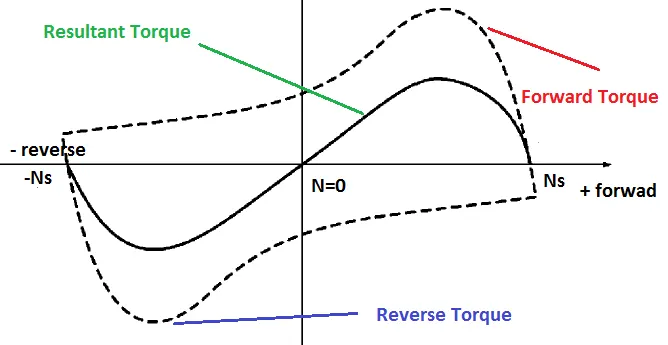
the below plot shows the speed-torque characteristics of the induction motor from the plot we can conclude the following results:
- when you observe the drive curve you can notice that starting torque is around 420(Nm) at speed= 0 (rpm), this indicates there is maximum torque supply during the staring of the vehicle.
- till 2000 rpm of speed the torque is maximum and constant because even the voltage is increasing with an increase in frequency beyond this point the voltage stops increasing beyond the rated value and hence the torque starts to decrease but with increasing frequency the speed increases.
- braking characteristics are just symmetrically opposite as shown below. we can observe that at higher speed the torque supply decreases from the motor i.e the torque is reduced to 300 (Nm) from 420(Nm) here the negative signs indicate that the torque is in opposite direction to the movement of the vehicle.
- the vertical line from 'a' to 'b' indicates that there is braking at 3200 rpm, here the torque demand is very high because the speed is more, and hence more force is required to stop the vehicle but from the plot, we can observe that the torque supply is low.
from the above points, we can conclude Why an electric motor can’t develop braking torque at a high speed similar to starting.
How electric and mechanical brakes are coordinated:
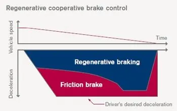
we now know that an electric motor can’t develop braking torque at a high speed and therefore an alternative as to be done to provide the required torque demand for the braking can be done using the mechanical brakes. and hence the electric and mechanical brakes are coordinated as follows:
- from the image given below, we can observe that whenever the speed is high in order to meet the torque demand for braking we are using mechanical brakes like frictional brakes to slow down the car.
- when the speed is low torque demand for braking is low and hence there will be no need for mechanical braking the whole torque is provided by the regenerative braking.
to implement the above idea there are two methods:
series: in this case at each instance there will be one kind of braking in use that is it can be mechanical or electrical depending on the speed of the vehicle.
parallel: in this case at each instance there will be both kinds of braking in use that is mechanical and electrical depending on the speed of the vehicle.
3.
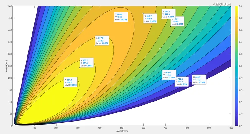
The contour of given motor speed, torque, and efficiency values:
every motor contour can be achieved by modelling the losses to get the value of losses we need to the constants these constants are provided by the company or even can be found experimentally.
the different kind of losses associated with the motor is:
- copper loss = `K_c*T^2`
- iron loss = `K_i*omega`
- windage loss = `K_womega^3`
- constant loss = Cm
the total loss is = `K_cT^2+K_iomega+K_womega^3+C_m`
output power = speed*torque
therefore, efficiency= outpower/input power = output power/(output power +total losses)
given:
kc=0.1------> copper loss constant
ki=0.001-------> iron loss constant
kw=0.0001-------> windage loss constant
cm=25-------> motor loss constant
speed and torque will be taking random for the specified range mentioned below:
syntax:
clear all;
close all;
clc;

%difining speed and torque
torque= linspace(0,500,500); %input torque
speed= linspace(0,1000,300); %input speed

%motor constants
kc=0.1;     %copper loss constant
ki=0.001;   %iron loss constant
kw=0.0001;  %windage loss constant
cm=25;      %motor loss constant

%2-D grid for speed and torque
[w,T]=meshgrid(speed,torque);

powerout= w.*T;     %output power
c_loss= kc*(T.^2);  %copper loss
I_loss=ki*w;        %iron loss
W_loss=kw*(w.^3);   %windage loss

total_loss= ((T.^2).*kc)+(ki.*w)+(w.^3).*kw+cm;

inputpower= powerout + total_loss;

efficiency= powerout./inputpower;

%efficiency level for contouring
E1=[0.70,0.72,0.75,0.77,0.79,0.80,0.81,0.82,0.83,0.84,0.85,0.86,0.87,0.88,0.89,0.90];

%plotting the efficiency w.r.to speed and torque
contourf(w,T,efficiency,E1);
colorbar
xlabel("speed(rpm)");
ylabel("torque(Nm)");
the output plot is given by :