Week 9 Challenge
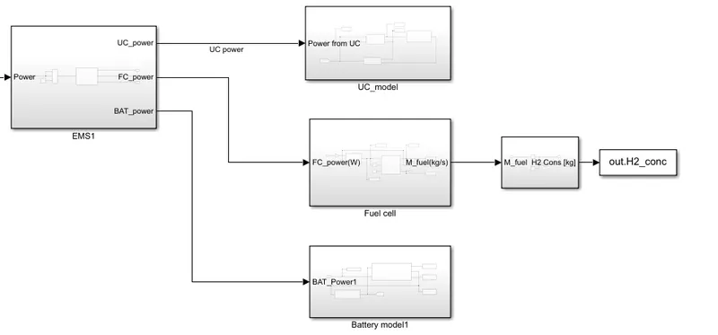
The software used to develop the model in MATLAB/Simulink was developed by MathWorks. Inc. Simulink which is a part of the package is the tool used for modeling the vehicle along with its components and for developing the PMS strategy. Simulink is a tool that provides libraries with different functions associated with different kinds of libraries. These libraries provide blocks that are used to create a block diagram for modeling and simulating systems. All the systems in this FCHEV model have been modeled using these library blocks. The initial model of FCHEV upon which this model was developed contained a battery and fuel cells. It had a basic PMS which worked based on power thresholds as the main criteria for distributing power among the components keeping in check the lower limit of battery SOC. The new model contains an UC in the ESS system and a redesigned PMS
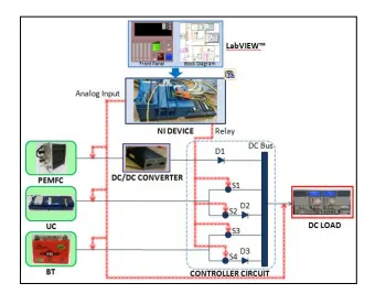
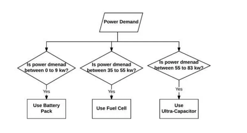
The powertrain block consists of many subsystem blocks that collectively model the entire powertrain. The major subsystems inside the powertrain block are listed below:
1. Fuel Cell System
2. Energy Storage System
3. Controller
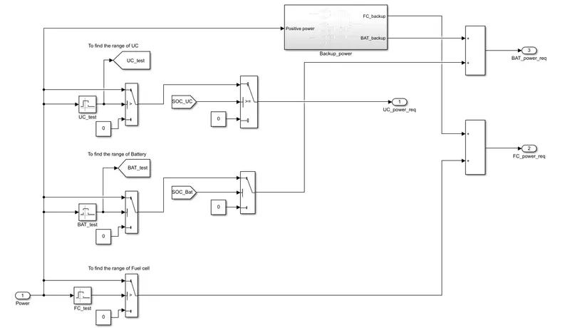
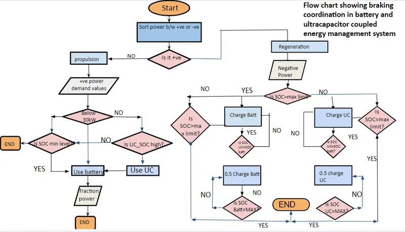
Although there is a huge amount of power that can be generated when the motor turns into a generator when braking at high speeds, usually there is a limit to the amount of current that can be pushed
into the battery. UCs have a much higher limit of acceptable charging current. In the absence of UC, the excess current above the acceptable charge current of the battery, would have to be discharged as heat through a resistor. So, it is important to characteristics of UC to the maximum which in turn will help protect the battery from excess charge current also enhancing the efficiency of the electric system at the same time. With the UC in the ESS, almost all the regenerative current can be utilized based on the SOC of the components. With this idea in mind, a dynamic SOC-based regenerative control strategy was developed
As explained earlier, Initial Vehicle Motion (IVM) requires high power demand. Therefore, the torque supplied by the electric motor directly translates the amount of current being pulled by the UC. Figure 50 shows how the UC assists in the stop-and-go situations that pose high transient current demand and thus handle most of the high power demand situations. Once the vehicle is in motion, its power demand goes down and once it’s in the range that the battery can handle the vehicle can draw current from the battery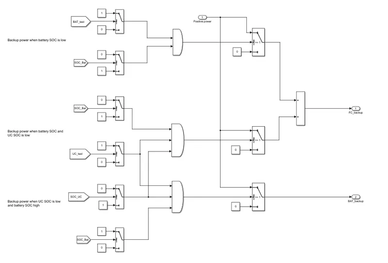
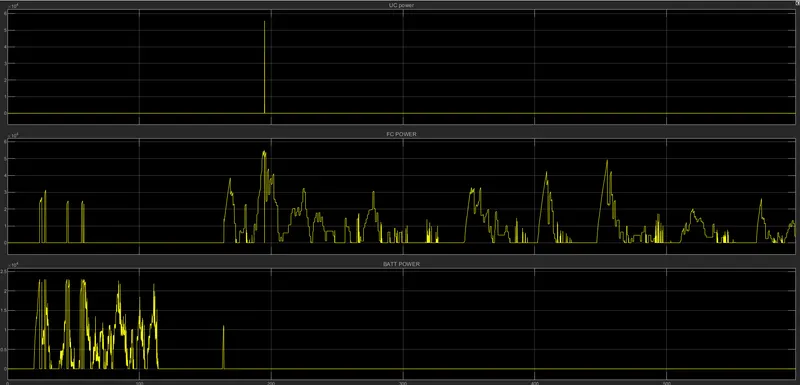
As explained earlier, Initial Vehicle Motion (IVM) requires high power demand. Therefore, the torque supplied by the electric motor directly translates the amount of current being pulled by the UC. Figure 50 shows how the UC assists in the stop-and-go situations that pose high transient current demand and thus handling most of the high-power-demand situations. Once the vehicle is in motion, its power demand goes down and once it’s in the range that the battery can handle the vehicle can draw current from the battery
it can be seen that even earlier the dependence on battery current was high, but adding a UC has two benefits. First, it reduces the maximum and the average current drawn from the battery. This helps in maintaining the SOC and reduces the number of charge-discharge cycles improving the state of health of the battery. Secondly, there are instances when the current from the battery is zero which wasn’t the case with previous logic. This again reduces the power drawn from the battery while improving the performance of the car since UC can handle that higher current demand much better
Without the UC, it's clearly visible that there are many spikes that occur on the power demand profile of the battery as seen in Figure 55. Also, there are several peaks on the power
demand profile. So, adding the UC levels out the power demand from the battery using itfor low power high energy kind of situations which it's suitable for. The high-power peaks seen in the figure are redirected to UC in the control strategy thus making this strategy more efficient
Model is attached here