STATE FLOW MODEL OF WASHING MACHINE AND GEAR SHIFT
washing machine
Aim:
Implement control logic of a “washing machine” using State flow as per given sequence
Description:
- If the power supply is available, the system gets activated
- If the Water supply is not available, stop the process & indicate through LED
- Soaking time should be 200s followed by Washing time of 100s.
- Then rinsing happens for the next 20s & dryer runs for 50s
State flow model:
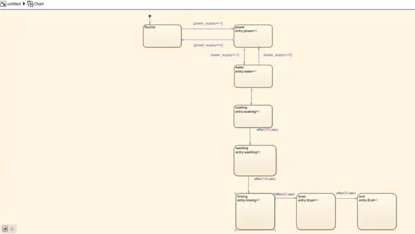
Working:
- When the power supply is ON using the toggle switch the system gets activated. here the toggle switch is connected to the power supply.
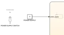
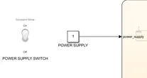
- If in case the water supply is not ON, LED will turn ON indicating to turn ON the water supply
- If the water supply is ON the condition gets satisfied and moves to the next state i.e., soaking
- Soaking is done for a duration of 200secs as mentioned and the logic is implanted using the event name “after” so when the condition is satisfied it goes to the next state.
- And so on goes to the end block by satisfying all the conditions mentioned and the process is completed and this is indicated by the LED using the value of “End”.
- The water supply LED is ON indicating the user to turn ON the water supply as shown below.
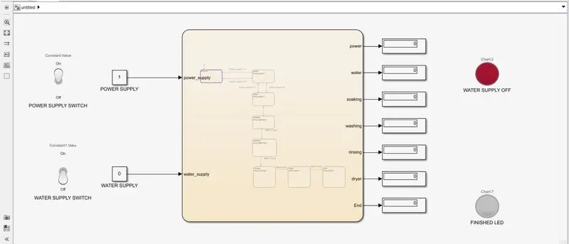
- finished LED is ON indicating the whole process is completed.
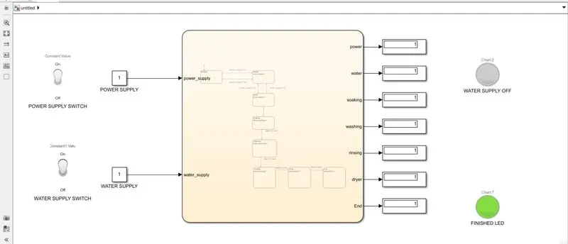
- and also you can observe the display block where the value=1 is indicating that the particular process is completed.
Symbols specification:
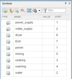
The power supply and the water supply are specified as input and the rest all are output.
Result:
Implementation of the control logic of a “washing machine” using State flow as per given sequence and conditions is as shown above.
Gear shift
Aim:
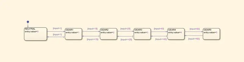
Make a Simulink chart for the “Gear shift” logic as per below conditions:
Speed Range(kmph) Gear
0 to 15 1
16 to 25 2
26 to 40 3
41 to 60 4
Above 61 5
Give speed input while the simulation is running & display the gear number.
Description and working:
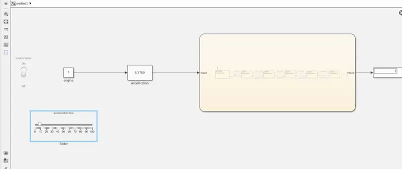
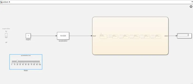
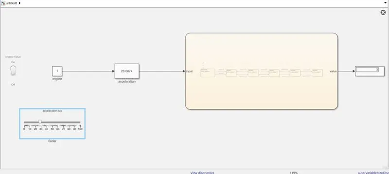
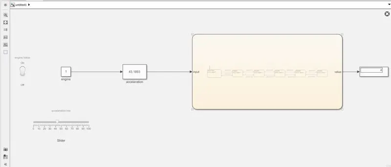
- turn ON the engine using the toggle switch provided
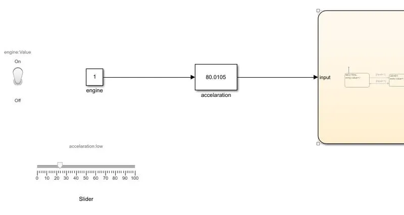
- the slider is provided to increase or decrease the acceleration during the run time
- and the gear shifted depending on the speed that is given in the input
- the shifting of gear takes place only when the condition mentioned is satisfied and state flow changes its state depending on the conditions
- the gear that is running is displayed in the display block.
- gear=1(0 to 15 ), speed=8.3kmph
- gear=2(16 to 25), speed=19.4kmph
- gear=3(26 to 40), speed=28kmph
- gear=4(41 to 60), speed=43.1kmph
- gear=5(Above 61), speed=91.0kmph
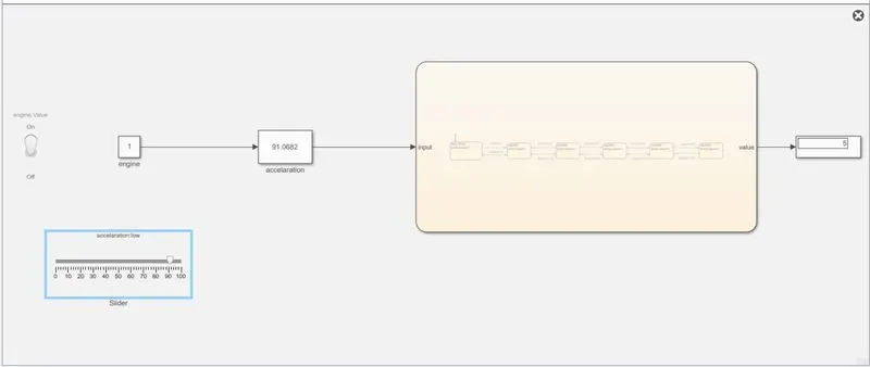
result:
By the above description and Stateflow control logic gear shift process implementation is understood