control of duty cycle on power electronics circuit and induction motor control methods
1.power electronics circuits
power electronics circuit is the major reason for the advancement in the technology where the losses are reduced traditionally we were using resistance method to convert anything but due to use of switching property of power electronics we can achieve greater efficiency without much loss.
power: deals with static or rotating power equipment for transmission generation and distribution of electrical energy (motor)
control: steady-state and dynamic characteristics of closed-loop systems(speed)
electronics: solid-state devices and circuits for signal processing to meet the desired control objective.
therefore; the application of solid-state electronics for control and conversion of electrical power is called power electronics.
they are efficient because there are no resistance losses that occur. After all, the required voltage is achieved by switching off and on the power switches.
The major power conversion devices in an EV are the charger, inverter, and DC-DC converter, and, as is the case with the traction motor, it is difficult to nail down an average efficiency level for any of them, because they all operate at wildly different power levels. Also, as with the traction motor, some losses are fixed regardless of load, while others are linearly or exponentially proportional to load.
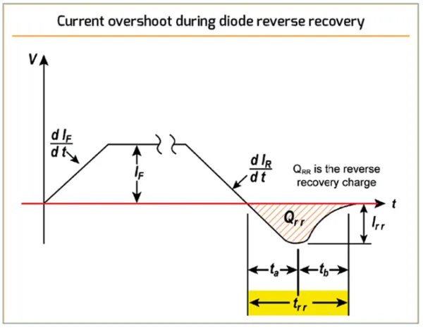
there are three types of losses :
- Conduction Power Loss of switch.
when the transistor is off, it carries a leakage current. however, since the leakage current is quite small and does not vary significantly with voltage, it is usually neglected and thus the transistor power loss is essentially zero.
when the transistor is on, it has a small voltage drop across it. the voltage is called the saturation voltage. the transistor power dissipation or conduction loss due to saturation voltage
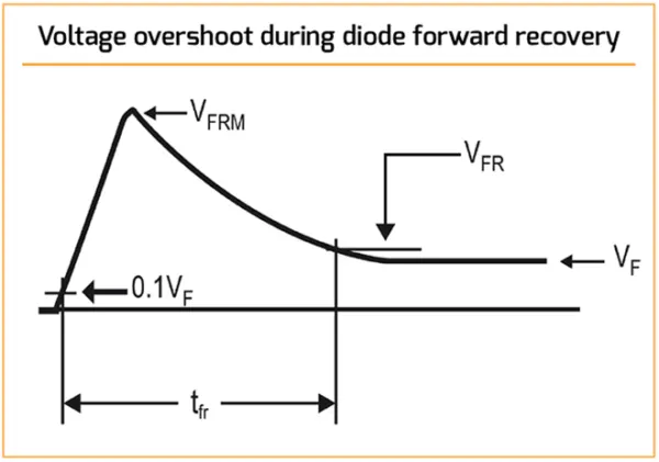
- Switching Power Loss of switch.
there are losses from overlapping voltage and current whenever a device is transitioning between conducting and blocking (or vice versa) – that is, switching – and these can absolutely dominate the loss budget if devices and circuits/conditions aren’t chosen carefully. Unlike conduction and blocking losses, however, it is entirely possible to eliminate switching losses with appropriate circuit techniques, but at a cost in complexity, and perhaps, in reliability as well.
adding up all the energy lost during the switching transitions of one switching period:
`W_t=W_(on)+W_(off)+W_D+W_C+W_L+...`
average switching power loss is
`P_(sw)=W_tf_(sw)`
total convertor loss can be expressed as
`P_(loss)=P_(cond)+P_(fixed)+W_tf_(sw)`
where `P_(fixed)`=fixed losses (independent of load and switching frequency)
`P_(cond)`=conduction losses
usually, the losses in the power electronics circuit are higher when the frequency is higher.
- blocking(or reverse leakage).
Losses incurred from leakage current when the device is supposed to be off are another potential source of misery for the unwary engineer, though they are much more easily avoided if one doesn’t tempt fate by operating the device at high temperatures and/or close to its rated voltage. Once again, pn junction diodes have the advantage over Si-barrier Schottkys, though the gap is not quite so wide for SiC types.
2.
Simulink model for generating pulses for a simple power converter circuit
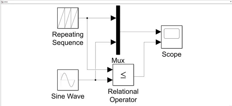
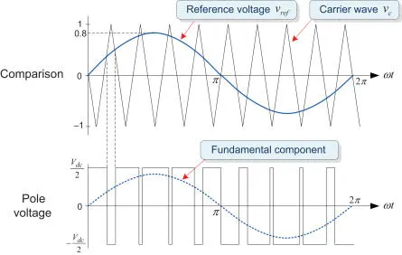
The above model shows a generation of pulse width modulation signal.
- here the carrier wave is the repeating sequence and reference voltage is the sine wave.
- with the help of a relational operator we get the desired pulses, relational operator compares both signals given as input and converts the reference sinusoidal signal into pulses.
- here the pulses generated represent duty cycles for the power converter.
- Duty cycle is the ratio of time a load or circuit is ON compared to the time the load or circuit is OFF. The duty cycle, sometimes called "duty factor," is expressed as a percentage of ON time. A 60% duty cycle is a signal that is ON 60% of the time and OFF the other 40%.
- hence by controlling the duty cycle we can have control over the output voltage.
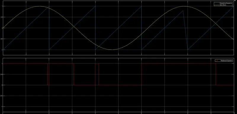
the above results are plotted below as shown.
- here you can observe that pulse is high that is ON when the reference signal is above the value of the carrier signal and it is OFF when the reference signal is below the carrier signal.
Simulating buck converter using the above-generated pulse
the above-generated pulse is given here as the gate pulse for the MOSFET switch.
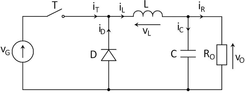
A buck-converter is a power electronic circuit whose main application is to step down higher voltage into lower voltage, it is similar to a step-down transformer but here we step down the DC signal.
some of its practical applications are as follows:
- Point of Load Converters - Used to drive high current loads efficiently. Usually used in PCs and Motherboards.
- Battery Chargers - FOr mobile phones, laptops, and power banks.
- Solar chargers
- To drive BLDC motors.
working;
A buck converter is a DC/DC power converter that steps down the voltage from its input (source) to its output (load). In continuous conduction mode (current through the inductor never falls to zero), the theoretical transfer function of the buck converter is:
`V_o/V_i=D`
where D is the duty cycle. duty cycle lies between 0-1.
- the power switch we are using is MOSFET which has a very high switching frequency.
- when the switch is turned ON the diode becomes reverse bias and the current flows through the inductor and charges the inductor initially and hence there is less voltage across output which is measure across the resistor.
- when the switch is OFF the diode becomes forward bias and starts conducting and the energy stored in the inductor starts discharging, therefore, the current in the circuit never tends to zero but the voltage is reduced.
- the capacitor is given to control and limit the surge in the current.
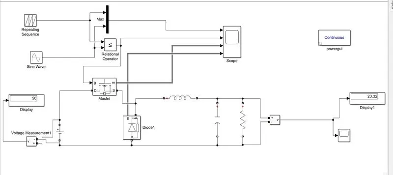
the above model uses the pulse generated from PWM and the same pulse is given to the MOSFET and hence the generated pulses control the switching timing and frequency.
- for the input of 50V, we are getting an output voltage of 23.32V as shown above because it is the step-down dc-dc converter.
- we can change the output value by changing the duty cycle, the duty cycle is varied using the reference signal using which we are generating the gate pulses.
- the output plots are shown below for the above-given model.
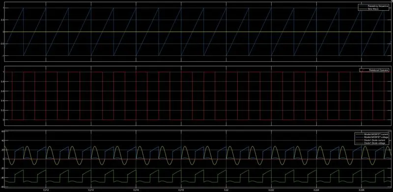
- here you can observe that the pulses generated are almost half of the input signal this indicates the duty cycle is around 50% and hence the output voltage is half of the input volatage.
- also, you can observe the currents and voltages across diodes and MOSFET.
3.
difference between VFD and Vector control drive.
variable frequency drive(VFD)
- this method is a traditional method used for any motor control by the name itself, we can say that the drive is controlled using the frequency it also called VVVF i.e variable voltage and variable frequency control.
- here to increase the torque, `V/fpropphipropT` we make use of the voltage i.e since the voltage is directly proportional to torque as shown in the formula we can achieve greater torque by increasing the voltage but speed cannot be achieved by increasing the voltage.
- to achieve the required speed, we need to change the frequency i.e frequency is directly proportional to the speed the equation is given by `N_s=(120f)/p` where Ns is the synchronous speed of the stator.
- `V_(constant)/(fdarr)=phiuarr=I_phiuarr=theta_odarr=costhetadarr` from this equation we can say that increasing the frequency alone leads to a decrease in the power factor which in turns decreases the power and also draws a large magnetizing current. therefore to keep flux constant and just vary the frequency, we will have to decrease the voltage also in order the maintain the fraction at a constant value.
from the two equations, the relation between torque, slip, speed, and voltage can be given as
=`Tprop(sV^2)/f`
the above equation can be modified as
=`T=(V/f)^2(N_s-N_r)`
therefore
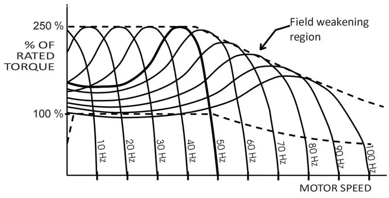
from the above, plot we can conclude the following,
- there are two types of region first part is the constant torque region and the second part is the constant power/voltage region also know as the field weakening region.
- during the constant torque part for the torque to be constant, we have to maintain the `V/f`ratio constant hence from the explanation we can conclude the initial part of the plot is the constant torque region.
- but during the starting torque we know that Nr is zero and therefore slip = 1 and from the equation `Tprop(sV^2)/f` we can conclude that increase in frequency decreases the starting torque.
- the voltage can be increased only till rated voltage beyond that it's not advisable to increase to look after the safety of the system and hence the increase in frequency will decrease the torque as shown in the plot.
limitations of the V/f method or VFD
- flux and current cannot be controlled independently because `T=Iphi` i.e when stator current 'Is' is varied even the flux is varied.
- stator drop compensation.
- this method cannot be used in EV applications because when there is limited charge in the battery the torque decreases due to low supply voltage.
vector control drives working is as shown below
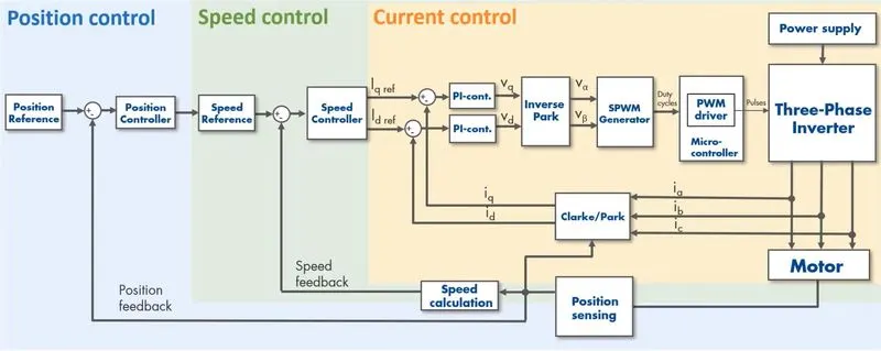
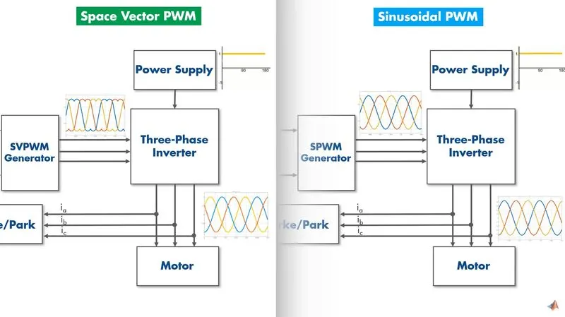
- both the speed and torque of the motor are controlled using the vector control method by using space vectors.
- by dividing the stator current(Is) into its vector component Iq and Id we analyze and regulate them depending upon the speed and torque required
- using Clarke and park transformation we divide stator current as quadrature current(Iq) and direct current(Id).
- the magnitude of stator currents required is measured using where they are compared with the output of the motor.
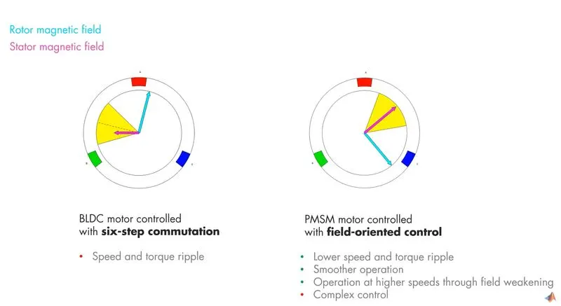
- to achieve maximum torque, we need to make Is(stator field) and reference(rotor field) at 90 degrees to each other hence need to make Id=0 then only the Iq component remained which will provide the maximum torque.
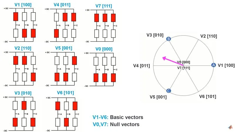
- space vector angular position is controlled by switching between basic vectors.
- space vectors magnitude is controlled by switching between basic and null vectors.
by controlling space vector angular position and space vector magnitude we can achieve the required speed and torque.