Project-1: Powertrain for aircraft in runways
Objective:
1. Search and list out the total weight of various types of aircraft.
2. Is there any difference between ground speed and airspeed?
3. Why is it not recommended to use aircraft engine power to move it on the ground at the Airport?
4. How an aircraft is pushed to the runway when it's ready to take off?
5. Learn about take-off power, tire design, rolling resistance, tire pressure, brake forces when landing.
6. A. With necessary assumptions, calculate the force and power required to push/pull an aircraft by a towing vehicle.
B. Develop the model for the calculated force and power using Simulink.
7. A. Design an electric powertrain with the type of motor, its power rating, and energy required to fulfill aircraft towing application in Simulink. Estimate the duty cycle range to control the aircraft speed from zero to highest. Make all required assumptions. Prepare a table of assumed parameters. Draw a block diagram of the powertrain.
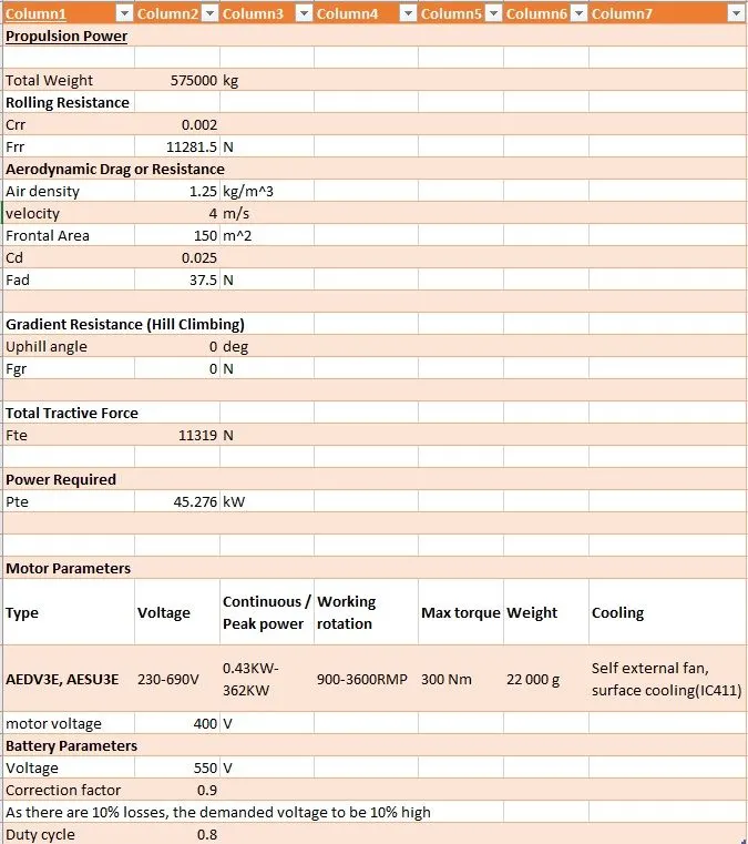
B. Also, Design the parameters in an excel sheet.
Solutions:
1.
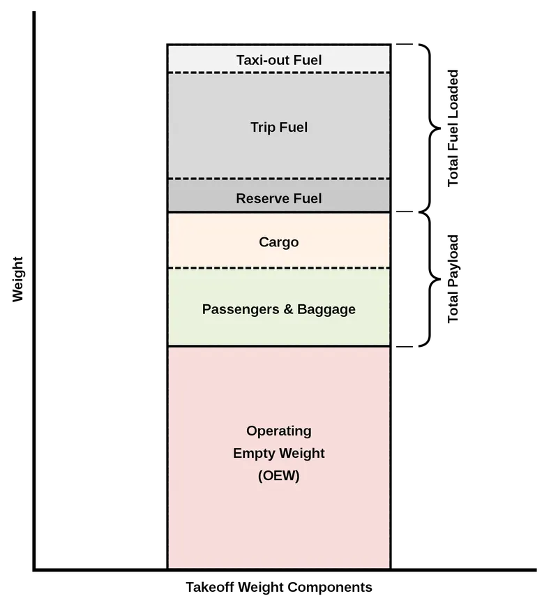
the weight in any aircraft is distributed as follows:
The different types of aircraft are as follows:
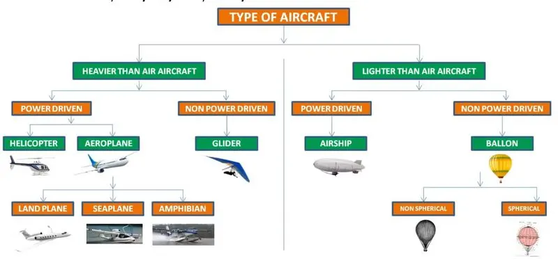
The total weight of various aircraft is given as follows:
Aircraft come in numerous weight categories and can accommodate a variety of tasks, from delivering heavy objects to remote construction sites, to carrying water during the fire season. In most cases, the bigger the aircraft, the heavier it will be. However, a heavier aircraft will need a more powerful propulsion system to generate and maintain lift. Due to the flight characteristics of the aircraft, one would think that they must be pretty light. However, depending on the configuration, they may be quite heavy.
Helicopter:
A helicopter can weigh as little as 298 pounds (135 kg), up to as much as 33,230 pounds (15,070 kg), in empty weight. The weight of a helicopter varies by the type, model, and primary use intended for the aircraft.
Airplane:
The Boeing 737-800 is an example of an average-sized airplane. It has a maximum takeoff weight of about 80,000 kg (175,000 lbs). This includes the weight of the plane, which is about 41,000 kg (90,000 lbs), and the weight of the fuel which is about 18,000 kg (40,000 lbs). This leaves about 20,000 kg (45,000 lbs) for passengers, cargo, and crew.
Glider:
most single-seat gliders with 15m wingspans have empty weights around 550 lbs (250kg). The pilot and their equipment (parachute, drinking water, personal gear) typically add around 220 lbs (100kg).
Airship:
Without its lifting gas, an empty Blimp weighs almost 20,000 lbs. Once inflated with helium and after accounting for fuel, payload, and ballast, it usually weighs in at 100-200 lbs.
Air ballon:
A typical hot-air balloon has a total mass of 545 kg, including passengers in its basket, and holds 2.55 x 10' m' of hot air in its envelope.
2.
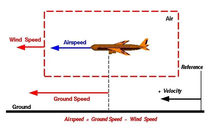
difference between ground speed and airspeed
True airspeed: is simply the speed at which an aircraft is moving relative to the air it is flying in. As such, it’s also the speed at which the air is flowing around the aircraft’s wings.
Ground speed: on the other hand, is the aircraft’s speed relative to the ground. One thing that should be noted here is that it’s horizontal rather than vertical speed – an aircraft climbing completely vertically would have a ground speed of zero.
In other words, while airspeed is what determines whether there is enough airflow around an aircraft to make it fly, ground speed is what determines how fast an aircraft will get to its destination.
3.
it not recommended to use aircraft engine power to move it on the ground at the Airport, due to the following reasons.
- noise: these engines make huge noise which causes noise pollution to environment around.
- engine wear: gravels on the ground and any other materials gets sucked up by the engine and destroys it and also if any bird that is flying on the runway might the engine as well
- fuel saving: 30mins of engine running is equal to 75kg of fuel burnt out,
So when airplanes are on the ground the process of moving them is called Airplane Towing.
4.
The process of pushing aircraft to the runway when it's ready to take off is called Taxiing.
before taxing there will be airplane towing as shown it also know as pushing the airplane from the parking to the taxi part.
Taxiing usually takes place only with one engine running due to the reasons mentioned in the above answer. the running engine pushes the airplane to the Lineup later both engines are turned on and will run on the runway and take off
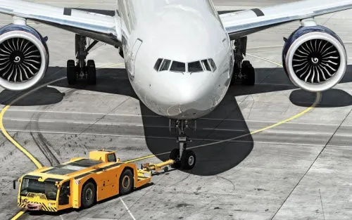
the future of pushback is electric here is how!!
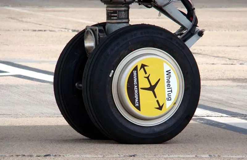
The future operation of aircraft will need to meet ever-demanding emission and efficiency targets and therefore, innovative solutions are required to support both new and in-service aircraft fleets. WheelTug is a company that has developed a pioneering concept to meet these challenges. They are developing a taxiing system consisting of a nose wheel mounted motor and drive, powered by the aircraft’s Auxiliary Power Unit. The ultimate goal of the system is to save time, engine life, and fuel use, resulting in reduced emissions and significant cost savings.
5.
Take Off Power in airplanes:
power required can be analyzed using the following plot:
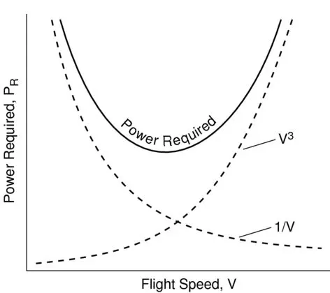
Power required:
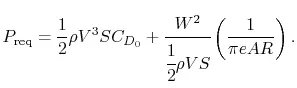
The total energy of an aircraft flying in the atmosphere can be calculated using equation
`E = ½ m v^2 + mgh`
This extra power needed to overcome the drag acting on the airplane and is calculated using
`P = ((dh)/dt) m g`
where (dh/dt) is the decent speed required to keep the plane's speed constant if the engines fail.
Take off:
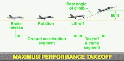
- while taking off the plane there are two speeds we need to have a look at V1, Vr, and V2.
- V1= is the speed that is needed to be achieved by the airplane before taking off.
- Vr= also know rotate speed is the speed at which the pilot begins to apply control inputs to make the aircraft nose pitch up, after which it leaves the ground. The easiest way to memorize the rotation speed is the point where the nose leaves the ground and vortexes are created at the wingtips which rotate behind the aircraft. Moreover, the point where the main gear leaves the ground is the point where the aircraft has reached the Vlof = lift-off speed.
- V2= is the speed at which the aircraft may safely be climbed with one engine inoperative. This speed is nicknamed a “take-off safety speed”; it is the speed an aircraft with one engine inoperative must be able to attain to leave the runway and get 35 feet off the ground at the end of the runway, maintaining a 200 ft/min climb thereafter. This is the lowest speed at which the aircraft complies with the handling criteria associated with a climb after take-off, followed by the failure of an engine.
Reduced power or derated takeoffs are normal and frequently used. The performance is carefully calculated before each takeoff, ensuring that the proper speeds, power settings, and flaps are used for the weight of the takeoff on the runway intended and at the proper temperature. When using this method during takeoff, it is always possible to increase to full power if the situation requires it. The captain always makes the final decision whether to use full thrust or derate.
Derates improve engine life and reliability. In addition to lowering operating costs, they decrease the likelihood of an engine failure.
Tire design:
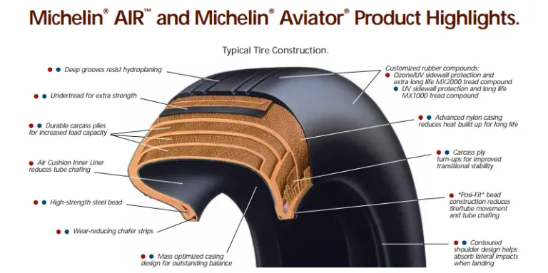
- 45 inches rubber
- inflated twice as much as truck tire and 6 times as much of car tire that is because higher the pressure greater the strength.
- filled with nitrogen because it is not combustible and can withstand pressure even in extreme weather conditions.
- can be loaded up to 38tons and 300mph speed rating
- 20 tires at 200psi of pressure and touched down more than 500 times before changing the tires
Why no grip on tires?
Hydroplaning
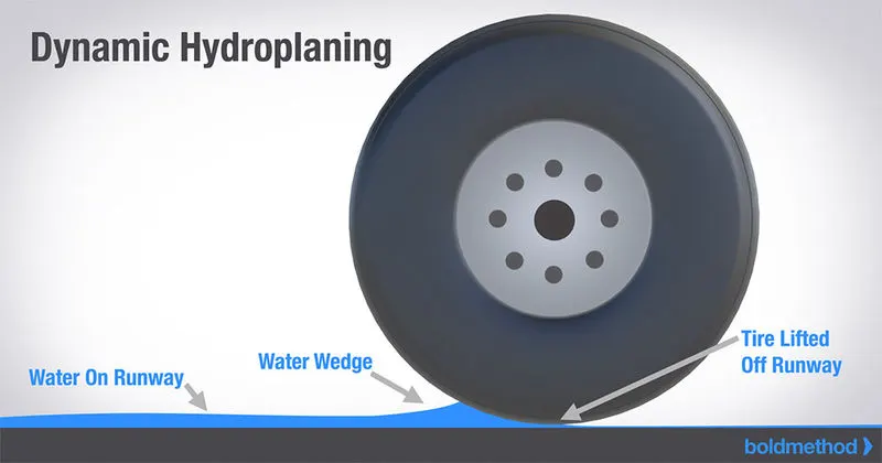
due to water present on the ground pushes the tire upwards and hence the tires are made in such way the water is splashed out our main priority is removing the water then the grip.
Rolling resistance:
Rolling resistance is calculated using the formula `R= μ(W - L)`
where R represents rolling resistance, μ represents the coefficient of resistance, W represents the weight of the aircraft and L represents lift.
On takeoff from a smooth, paved surface, rolling resistance is minimal. Aerodynamic drag is the key retarding force. R rolling resistance becomes the key retarding factor on a rough or difficult surface. Aerodynamic drag is still a retarding factor, but resistance to acceleration caused by the surface is of considerably more importance, particularly during the early stages of the takeoff roll
At higher levels of μ, the aircraft may not be able to develop sufficient thrust to even begin its takeoff roll.
Anti-skid system:
make sure that tires don't skid it will be constantly monitoring the tires when the tires rolling resistance is about to exceed the anti-skid system tries to release the brakes slowly making sure the tires don't skid these keeps repeating these thousands of time by releasing the brakes and applying them in a fraction of seconds
Brake Forces:
we require brakes in airplanes due to the following reasons:
- while taxiing if something comes up ahead we need to stop the plane, or even while turning the plane need to slow down a bit.
- as discussed above before taking off we need to reach the speed V1 where we will check out for any problems that are occurring in the controlling part or the engine part if any exist the take-off should be aborted and the plane as to slow down before it overruns the runway hence brakes are required.
- the braking energy required to stop the flight at V1 is equal to the kinetic energy of the flight at that moment.
i.e `KE=0.5*575,000kg*(87.4556m/s)^2`
=`2.2*10^9` = 2.2 GJoules.
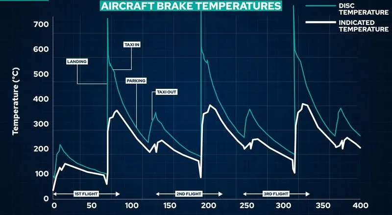
the braking is done using reverse thrust by using and discs brakes, a hydraulic piston which pushes the disc to increase the pressure, the material used is the steel disc or the carbon disc most the plates are fitted with steel brakes because they are manufacture and maintain carbon brakes are used to in lighter planes. because steel brakes weigh a lot and carbon brakes have much life span and also dissipates heat quicker and in steel discs due to lack of dissipation of heat the residual buildup of heat then brakes will saturation beyond which braking Detroit's.
Auto braking:
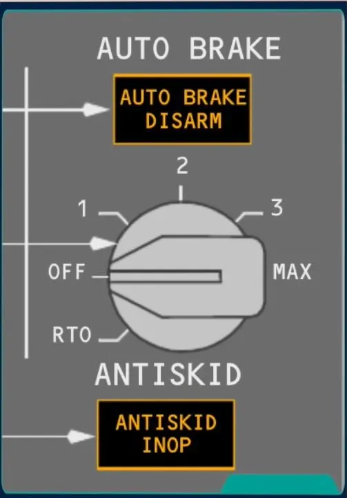
Auto-brake systems can be used on takeoff where they will provide maximum braking in the event of a rejected take-off and on the landing where they will provide a scheduled rate of deceleration (dependent upon the auto-brake level selected) using only a single brake application. These features combine to optimize the brake usage concerning the requirement and to minimize brake wear.
6.
Power required to pull/push an airplane by a towing vehicle.
assuming the average parameters of an airplane the following calculations have been done.
Mass:
- the total mass of the aircraft(including payload) = 575,000kg
- Mass of the push back: 1000kg
Rolling resistance(Frr):
- Coefficient of rolling resistance: `C_(rr)=0.002`
- Rolling resistance force is given by `F_(rr)=C_(rr)*m*g`
For the aircraft : `F_(rr)=(0.002)*(575,000)*(9.81)`
`F_(rr)=11.2815kN`
For the towing vehicle : `F_(rrt)=(0.002)*1000*(9.81)`
`F_(rrt)=19.62N`
Aerodynamic drag force:
- Drag coefficient (`C_d`)=0.025
- Air Density(`rho`)= 1.125`(kg)/m^3`
- Frontal area(A)= `150m^2`
- Velocity (v)= 14.5kmph
`F_(ar)=1/2*C_d*rho*A*v^2`
`F_(ar)=1/2*0.025*1.125*150*4^2`
= 33.75N
Hill climbing force:
`F_h=mgsintheta`
assumptions made so far are:
- The rolling resistance of towing vehicles can be neglected because it is less.
- As the vehicle and plane are moving at very low-speed aerodynamic resistance can be neglected.
- Runways are constructed flat so the gradient resistance/ hill climb force can be neglected.
Total resistance:
`F_t=11.2815kN`
Power required:
`P=F_t*v`
`P=11.2815*4`
P=45.26kW
The minimum power required by the tow vehicle is 45.26KW to push/pull an Aircraft at 4m/s.
Model to calculate the above results:
LINK OF THE BELOW MODEL(CLICK HERE)
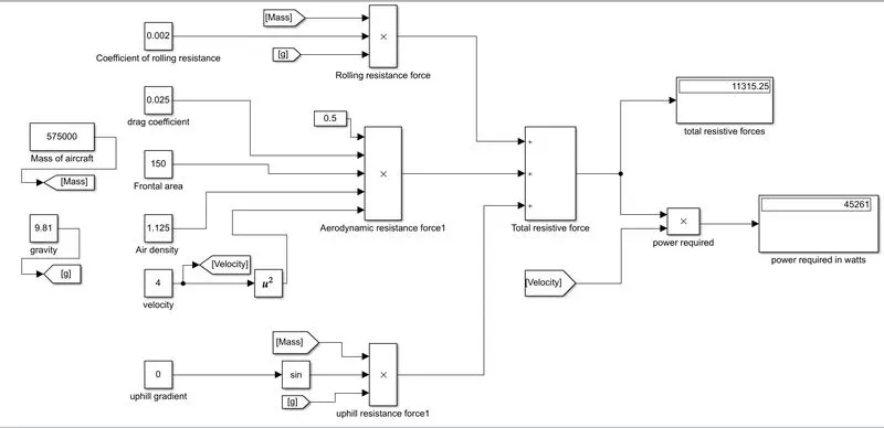
- Using the basic math operations blocks the above result is calculated.
7.
Tow tractor CHALLENGER 700
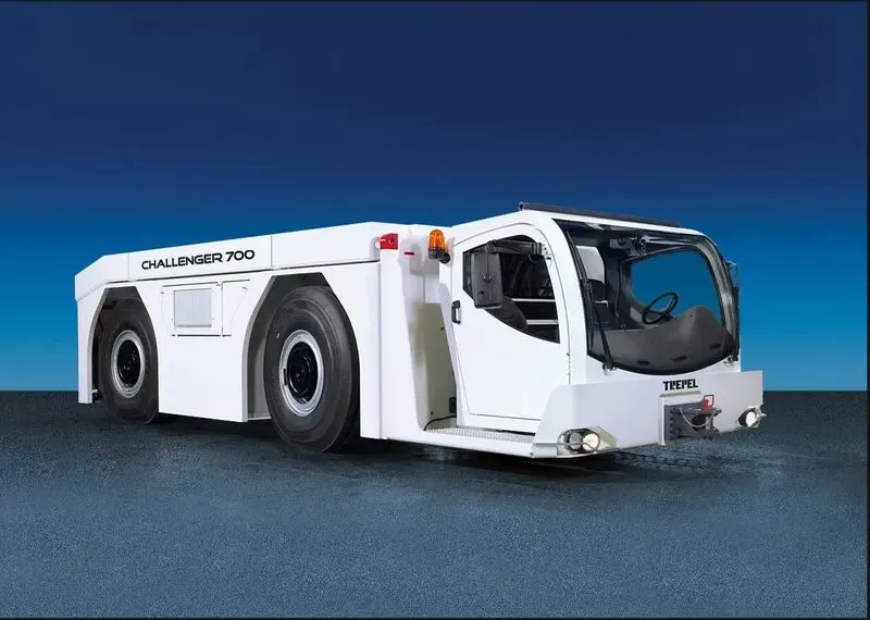
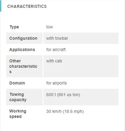
the above vehicle can tow up to a capacity of 661 ton and hence the airplane we are referring to can be carried as it is 575 ton
IE3 EFFICIENCY 3-PHASE INDUCTION MOTORS
TYPE: AESV3E, AESU3E.
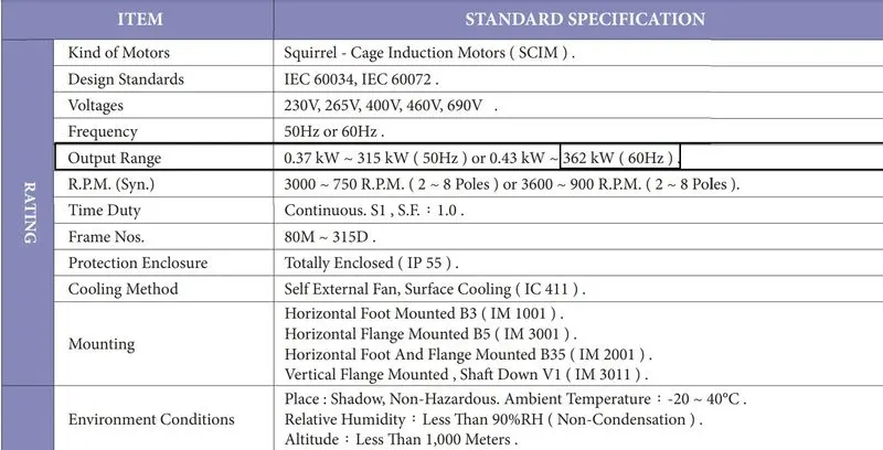
the above motor is considered for the drivetrain/powertrain.
Estimation of the duty cycle range to control the aircraft speed from zero to highest.
based on the previous calculation done the power required for towing an airplane is 45.26KW.
since the motor considered output power range is from 0.43KW to 362KW, we can choose the specifications as per our requirements.
Therefore, considering a 60KW as output power rating because we just require 45.26KW and considering 400V.
battery power is considered to be 550V
The duty cycle is given by output voltage/input voltage = `V_o/V_b`
here, Vo is motor required voltage and Vb is battery voltage.
D = `400/550=0.72`
as there will be losses due to the resistance.
the correction factor is considered to be 90%
as there is 10%loss, the voltage demanded by the motor should be 10% more than required
D= 0.72(1+0.1)=0.8
so the voltage demanded should be around 440V from the battery.
Table of assumed parameters
| Assumed parameters | values |
| Mass | 575000Kg |
| Co-efficient of rolling resistance(Crr) | 0.002 |
| Drag coefficient(Cd) | 0.025 |
| Air density | 1.25kg/m^3 |
| Velocity | 4m/s |
| Frontal Area | 150m^2 |
| uphill gradient | 0 |
| battery voltage | 550V |
| correction factor | 0.8 |
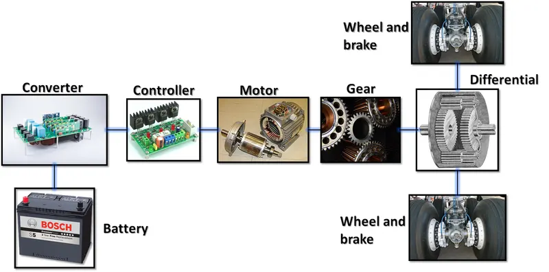
Block diagram of the powertrain.
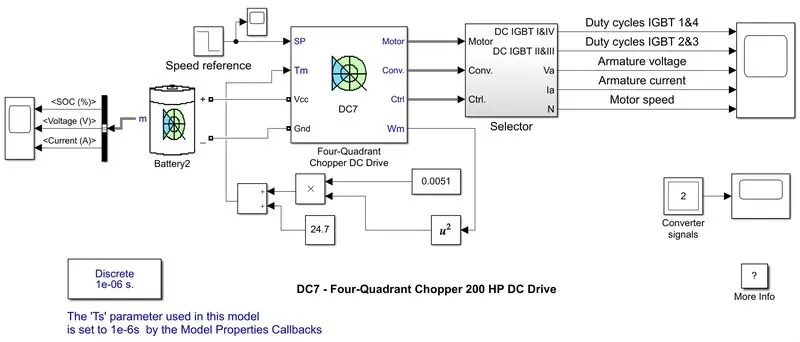
Simulink model :
using the DC7 block we are able to estimate the following results:
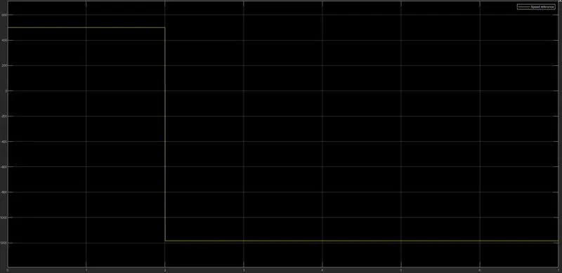
INPUT SIGNALS
Output signals:
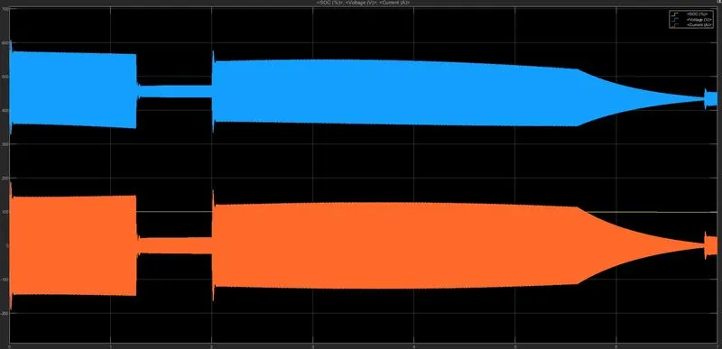
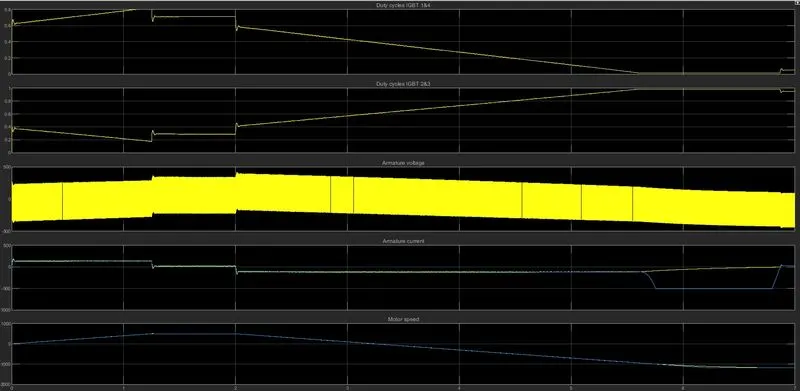
- Before starting the simulation, set the initial bus voltage to 515 V via the GUI block ('The Initial States Setting' button and 'Cbus' variable).
- Start the simulation. You can observe the motor armature voltage and current, the four IGBT pulses, and the motor speed on the scope. The current and speed references are also shown.
- The motor is coupled to a linear load, which means that the mechanical torque of the load is proportional to the speed.
- The speed reference is set at 500 rpm at t = 0 s. Observe that the motor speed follows the reference ramp accurately (+400 rpm/s) and reaches steady-state around t = 1.3 s.
- The armature current follows the current reference very well, with fast response time and small ripples. Notice that the current ripple frequency is 5 kHz.
- At t = 2 s, speed reference drops to -1184 rpm. The current reference decreases to reduce the electromagnetic torque and causes the motor to decelerate with the help of the load torque.
- At t = 2.2 s, the current reverses to produce a braking electromagnetic torque (dynamic braking mode). This causes the DC bus voltage to increase.
- At t = 3.25 s, the motor reaches 0 rpm and the load torque reverses and becomes negative. The negative current now produces an accelerating electromagnetic torque to allow the motor to follow the negative speed ramp (-400 rpm/s). At t = 6.3 s, the speed reaches -1184 rpm and stabilizes around its reference.
B.
LINKS:
CLICK HERE:DC7_MODEL
CLICK HERE: EXCEL SHEET