Week 6:- Clamp Unit & Pin-Clamp Unit Design Challenge
1.) Design 3 Different types of Swivel Clamp Unit with Different Riser, Blade, and Clamp Arm for the given Car Panel. Maintain the stroke as 100mm.
2.) Design a Pin-Clamp Unit for the given Car Panel.
Aim/Introduction/Objective: In this challenge we have to design three different types of swivel clamp unit with different riser,blade and clamp arm for the given car panel & design a pin-clamp unit for a given car panel with the optimum use of material and space constraint also considering panel thickness as 1mm for this unit.
Software Used: CATIA V5
Given parts/ Standard parts: Clevis cylinder & Car panel
Report and theory:
3-2-1 Principle achievement
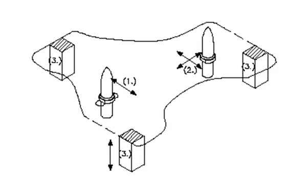
The 3-2-1 method is a work-holding principle where three pins are located on the 1st principle plane,i.e either XY.YZ,ZX and two pins are located on the 2nd plane which are perpendicular to the 1st palne and at last one pin on the plane which is mutually perpendicular to the 1st and 2nd palnes. The ultimate goal is to constrain the movement of the workpiece along all three axes.
3. Minimum
From the above figure, we can see three locator blocks positioned at the primary locating surface. These three locators restrict the axial upward and downward movement along the two radial movement both clockwise and anti clockwise are also restricted so a total of four radial movements is restricted to the two mutaually perpendicualr axes.
The three locators on the whole, have restricted six degrees of freedom
2. Round locating pin
The pin ddded in the location of the hole restricts the axial movements of two perpendicular axes. Thus restricting four degrees of freedom.
1. Round locating pin
The round locating pin is added to the slot in order to restrict the remaining radial movement in both both clockwise and anti-clockwise. Therefore restricts the remaining two degrees of freedom.
Thus, the 3-2-1 principle is used to restrict the 12 degrees of freedom of a part.
Clamp unit: Clamp unit is a unit designed to clamp/hold the the car panel with NC block/mylar/rest by using a pneumatic clamp cylinder and below are the different parts of a clamp unit in general. Usually clamp open position is 90 degree. Fingers are attach to clamp mylar. In clamp unit shim to one side is more enough because it will restrict traslation motion in upward and downword direction only. There is another type of clamp unit known as swivel type. There is pivot pin around which clamp arm rotate.
Factors should be considered while designing a clamp unit
- There should be adequate space between the cylinder and another part like riser, car panel because cylinder movers or swing while opening and closing.
- Pin clamp unit used where two panel or component are located for welding.
- Clamping make in such way that it clamp two car panels at once.
- All parts should snap and butt properly to each other.
- Make sure that parts of the clamping unit are 10 to 12mm away from the car panel so they do not damage car panel.
- Avoid any clash it will not arises issue at assembly.
Parts of clamp unit:
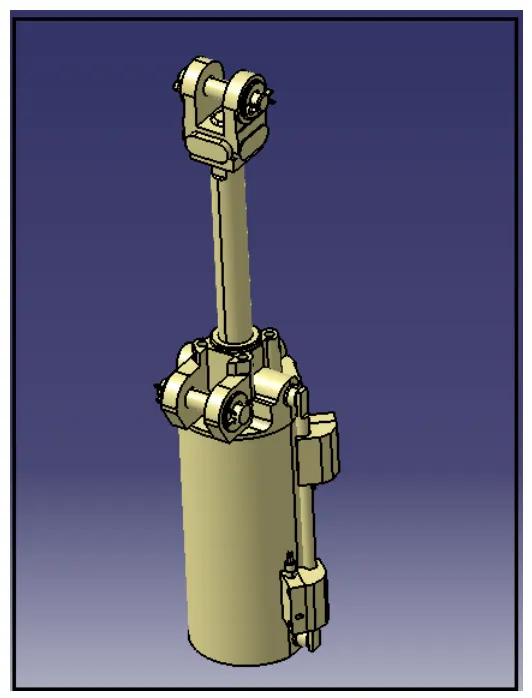
Clamp cylinder: Generally it is standar part.
Cylinder designation: In this unit we used clevis cylinder for clamping designation as CKG_1B_63_100Y
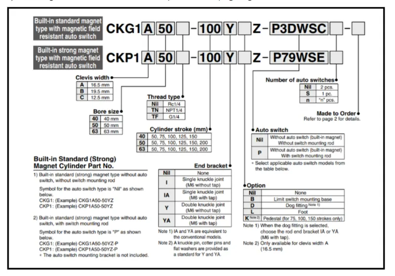
Nomenclature of cylinder as belows:
CKG1: Series of cylinder
B: Clevis width as 19.5mm
63: Bore size
100: Stroke of cylinder
Y: End bracket i.e. double knuckle joint (M6 without tap)
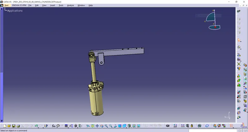
Arm: The long length part attached to the swivel cylinder and perpendicular to the cylinder axis. Clamp mylar is attached to it which moves with arm. It has two plates 8mm thickness welded and helps in rotating of clamp arm about pivot point of blade. The distance between cylinder rod hole and pivoting hole should be 50mm. This is necessary because cylinder stroke 100 mm must be achieved when it is 90 degree open position and clamp aem mounting hole must be in line with cylinder rod.
Mylar/NC block/Finger: Finger is a movable part which is used to hold the car part from the top against backup and they are usually mounted on the clamp arm. These are used to hold the panel. They are globally called as mylar. Top side mylar is called clamping mylar and bottom side is called resting mylar. Every clamping mylar should have resting mylar. It is jaw type. It prevent panel from deforming while welding.
- Clamp and rest mylar has the same size. it has standard size of 20mm X 20mm.
- Clamp and rest mylar have two dowel holes of diameter 6mm and one M8 tapping hole. Clamp mylar have the same mounting hole pattern as like clamp arm. The minimum centre distance holes should be 15mm.
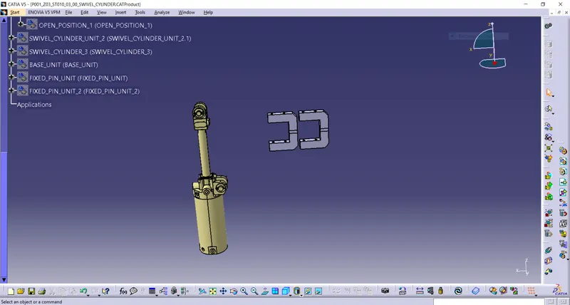
L-block: L- shaped blocks are used to mount the finger to clamp arm also allow to adjust for locator pin in two directions.
Stopper: The function of stopper is to restrict motion of clamp arm. It avoids clamp arm to rotate beyond limit. It has two parts male and female. The part attached to the arm is called as female part and part attached to the blade is called male part.
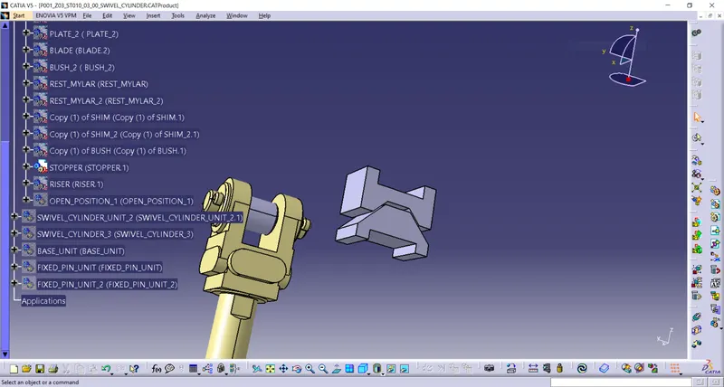
Shim/Spacer : They allow the finger to be moved to the correct xyz location and allow the customer to make adjustments to improve the quality the their product. In fixture, we provide tolerance to each part mostly manufactured. Those tolerances tend to stack up and reflect together. In order to avoid that we use shims so we can easily adjust after assembly so whatever stack up there we will rectify it through shims. Shims come in thickness of 0.1, 0.2, 0.5mm etc.
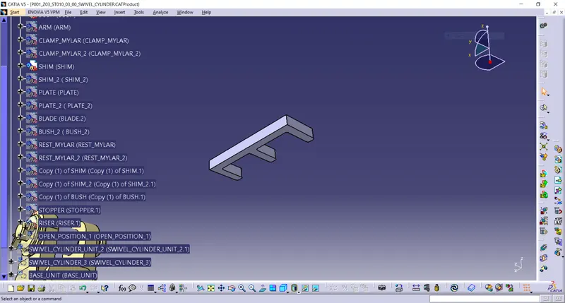
Blade: Parts onto which all the other elements are attached to. Blade is designed accordance with the position of all other parts.
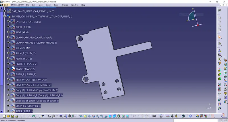
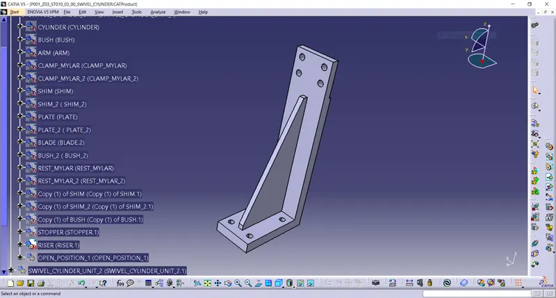
Riser: L- shaped ot T shaped tall block which regularly patterened holes to attach the above mentioned parts in modular way blade space . Riser is either a make part part or standard part. These are basically manufactured parts are used to give height to assembly.
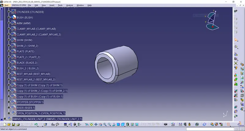
Bushes: Bush is friction type bearing. It is lubricated with grease, oil. It permits relative motion between two mating parts. It is made of hard material also its ID and OD are precisely machined or grinded. It is press fitted and after worn out is is replaced with new one instead of replacing other part which save cost. Mostly phosphor bronze or gun metal material used for making bush. In this unit three bhuses are used of same internal 12mm and 18mm external diameter but different length.
Hardwares: Add all hardware screws, dowels and washer as per the size. Ensure all these hardwares are easy to dismantel.
STRUCTURING A DESIGN TREE
- Structuring a design tree implies process where all the assemblies and parts are named in specific manner. Different customer have different set of standard like how to structure a design tree? so they will be give standard template based on that design tree structure, which helps us to identify specific part of assembly. It speciifes the project number, station number, unit number, part number of each component so that it is easy to identify the parts.
- It is an importnant process which helps us to identify a specific part or assembly as to which project, tool or unit, it belong to.
- This helps us to avoid error during design study, manufacturing, assembly, inspection etc.
- If parts or assemblies are not named properly or the design tree is not structured properly, it will create confuse to understand and create major possiblities of making an error.
- Naming of a fixture , a unit or a part gives the information as to which project or zone or assembly they do belong.
- It can help us to identify quantity of items of same type or different types that are being used in assembly for e.g. bolt. It actually tells you how many bolts are particularly required in that assembly or unit.
- For e.g. as P001_Z01_ST006_01_01. P001 stands for project no. 1, Z01 stands for zone no. 1, ST006 stands for station no.6, 01 stand for unit no., 01 stands for part no.
BELOW ARE THE SOME IMAGES OF CLAMP UNIT WITH AND WITHOUT OPEN POSITION
1ST CLAMP UNIT WITHOUT OPEN POSITION
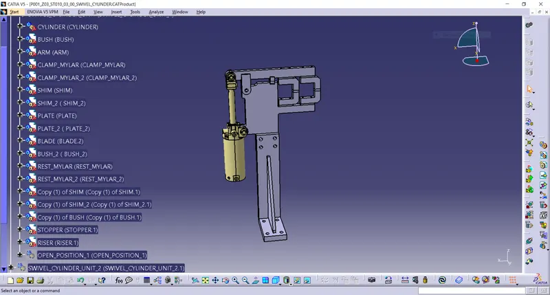
1ST CLAMP UNIT WITH OPEN POSITION
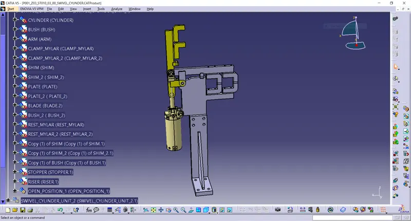
2ND CLAMP UNIT WITHOUT OPEN POSITION
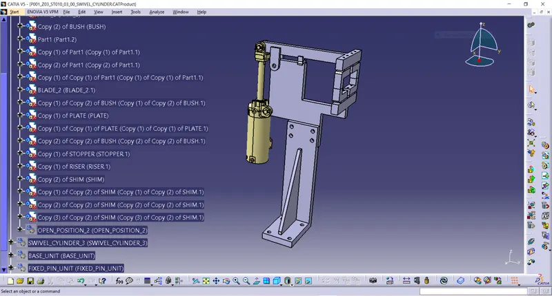
2ND CLAMP UNIT WITH OPEN POSITION
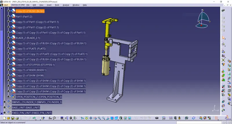
3RD CLAMP UNIT WITHOUT OPEN POSITION
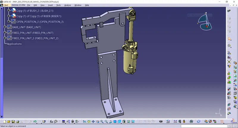
3RD CLAMP UNIT WITH OPEN POSITION
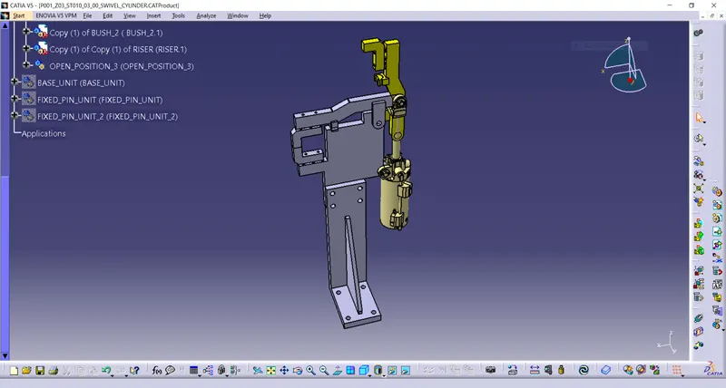
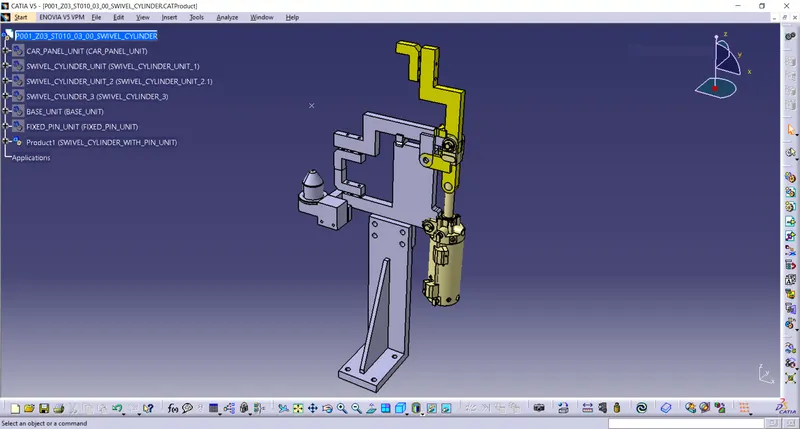
SWIVEL CLAMP UNIT WITH A PIN UNIT COMBINED
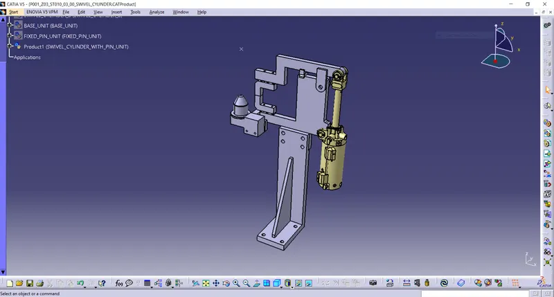
SWIVEL CLAMP UNIT WITH A PIN UNIT COMBINED (OPEN POSITION)
ALL THREE CLAMP UNIT ASSEMBLY HOLDING THE CAR PANEL
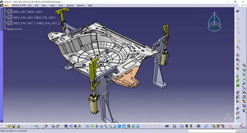
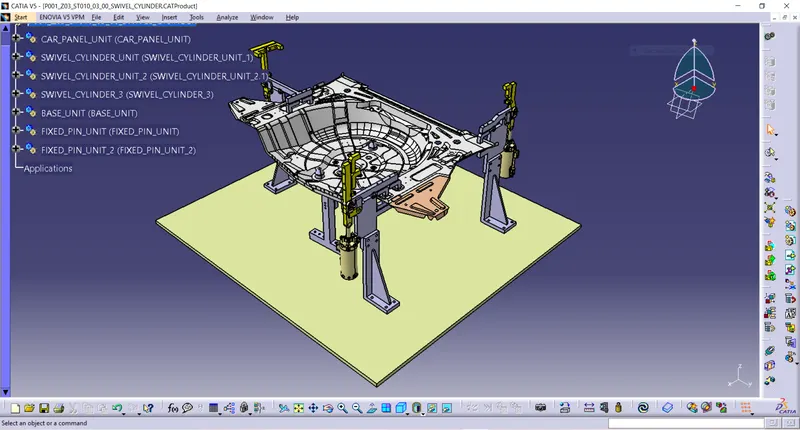
ALL THREE CLAMP UNIT ASSEMBLY WITH CAR PANEL AND BASE UNIT
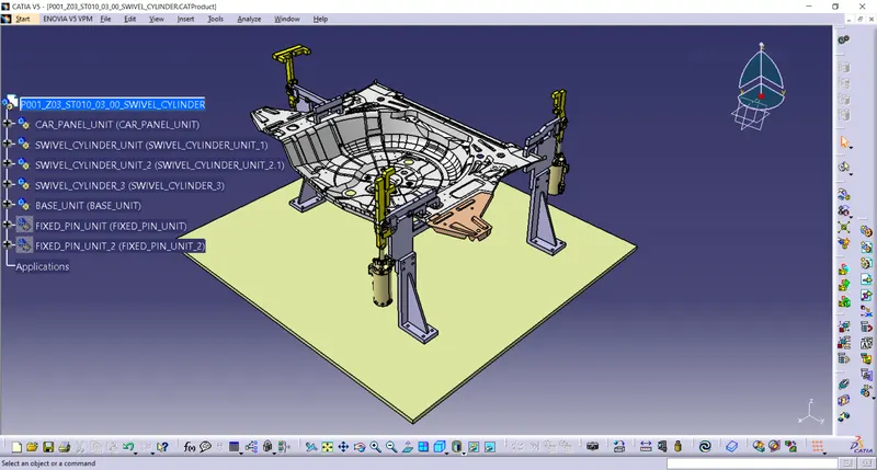
ALL THREE CLAMP UNIT AND PIN UNIT ASSEMBLY WITHOUT CAR PANEL
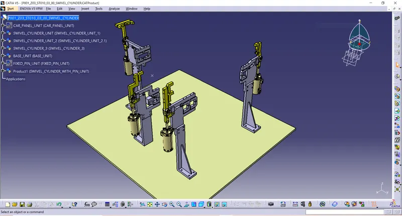
ALL THREE CLAMP UNIT ASSEMBLY WITH CAR PANEL ,PIN AND BASE UNIT
CONCLUSION
Thus i have designed 3 different types of clevis clamp unit with different riser,blade and clamp arm for a given car panel and unit which consist of both clamp unit and a pin unit combined.