Assignment 1-2D Meshing Challenge
OBJECTIVE:
- To perform the geometry cleanup operation on the given files.
- To extract the midsurface of the model.
- To clean the midsurface of the model.
- To create 2D mesh with target length 5mm having minimum length 3.5mm having minimum length 3.5mm and maximum length 7mm.
- To assign proper thinkness to the mesh by creating a generic property.
Part-1:
- We will first import the model in Hypermesh using the Import model browser option present in Tool Bar.
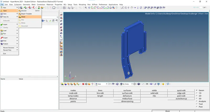
- Ater importing the model, we can see that there are some free edges and missing surfaces in the model.
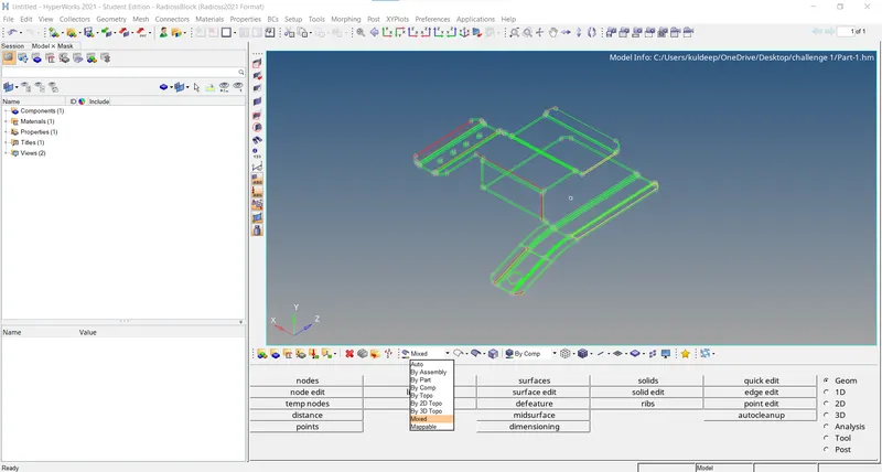
- So we will need to perform the geometry clean-up on the model.
- Geometry cleanup is peformed on the model to obtain refine geometry which output better results in midsurface and therefore the meshing of the component.
- To perform the geometry cleanup we will navigate to the quick edit panel by either pressing the F11 shortcut key or through the Geom page.
- In the quick edit panel, we will use the toggle edge option to toggle most of the free edge red lines to the shared edge green line.
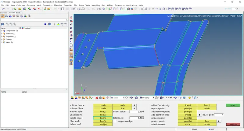
- We will also use filler surf to fill any missing surface and replace the node option to replace and retain points to complete the geometry.
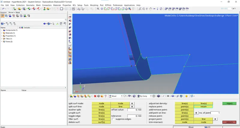
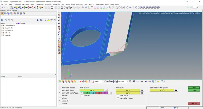
- Delete the unwanted surfaces from the model (Yellow lines).
Delete/F2 - surface - select the surface from model - click delete entity
Geom - surface edit - trim with surf/plane - select the surface - trim
Delete/F2 - surface - select the surface - delete entity
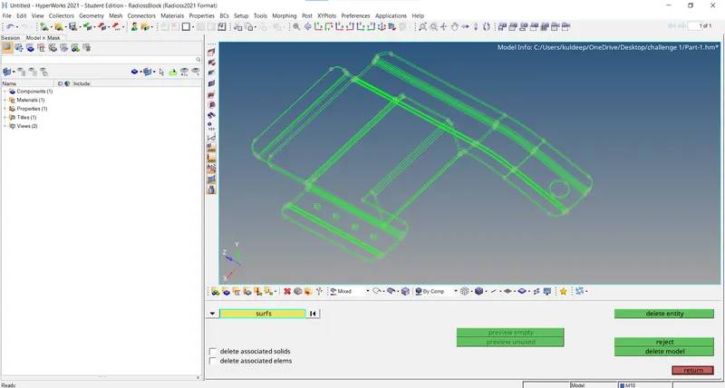
- After Geo cleaning the model will look like as shown below.
Midsurfce:
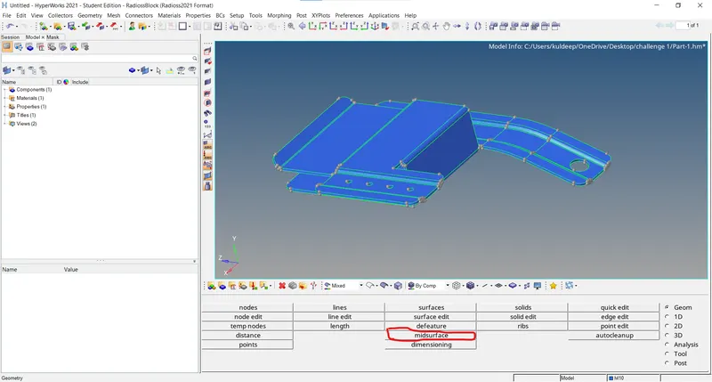
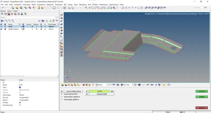
- To obtain the mid surface of the model, we will navigate to a mid surface panel on the Geom page.
- Under extraction option, we will select offset+planes+sweeps, then we will select all the surfaces of the model in the auto extraction subpanel, and then we will click on the extract command.
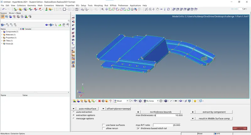
- Hypermesh will perform auto mid surface and we will obtain the mid surface of the model.
Fillet removing:
Geom - Defeatue - surf fillets & edge fillets & pin holes - enter minimum value - select the model - find - remove.
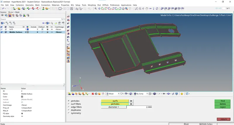
- The fillet which are less than the minimum element length are removed using the defeature option.
- To defeature the fellet, the defeature option in the Geo page, and in that use the surface fillet option and select the fillet region that needs to remove.
- Similarly, all the fillet regions which are failing for the minimum element length are removed.
Mesh:
- In general, 2D meshing is ferformed for the objects having a thickness of less than 6 mm.
- To perform 2D meshing on the model, we will navigate to the Automesh panel either by pressing the F12 shortcut keyor through the 2D page.
- Geom - distance - two nodes - select the nodes from model - nodes between
- Tools - rotate - select 4 nodes from model - select the nodes of ements to move - give angle value (5) - rotate
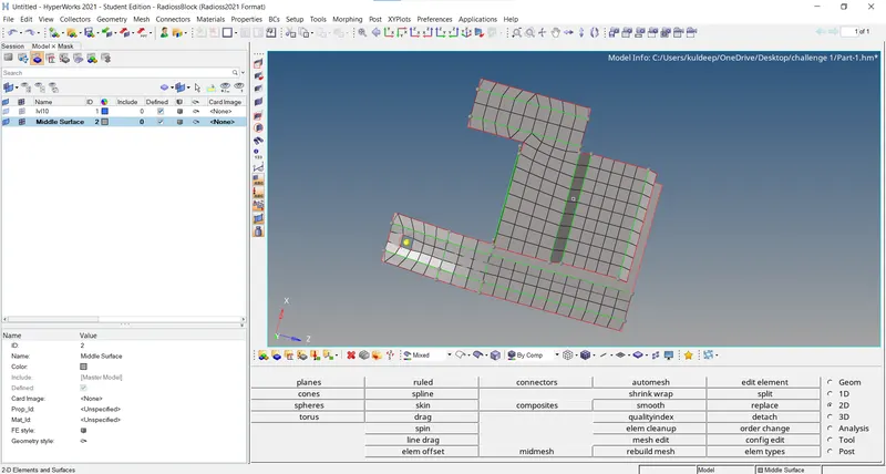
- To mesh, we will select the surface one by one and create the mesh with target element size as 5 mm and mesh type as mixed.
- We will make sure that the holes are captured with an even number of nodes and there are fewer trias generated in the mesh.
- After completing the meshing of the model, we will check for quality criteria by pressing the F10 shortcut key or check element panel on the tool page.
- Here we will check for minimum length as 3.5 mm and maximum length as 7 mm criteria.
- If any elemnts are failing the quality criteria, we will optimize them by using cleanup tools and various commands such as combine, split, align, element optimize, smooth, project, replace node etc.
Assign Thickness Value:
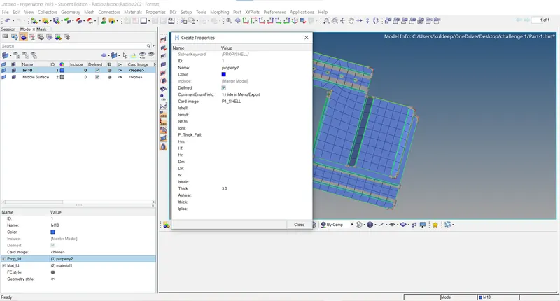
- To assign thickness to the elements as per parent geometry thickness, we will create a new property.
- The thickness of the parent model is 0.91 and so enter the 0.91 as thickness in Property Entity Editor window.
- Now we will assign this property to the Middle surface component in the Model Browser by right-clicking on the it and choosing the assign option.
- this will assign the thickness to the meshed elements.
- To view the thickness mesh, we will choose the 2D Detailed Element Representation in Toolbar.
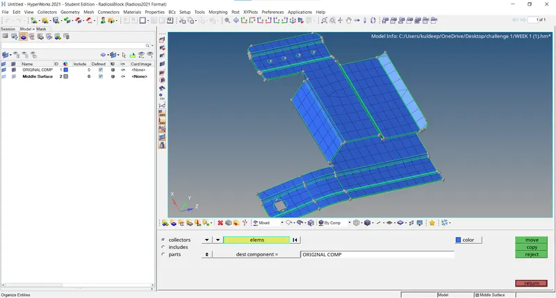
- Tools - organize - destination(original) - element (displayed) - Move
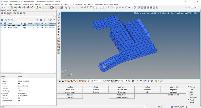
Final Model:
Part-2:
Import model:
- We will first import the model in hypermesh using the import model browser option present in the tool bar.
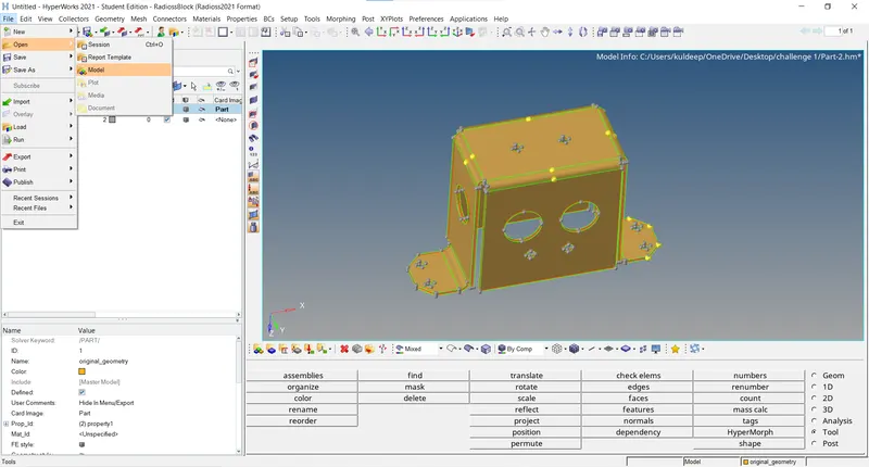
- After importing model,we can see that there are some free edges and missing suffaces in the model.
- So we will need to perform the geometry clean-up on the model.
- Geometry cleanup is performed on the model to obtain refine geometry which outputs better results in mid-surface and therefore the meshing of the component.
- To perform the geometry cleanup we will navigate to the quick edit panel by either pressing the F11 shortcut key or through the geom page.
- In the quick edit panel,we will use toggle edge option to toggle most of the free edges red lines to the shared edge green line.
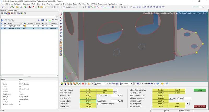
- We will also use filler surf to fill any missing surface and replace the node option to replace and retain points to complete the geometry.
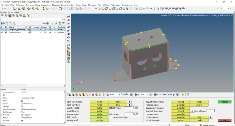
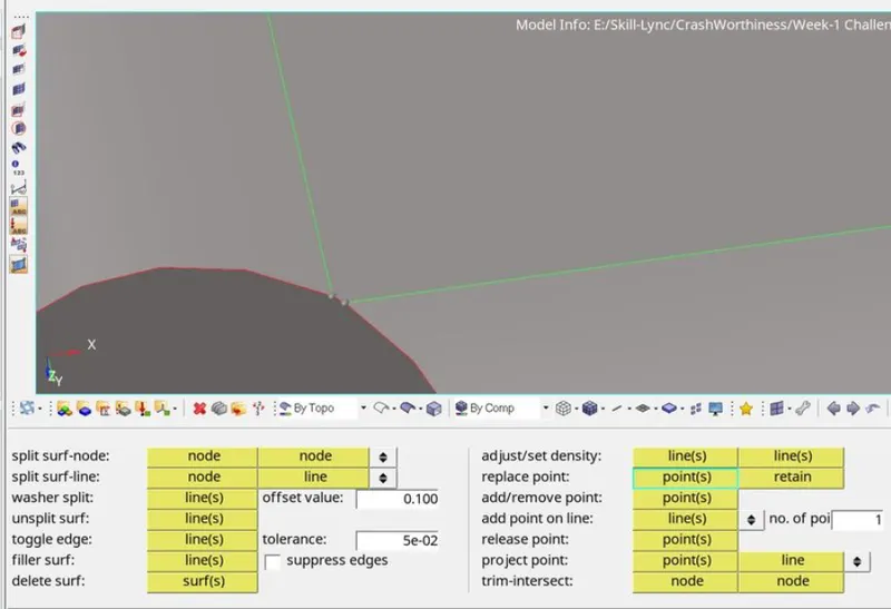
- After geo cleaning the model will look like as shown below.
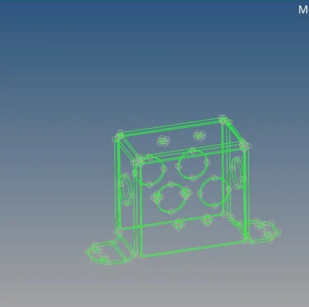
Midsurfce:
- we will select skin offset , then we will select all the surfaces of the model in the auto extraction subpanel, and then we will click on the extract command.
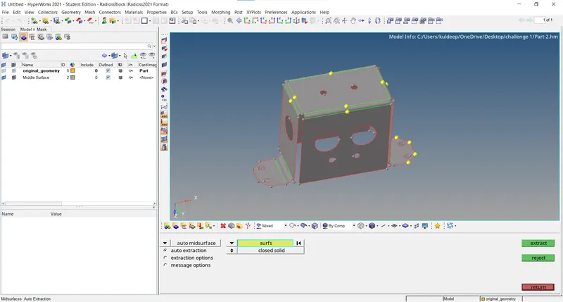
- To obtain mid surface of the model,we will nagivate to the mid surface panel on the geom page.
- Under extraction option,we will select skin offset,then we will select all the surfaces of the model in the auto extraction subpanel and then we will click on the extract command.
- Hypermesh will perform auto mid surface and will obtain the mid surface of the model.

Geo cleanup for the proper mesh flow:
The points which are close to each other are connected to a single line in order to achieve proper mesh.
Mesh:
- In general, 2D meshing is performed for objects having a thickness of less than 6 mm.
- To perform 2D meshing on the model, we will navigate to the Automesh panel either by pressing the F12 shortcut key or through the 2D page.
- To mesh, we will select the surface one by one and create the mesh with target elemnt size as 5 mm and mesh type as mixed.
- One half has only meshed and it is reflected on the other side using reflect option/Position.
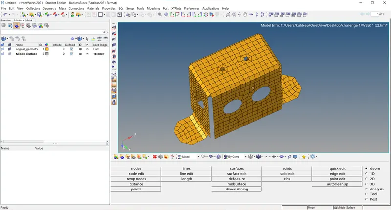
Equivalence:
- After reflecting the elements on the other side, using the edges option in the tool page view.
- Using the equivalence option, equivalence the nodes which are having small gaps.
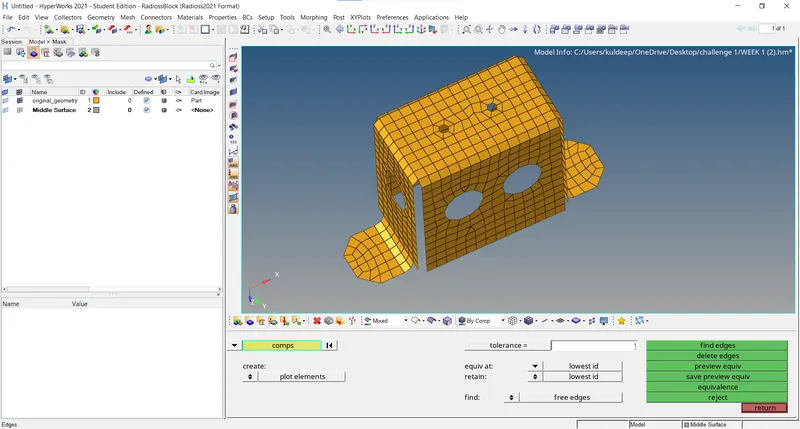
Mesh:
- Similarly, the other side also meshed one side and reflected another side or by position.
Edge finding:
- After meshing all the surface, the free edge is found using the edges option in the tool page view.
- In case if any free edge is found within the surface, the points are pasted together to avoid any free edge.
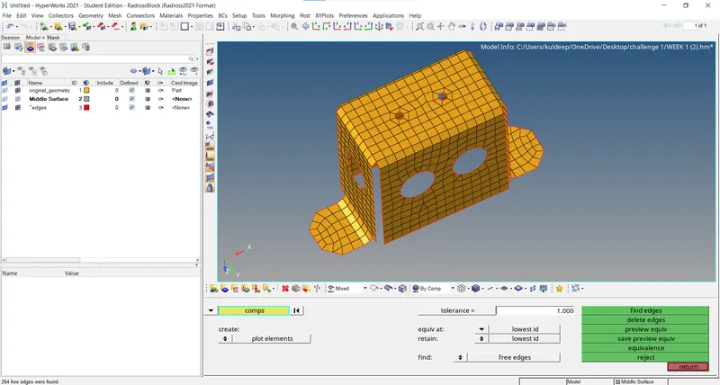
Assign Thickness:
- To assign thickness to the elements as per the parent geometry thickness, we will create a new property.
- The thickness of the parent model is 2 and so enter the 2 as thickness in Property Entity Editor window.
- Now we will assign this property to the Middle surface component in the Model Browers by right-clicking on in and choosing the assign option.
- This will assign the thickness to the meshed elements.
- To view the thickness mesh, we will choose the 2D Detailed Element Representation in Toolbar.
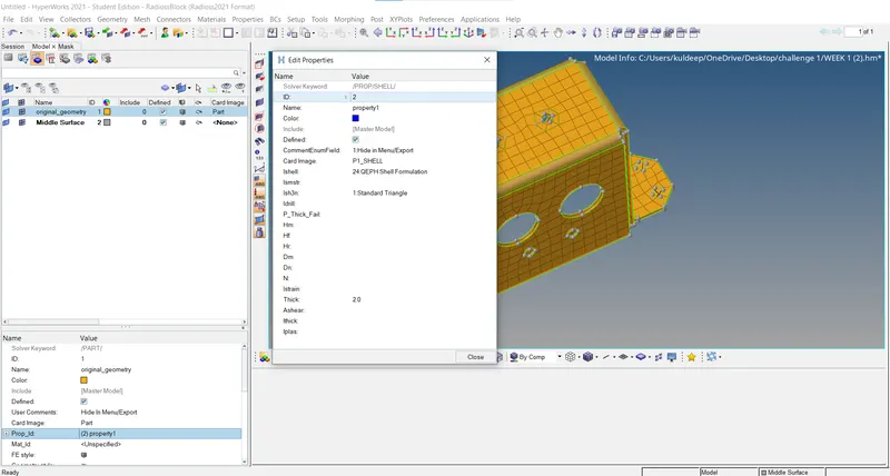
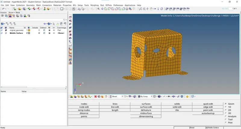
Final Model:
Part-3:
- We will first import the model in Hypermesh using the Import model browser option present in Tool Bar.
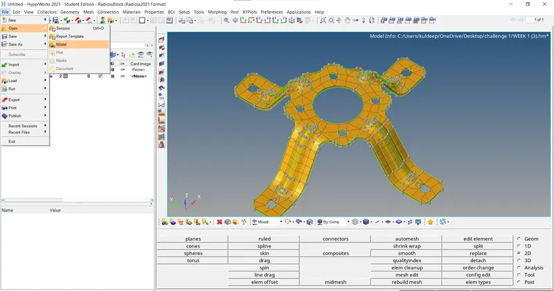
- Ater importing the model, we can't see that there are some free edges and missing surfaces in the model.
- Geometry cleanup is peformed on the model to obtain refine geometry which output better results in midsurface and therefore the meshing of the component.
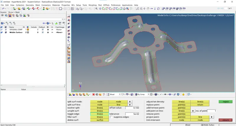
- To perform the geometry cleanup we will navigate to the quick edit panel by either pressing the F11 shortcut key or through the Geom page.
- In the quick edit panel, we will use the toggle edge option to toggle most of the free edge red lines to the shared edge green line.
Midline creation:
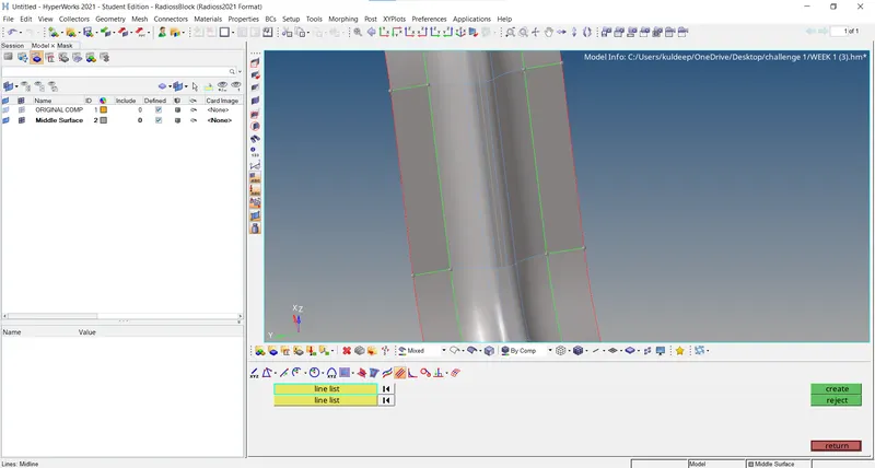
- In order to capture the surface much better, the surface which is failing for the minimum element length is removed by taking midline between.
- using the midline, the surface is trimmed by using the surface edit option.
- After the surface is trimmed the other two line are toggled.
Mesh:
- In general, 2D meshing is performed for objects having a thickness of less than 6 mm.
- To perform 2D meshing on the model, we will navigate to the Automesh panel either by pressing the F12 shortcut key or through the 2D page.
- To mesh, we will select the surface one by one and create the mesh with target elemnt size as 5 mm and mesh type as mixed.
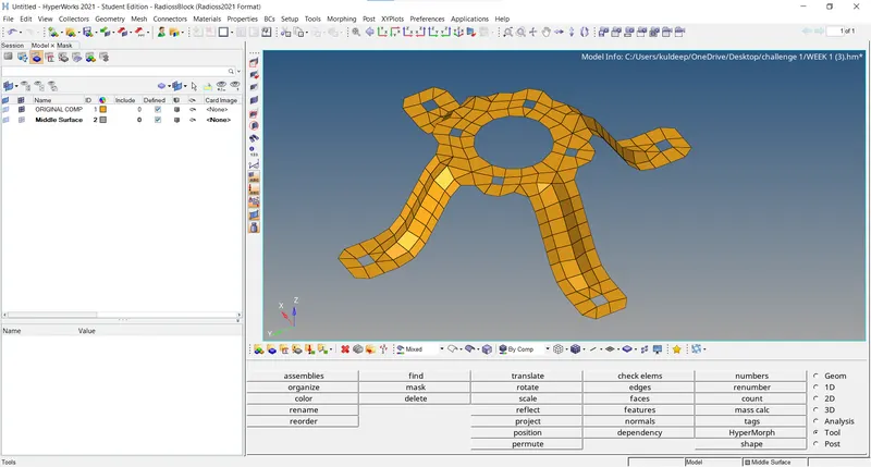
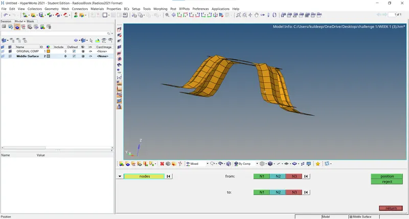
- One face has only meshed and it is reflected on the other side using Position option.
Assign Thickness:
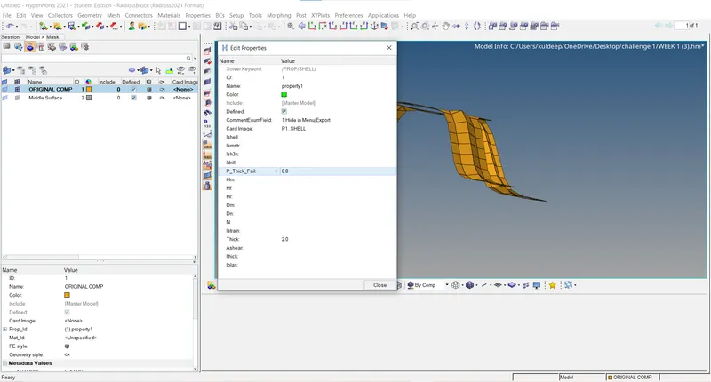
- To assign thickness to the elements as per the parent geometry thickness, we will create a new property.
- The thickness of the parent model is 2 and so enter the 2 as thickness in Property Entity Editor window.
- Now we will assign this property to the Middle surface component in the Model Browers by right-clicking on in and choosing the assign option.
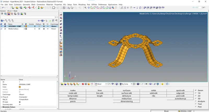
- This will assign the thickness to the meshed elements.
- To view the thickness mesh, we will choose the 2D Detailed Element Representation in Toolbar.
Final Model:
CONCLUSION:
- Extracted the mid surface and performed the geometry clean-up on the given components.
- Generated a 2D mesh on the given components by following the element quality criteria.
- Finally,assign the thickness for the given components.