Week 9:- 2D Detailing Challenge
1) What are the Drawing templates?
- Drawing templates are the files of frames and titles block which convey the design information that are used to generate 2D drawing from 3D part.
- Neat and detailed drawing templates convey more information from designer to manufacturer, so we can avoid misunderstanding and make a very effective parts,which saves time and money.
- Drawing templates are change as per the company standards.
- Drawing templates are provided by the customer at starting of the project,if not then we should finalize at starting of project.
- Drawing templates are basically the drawing standards as per customer's specifications
- Drawing templates are format that are used for detailing of different parts or units of the fixture.
- A drawing template file is drawing file that has been svaed with a .dwt file extension, and it specifies the styles,settings and layouts in a drawing including title blocks.
- Drawing template also gives information about the angle of projection to be used,views to be considered,scaling of the drawing as per the part or unit.
- Separate template is prepared for each sheet size like A1,A2,A3,A4 & so on..
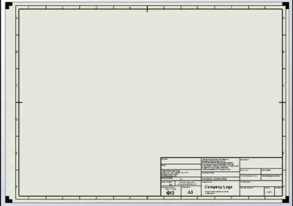
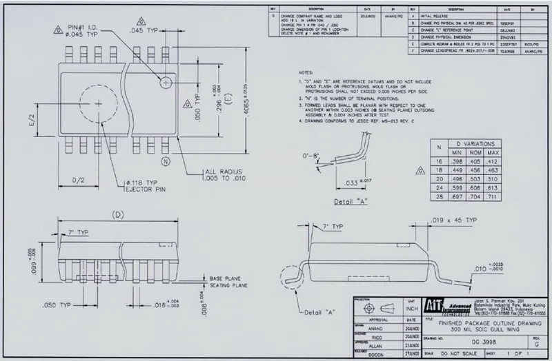
A Drawing template has n number of information such as:
- Company name
- Project name
- Sheet number
- Angle of projection
- Rivision number/letter(if its revision drawing)
- Signature or name of drawn by,responsible engineer and approved by
- Parts details
- Quantity
- Additional notes( surface finish,heat treatment,material details etc.)
- Scale,date,unit of measurement
*Note: Above points can vary as per company standard.
2) What do you understand by Angle of projection?
- The angle at which an observer draw an object to covert it from 3D to 2D plane such as real object image to a plane paper is known as angle of projection.
- Angle of projection are basically the view formats for orthogonal views of assemblies or parts.
- Orthographic projections: It is technical drawing in which different views of an object are projected on different reference planes observing perpendicular to respective reference plane.
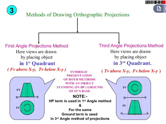
- There are two types of projection method majorly used in industry.First and third angle of projection are majorly used in automotive standards.
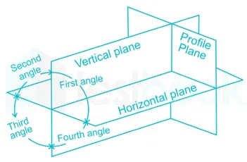
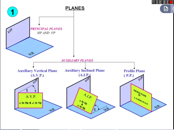
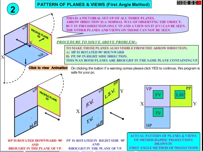
- Different reference planes are horizontal plane(HP),Vertical plane(VP), Side or profile plane.
- Different views are front view(FV),Top view(TV) and Side view(SV).
- Understanding the angles of projection helps us to derive the actual image of 2D drawing.
- It is also very important for various manufacturing process for machine shop operators.
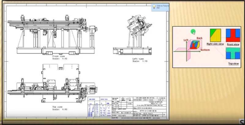
- Symbol used for first and third angle of projection are as below
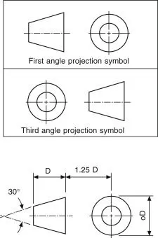
- Front view is projected on vertical plane
- Top view is projected on horizontal plane
- Side view projected on profile plane
3) What is the First angle & Third angle projection? and why can't we use the 2nd and 4th angle of projection?
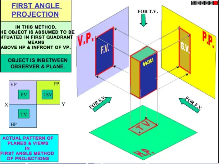
First angle of projection
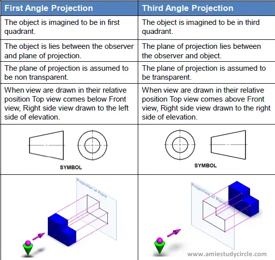
- In this, the object is assumed to be positioned in the first quadrant and is shown in figure.The object is assumed to be in between the projection plane and the observer.The views are obtained by projecting the images on the respective planes.
- In this type of projection,the object is imagined to be in the first quadrant because the obsrver normally looks from the right sideof the quadrant to obtain the front view,the objects will come in between the observer and the observer and the plane of projection therefore,in this case the object is imagined to be transparent and the projectors are imagined to be extended from various points of the object to meet the projection plane.When these meeting points are joined in order on the plane they form an image,thus in the first angle projection,any view is so placed that it represnts the side of the object away from it.
Third angle of projection
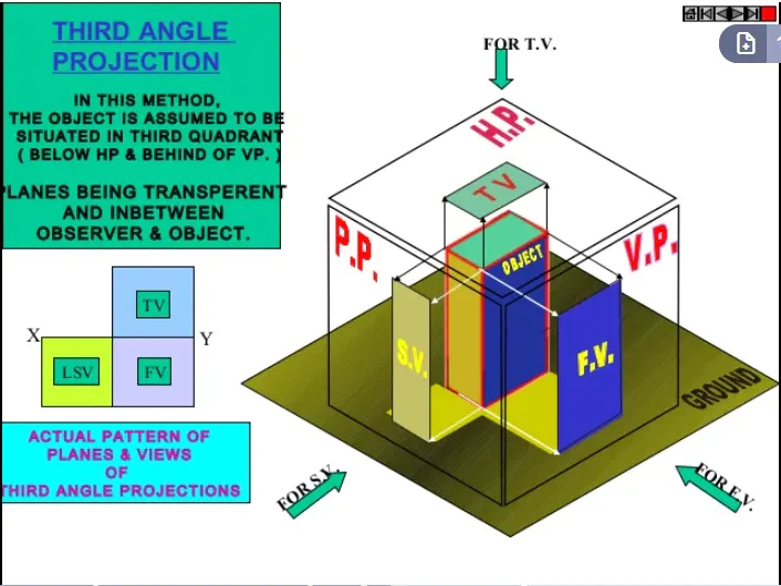
- Here the object is asseumed to be in the third quadrant, i.e, the object behind the vertical plane and below the horizontal plane.In this projection technique,placing the object in the third quadrant puts the projection planes between the viewers and the object and is shown in figure.
- In this type of projection,the object is imagined to be in the third quadrant. Again,as the observer is normally supposed to look from the right side of the quadrant to obtain the front view,in this method,the projection plane comes in between the observer and the object therefore,the plane of projection is assumed to be transparent.The intersection of this plane with projectors from all the points of the object would from an image on the transparent plane.
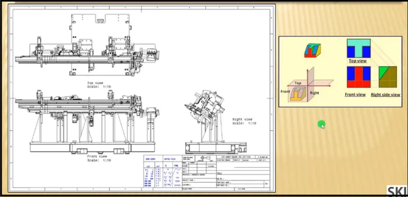
The basic difference between first and third angle of projection are as belows:
2nd and 4th angle of projection is not used?
Second and fourth angle of projection systems are not used to draw engineering drawing because of the limitation of overlapping projection views.
How orthographic projection system works?
Lets's consider a point A and B in the 1st and 3rd quadrant respectively.As per rule of orthographic projection, to bring drawing views from three dimentional to two dimentional planes. Horizontal plane (HP) is rotated in the clockwise direction.
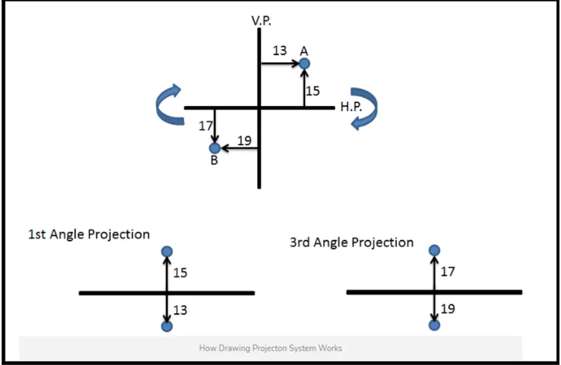
As shown in above figure,point A in the first quadrant lies in between the observer and projection plane therefore front view of A point will be in the vertical plan and the top view will be on the horizontal plane similarly point B is in 3rd quadrant can be projected on the orizontal and vertical plane.
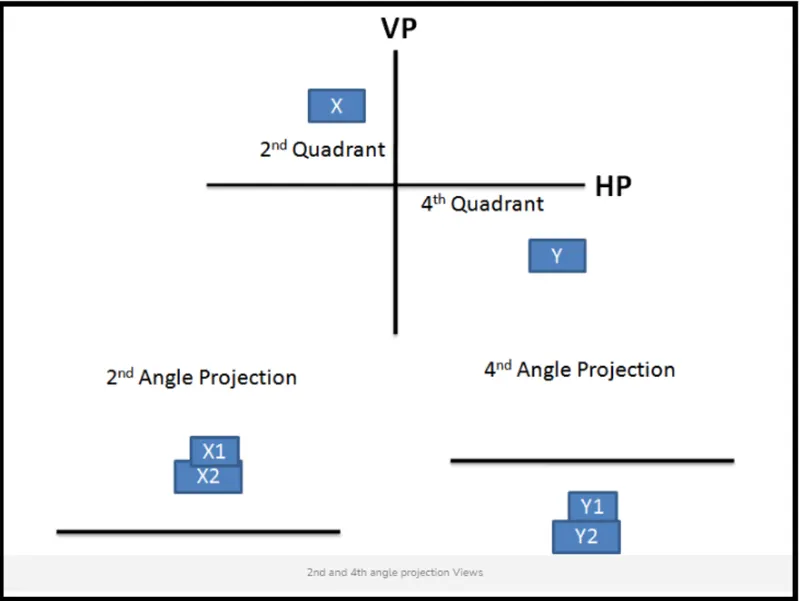
To understand why the 2nd and 4th angle orthographic projection system are not used to draw engineering drawings. We will repeat the above experiment of creating engineering drawing views in the second and fourth quadrant.
Let's consider rectangular parts X and Y are placed in 2nd and 4th quadrant respectively.
In the second quadrant, the vertical plane lies in between object X and observer therefore the front view of the object X will lie on vertical plane whereas top view will lie on horizontal plane. As per rule of projection when the horizontal plane is rotated 90 degree in clockwise direction,top and front view will overlap. Overlapping projection views create confusion in the drawing therefore the 2nd angle of projection system is not used to draw engineering drawings. Similarly when the object is placed in the 4th quadrant both top and front view overlap therefore fourth angle projection is also not used.
4) What is GD&T? What are the benefits of GD&T?
Geometric dimentioning and tolerancing (GD&T) is a design approach and manufacturing mechanism that helps engineers and designer communicate how to bring a part to life.When documented correctly using GD&T, its is possible to build a part that exactly matches its on-paper plans.
The drawing is the controlling document that ensures the vendor is creating precisely what the customer's design requires. Machinist and quality engineers will use GD&T,print dimensions,and drawing notes to develop a manufacturing process and inspection methodology that will construct high-precision components matching the designer's original vision.Proper print detailing will also help with measurement corelation to aid in the communication between customer and vendor.
GD&T uses a symbolic language to indicate how significantly part features can deviate from the geometries listed in the design model.This language contains all relevant details involved in fabrication,including dimention,tolereances,definitions,rules and symbols that communicate a component's functional requirements.These all currently follow ASME Y14.5M-2009(Previously ASME Y14.5-1994).
Engineers and designers look to GD&T to design critical aspects of a part's features,including a specific features's location,from.profile and orientation.It is common practice to use the profile designation tied to the datum structure that is related back to the solid CAD model.This allows manufacturing to use a best fit protocol.
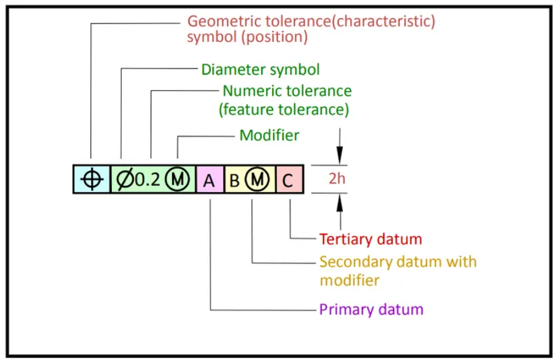
A feature control frame (the backbone of GD&T) modifies a parts's geometry.
FIVE MAJOR ADVANTAGES
GD&T, a vital part of complex machining,offers a number of major advantages:
- Saving Money- GD&T enhances design accuracy by allowing for appropriate tolerances that maximize production.For many projects,the process provides extra or bonus tolerenaces,further increasing cost effectiveness.
- Ensuring Dimentional and Tolerances Requirement- By explicity stating all design requirement a thorough GD&T process guarantees and accurate fulfilment of all dimentional and tolerenaces specification.
- Assisting Digital Design Methods- clear,concise GD&T data is readily adaptable to digitl design programs,including nearly universally used 2D and 3D CAD files.
- Offering Uniformity and Convenience- As a single,consistent language,GD&T reduces guesswork and interpretation while ensuring conistant geometries across design and manufacturing.
- Providing Accurate Communication- Today's intricate design demand the most accurate and reliable communication.GD&T enables designer,manufacturer and inspectors to communicate clearly with one other,saving time and making the process more efficient.
5) Explain all the symbols used in GD&T?
There are total of fourteen GD&T characteristics and the symbols that represent them are shown below:
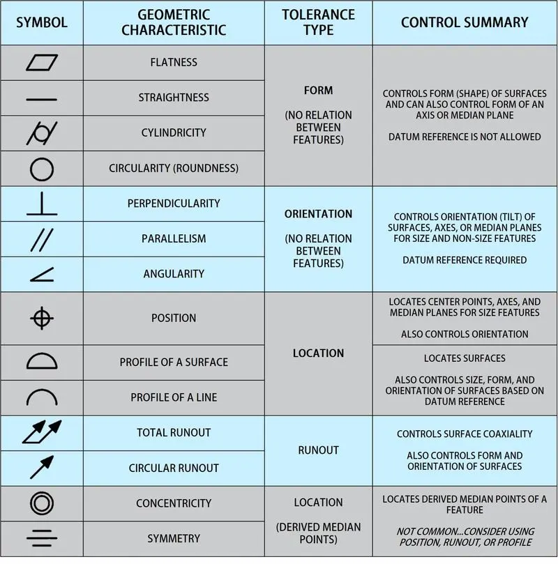
FORM TOLERANCES: Controls the shape of features and are often used as refinement of size.
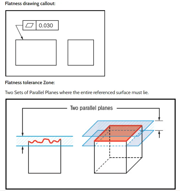
- Flatness: GD&T flatness is a common symbol that references how flat a surface is regardless of any other datum's or features.It comes in useful if a feature is to be defined on a drawing that needs to be uniformly flat without tightening anu other dimensions on the drawing.The flatness tolerances references two parallel planes(parallel to the surface that is called out on) that define a zone where the entire reference surface must lie.
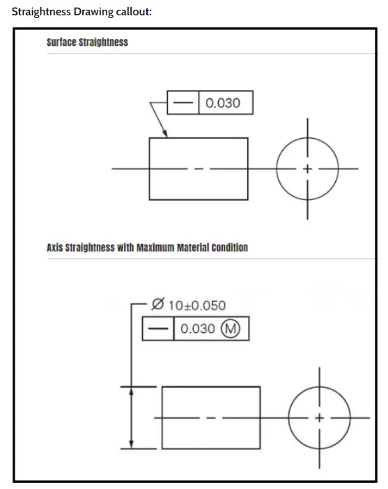
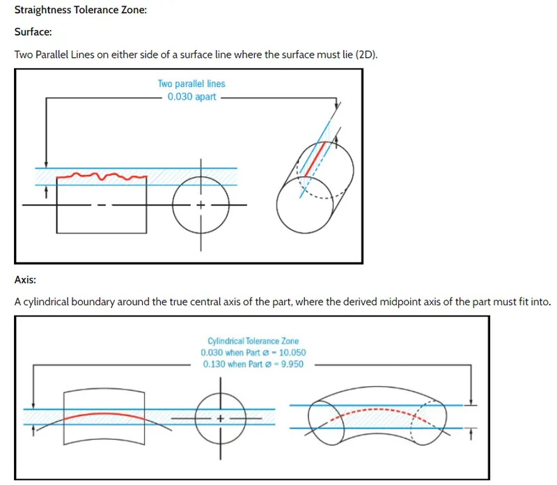
- Straightness: Straightness actually has two very different functions in GD&T depending on how it is called out.In its normal form or surface straightness, is a tolerance that controls the form of a line somewhere on the surface or the feature.Axis straightness is a tolerance that controls how much curve is allowed in the parts's axis.This is usually called out with an inclined call to maximum material condition. Both callouts are very different from each other.
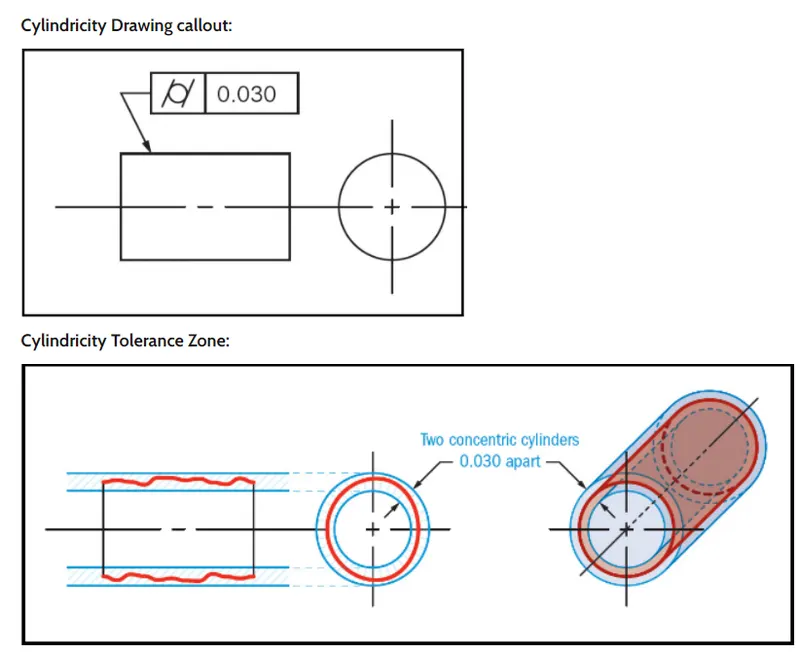
- Cylindricity: The cylindricity symbol is used to describe how close an object conforms to a true cylinder.cylindricity is a 3-dimentional tolerance that controls the overall form of a cylindrical feature to ensure that it is round enough and straight enough along its axis. Cylindricity is independent of any datum feature the tolerance need to be less than the diameter dimentional tolerance of the part. Cylindricity essentially forms a perfect cylindrical boundary around the object that entire 3-dimentional part must lie in.
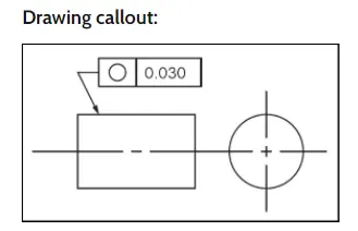
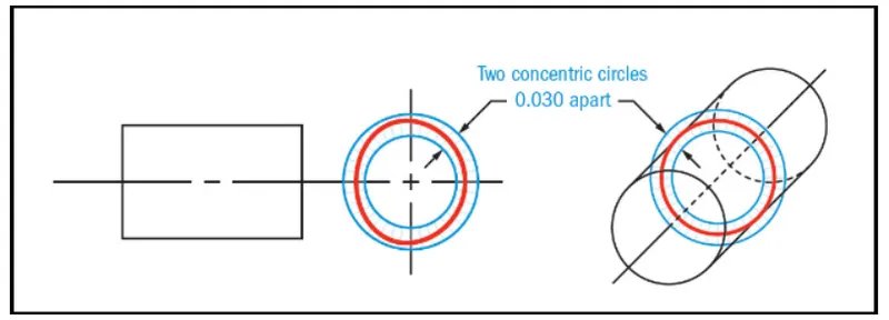
- Cirularity: The circularity symbol is used to describe how close an object should be to a true circle.Sometimes called roundness,circularity is a 2-dimentional tolerenace that controls the overall form of a circle ensuring its is not too oblong,square or out of round.Roundness is independent of any datum feature and only is always less than the diameter dimentonal tolerance of the part.Circularity essentially makes a cross-section of a cylindrical or round feature and determines if the circle formed in that cross-section is round.
Tolerance zone: Two concentric circles ,one inner and one outer,in which all the points within the circular surface must fall into.The tolerance zone lies on a plane that is perpendicular to the central axis of the circular feature.
ORIENTATION TOLERANCES: Controls the tilt of features and always associated with basic angle dimentions often used as a refinement to location applied to surface,orientation tolerences also control form.
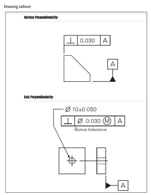
- Perpendicularity: Perpendicularity in GD&T can mean two very different things depending on which reference is called out.The normal form or surface perpendicularity is a tolerance that controls perpendicularity between two 90 degrees surfaces or feaures. Surface perpendicularity is controlled with two parallel planes acting as its tolerance zone.Axis perpendicularity is a tolerance that controls how perpendicular a specific axis needs to be to a datum.Axis perpendicularity is controlled by a cylinder around a theoretical perfectly parallel axis.Pay close attention if a hole or pin is referenced since axis perpendicularity is commonly called out on these features.
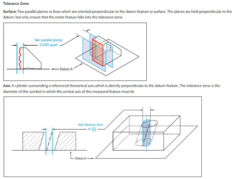
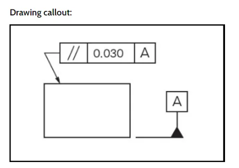
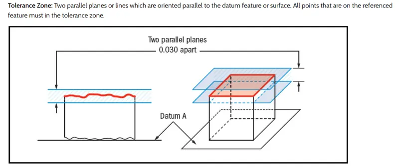
- Parallelism: parallelism actually has two different function in GD&T depending which reference feature is called out.The normal form or surface parallelism is a tolerance that controls parallelism between two surfaces or features. The surface form is controlled similar to flatness with two parallel planes acting as its tolerenace zone.Axis parallelism is a tolerrance that controls how parallel a specific parts central axis needs to be to a datum plane or axis.The axis form is controlled by a cylinder around a theoretical perfectly parallel axis. Parallelism is most commonly called out as surface parallelism.However be sure to pay attention if it is referencing a central axis because it is different.
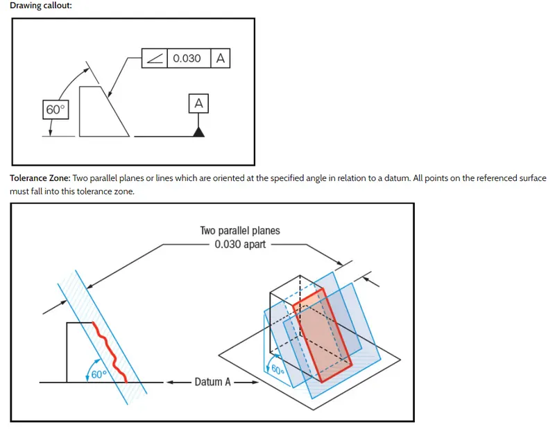
- Angularity: Angularity is the symbol that describe the specific orientation of one feature to another at a referenced angle.It can reference a 2D line referenced to another 2D element,but more commonly it relates the orientation of one surface plane relative to another datum plane in a 3-Dimentional tolerance zone.The tolerance does not directly control the angle variation and should not be confused with angular dimension tolerance such as +- 5 degeree. In fact,the angle,for now becomes a basic dimension,since it is controlled by your geometric tolerance.The tolerance indirectly controls the angle by controlling where the surface can lie based on the datum.
LOCATION TOLERANCES: Controls location and are always associated with basic linear dimentions.Position locates and orients the median plane or axis of features of size. Profile locates feature surfaces. Profile is the most powerful characteristic of all and also controls orientation and form.
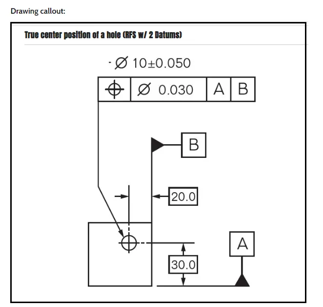
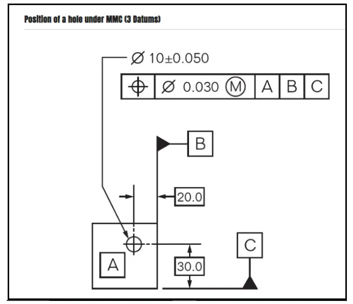
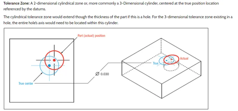
- Position: True position is actually just referred to as position in the ASME standard. Many people refer to the symbol as true position,although this would be slightly incorrect.The position tolereance is the GD&T symbol and tolerance of location.The true position is the GD&T position tolerance is how far features location can vary from its true position.
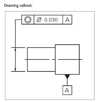
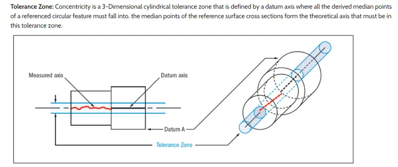
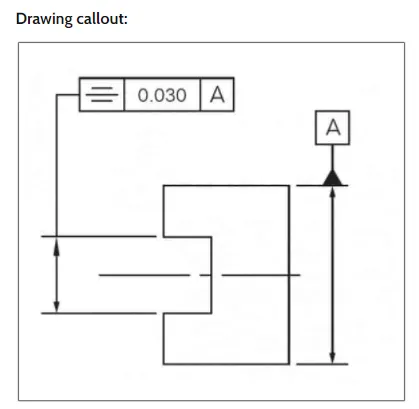
- Concentricity: Concentricity,sometimes called coaxially,is a tolerance that controls the central axis of the referenced feature,to a datum axis.The axes for the datum and referenced feature are derived from the median points of the part or feature.Concentricity is a very complex feature because it relies on measurements from a derived axis as opposed to tangible surface or feature.
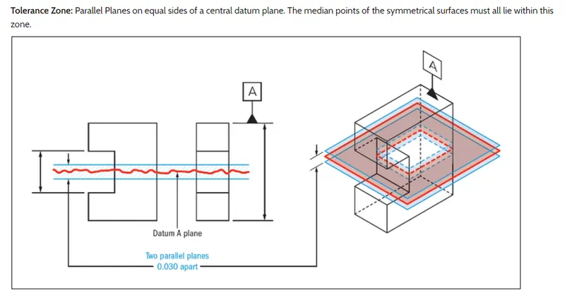
- Symmetry: GD&T symmetry is a 3-dimentional tolerance that is used to ensure that two features on a part are uniform across a datum plane.An established true central plane is established from the datum and for the symmetry to be in tolerenace,the median distance between every point on the two surface features needs to fall near that central plane.Each set of points on the reference features would have a midpoint that is right between the two.If you take all the midpoints of the entire surface,this must lie within the tolerance zone to be in specification.Symmetry is not very common GD&T callout since it has very limited functional uses( centering location is done with position) and the verification and measurement of symmetry can be difficult.
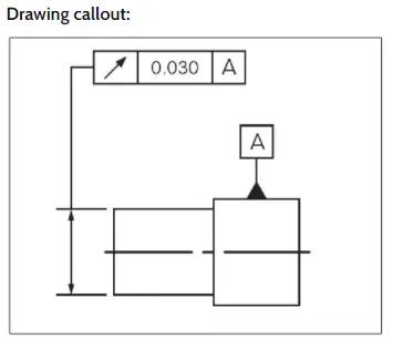
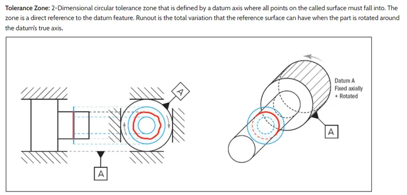
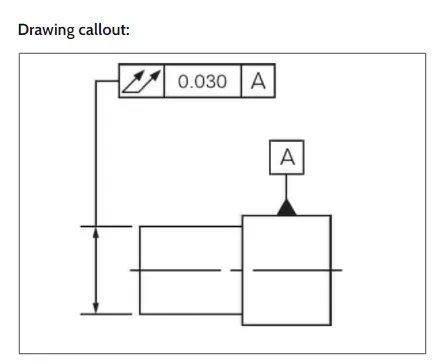
RUNOUT: Runout is how much one given reference feature or feature vary with respect to another datumwhen the part is rotated 360 degrees around the datum axis.It is essentially control a circular features and how much variation it has with the rotational axis. Runout can be called out on any feature that is rotated about the axis.It is essentially how much "wobble" occur in the one part features when referenced another.
- Circular runout
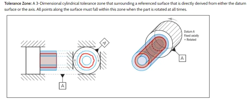
- Total runout: Total runout is how much one entire feature or surface varies with respect to a datum when the part is rotataed 360 degereee around the datum axis.Total run out controls both the amount of variation in the surface as the part is rotated,but the amount of variation in the axial dimention both radial variation and axial variation are measured and held within the tolerance.Total runout is usually cllled on a part that is rotated about an axis where the entire surface is critical to be spec.
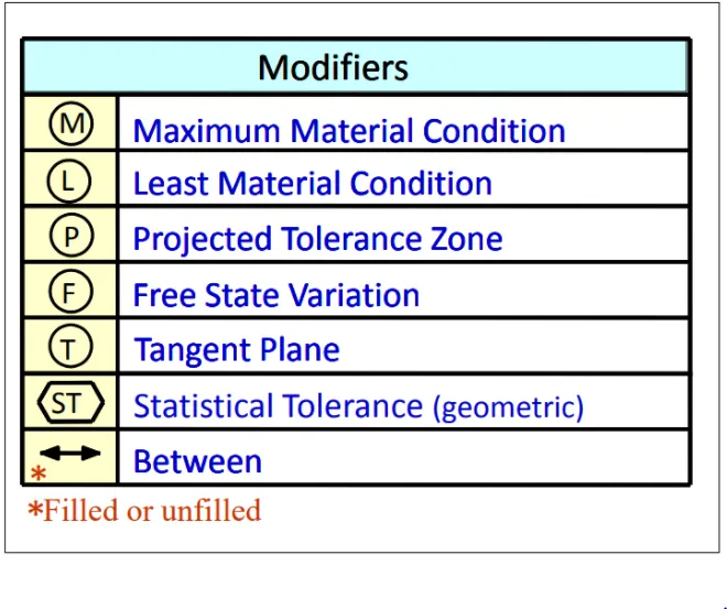
Some other symbols used GD&T
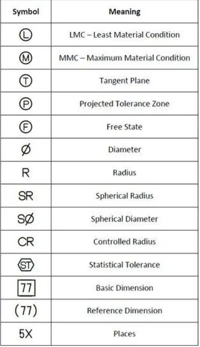
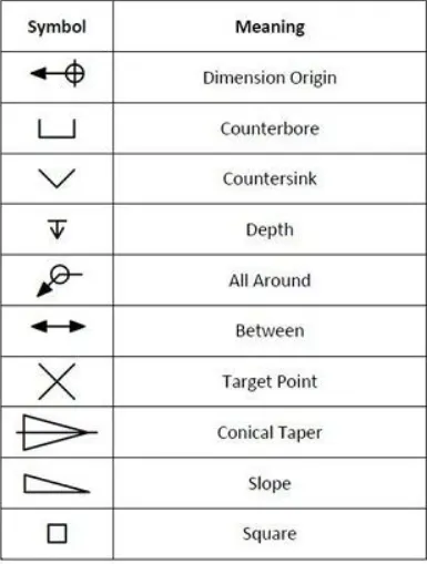
Leat material condition(LMC): The condition where the feature contains the least material within the stated limits of size (eg.small pin or large hole).
Maximum material condition(MMC): The condition where the feature contains maximum material with in the stated limits of size (eg.large pin or small hole).
Projected tolerance zone: The projected tolerance zone applies to a feature's protrusion. In most cases the zone to which geometric tolerances applied is limited to the range of features specified in the drawing. In contrast to this,indications using the projected tolerance zone can specify a virtual zone for the specificed features mating part.
Basic dimension: Basic dimensions are theoretically exact numerical values used to define form,size,orientation or location of part or features.Basic dimensions are usually shown on a drawing enclosed in a box,but they can be invoked by referencing a standard or by a note on the drawing.
Free state: Adds the free state modifier, to indicate that the geometric tolerances applied in the unrestrained condition.This modifier is only applicable for not rigid parts for which there is note that indicates that tolerances are specified for the restrained state.