Week 8:- 3D Finishing Challenge 2
Aim/Introduction:
Perform 3D finish for all units of assembly design.Create rough locators for assembly.
Theory:
3D Finish
3D finish is a process where the design is being completely finish and to be ready for the final simulation and 2D detailing.This is the stage in the process where the position of rough locators is identified
Following points are taken into consideration while finishing the design
- Hole concentricity and hole size: The parts which are to be fastened together should have concentric clearance holes and threaded holes with corrsponding sizes.
- Machining Areas: The surfaces which are to be machined should be represented with proper coloring
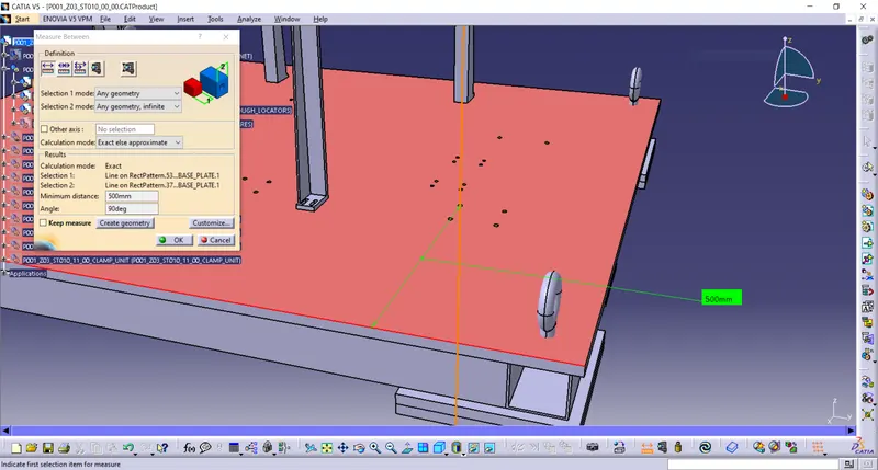
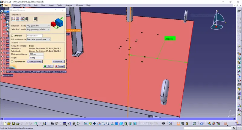
- Norminality: The coordinates of the units should not be in demimal. All the units should be edited with respect to base in order to get norminal dimension. Pin units are exception for this as the locationg hole is input from the company and should not be edited unnecessarily.
- Hole coloring standard: The fastening holes and dowel holes should be given standard colors. Dowel hole is navy blue,clearnace hole is aqua and threaded hole in yellow in color.
- Pneumatic Lay-outing: Pneumatic channeling should be provided on the base plate for all the connection which would connect pneumatic cylinders and solenoid valave box.
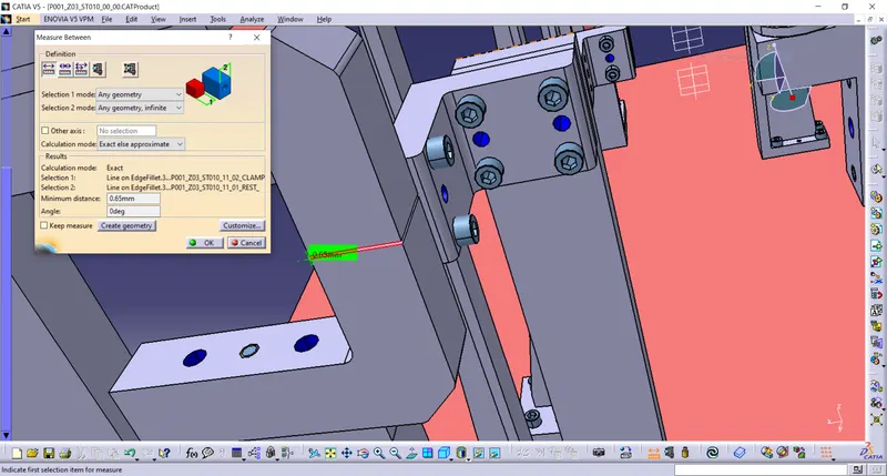
- Gaps Checking: There should be proper and minimum gaps between every surface. That is between panel and units, units and units, weld gun and units etc.
- Fastener implementation: Proper fasteners must be installed in the units from the library of the software. Every standard faterner is available in the library.
- Avoiding clash between different parts: In a fixture, every unit and every part must have minimum gap between them and should not clash or hamper the working of the other unit. This applies to the gun study also. Weld gun position is to be such that the gun does not clash with any of the part. If it clashes, then the position of the gun should be manipulated or the unit should be edited or manipulated.
- Mylar splitting as per panel profile: In case of clamp unit,if we copy a mylar from one location to other, the mylar must be split again with the present surface in order to properly cut the mylar.
- Proper renaming of parts/ assemblies as per the standard: The naming of the parts,components and products should be according to the standard so that other designer is able to understand and work on project.
Rough Locator
A rough locator is a part designed to guide the operator to locate the car panel on thre pins accordingly. A rough locator can be of standard part or make part.
Uses of rough locator
- Rough locator are used to help locate workpiece in the automation process. Locating refers to the desired location where you want the workpiece to be when it is getting worked on either by person,team or robot.
- The accuracy of the locating componenets directly affects the consistancy and how the final product will come out.This is why these components are essential to your setup.
- It can be called as fool proofing method also because due to the rough locator the part can not be loaded in correct position.The rough locators are set according to the angle of the respective panel hence part can only be loaded in defined direction and orientation.
- Rough locators are basically used where manual loading of panels are implemented on the fixture.
- These are used to guide the panels in correct position and orientation.
- Rough locator must never touch the part when it is nested or controlled by the primary tool locator.
- If not required to finish cold/hot rolled steel for rough locator mounting. Use NAAMS standard rough locators when possible.
- Rough locator should have minimal part contact so that the operator can load the part to work location with ease. Excessive part contact may cause difficult part loading and unloading.
- Materials used for rough locators are MS or similar metal.
- These also help for proper poka-yoke.
Following points need to be considered whie designing the rough locators
- Rough locators should be placed ata the edges of the panel which it has to guide.
- Rough locators has to be place in the same angle of the car part edge with minimum distance of 2-5mm from the edge of the car part.
- Rough locator should guide the panel in pin arresting direction.
- Rough locator should start guiding the panel 10-15mm to the start of the pin engagement.
- Rough locator should be designed with entry angle for car part entry.
- Rough locator should be designed with two slots to mount for easy adjustments.
- The slots should be in the direction of car part guiding.
- Height of rough locators should not be more than the permissible ergo height of the fixture.
- The entry point/top point of the rough locator must be 10mm-15mm above the panel surface.
- Rough locators should have adjustment in the direction of guiding plane.
- 2mm gap to be maintained between rough locator and panel at the time of design and we can provide adjustment of 5-10mm in the positive or negative direction of guide palne.
- Rough locators can be rod type or falt type, depending upon the standard and other conditions.
Design Methodology:
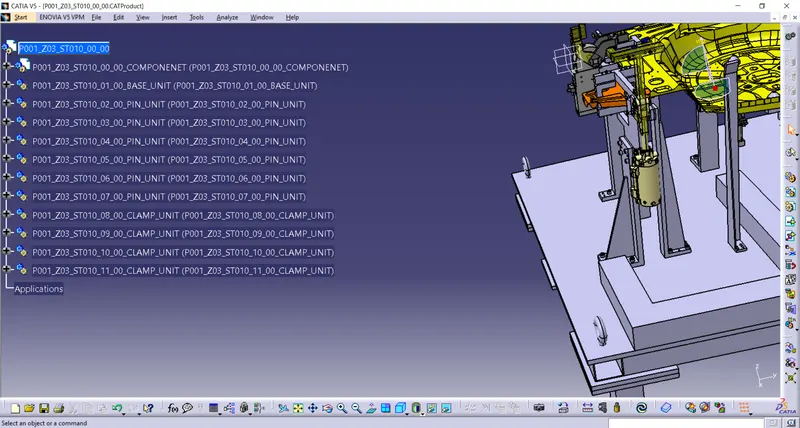
1. Fixture Assembly (P001_Z03_ST010_00_00)
- Renaming and structuring of the design tree
2. Base Unit (P001_Z03_ST010_01_00_BASE_UNIT)
| CHECKING PARAMETER | ACTION |
| Renaming and structuring of design tree | Done |
| Nominality of holes | Done |
| Hole colouring standard | Done |
| Machining area | Done |
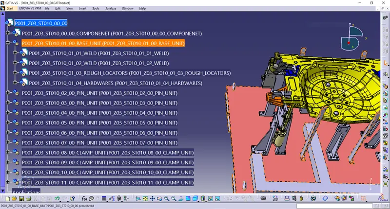
- Renaming and structuring of design tree
- Nominality of holes
- Hole colouring standard
Dowel holes- Blue holes
Threaded holes- Yellow colour
Simple holes- Cyan green colour
Machined Surface- Cream colour
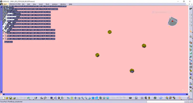
Threaded holes- Yellow colour
- Machining area
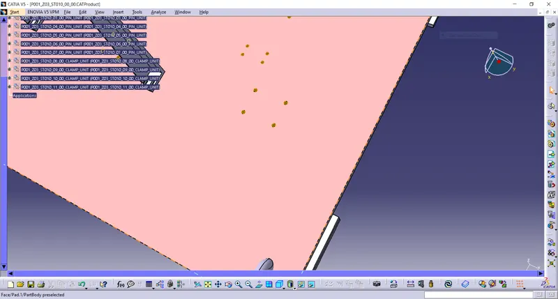
Machined Surface- Cream colour
- Rough locator design
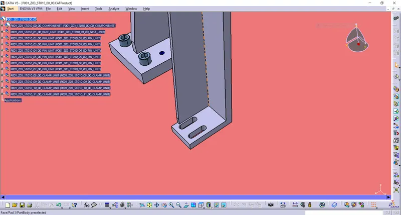
Rough locators are usually used in loading and unloading of particular part.Rough locator unit is a part designed to guide the operator to locate car panel on the pins accordingly.They have slots for adjustment.
Fundamentals of rough locators design
1.Rough locators should be placed at the edges of car panel,which it has to guide using locating pins one can easily restrict movement of entire car panel.
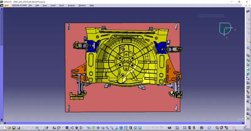
2.Rough locator has to be placed in the same angle of the car part edge with minimum distance of 2.5mm from the edge of the car part,so it should not damage the panel.
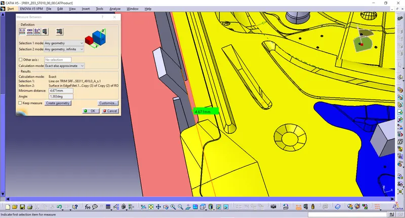
3.Rough locators should guide the panel before 10-15 mm to the start of the pin engagement.
4.Rough locator should be designed with entry angle for the car panel.Generally it ranges between 30-45 degrees.
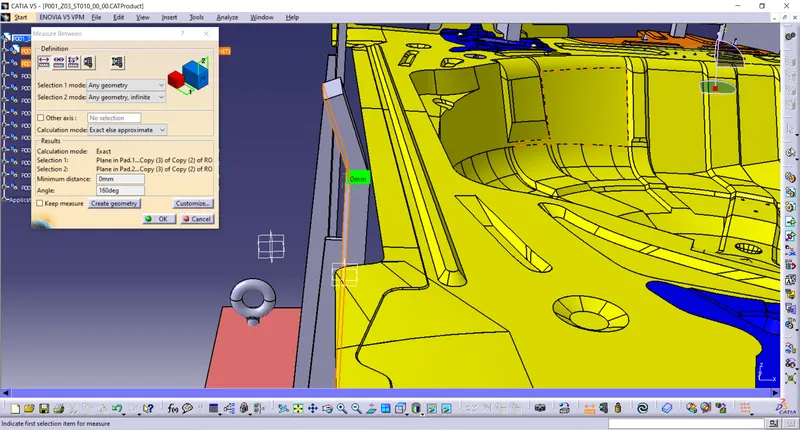
5.Rough locator should guide the panel in pin arresting direction in general.
6.Rough locator should be designed with two slots to mount for easy adjustment.The slot should be in the direction of the car panel guiding.
3. Swivel clamp unit (P001_Z03_ST010_11_00_SWIVEL_CLAMP_UNIT)
| Checking Parameter | Action |
| Renaming and structuring of design tree | Done |
| Nominality of holes | Done |
| Concentricity of holes | Done |
| Hole colouring standard | Done |
| Butting of parts to each other | Done |
| Machined area | Done |
| Mylar splitting as per panel profile | Done |
- Renaming and structuring of design tree
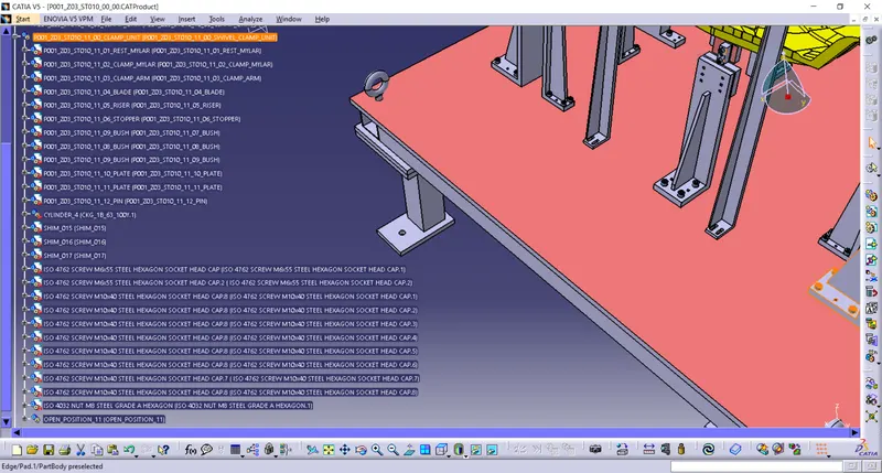
- Nominality of holes
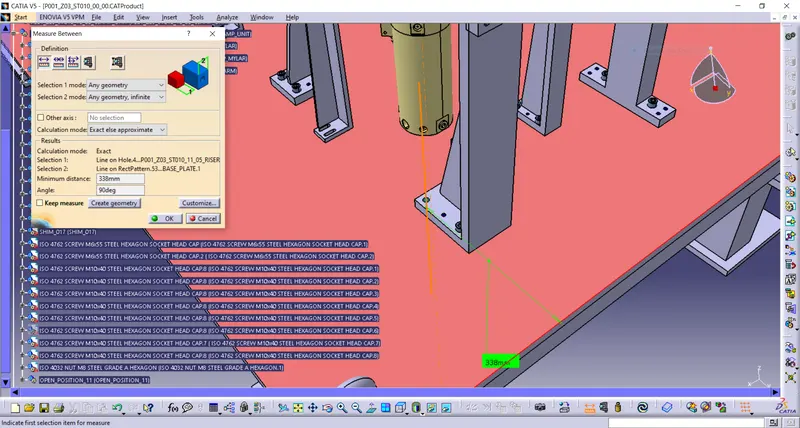
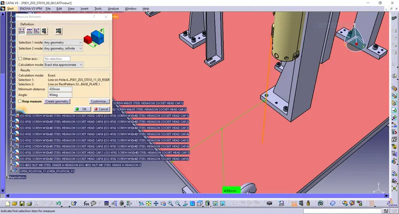
- Concentricity of holes and colouring standard
Dowel holes- Blue holes
Threaded holes- Yellow colour
Simple holes- Cyan green colour
Machined Surface- Cream colour
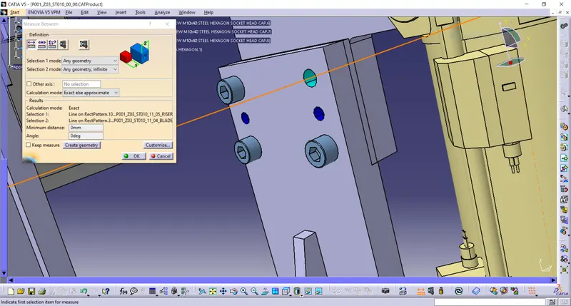
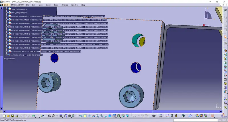
Concentricity of holes Colouring of holes
- Butting of parts to each other
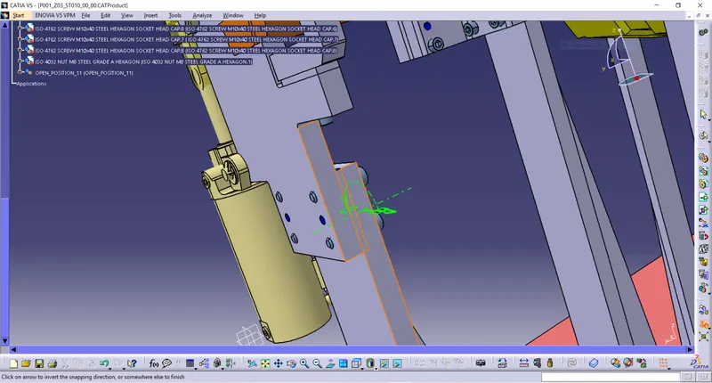
- Machined area
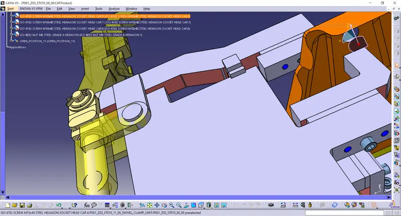
- Mylar splitting as per panel profile
4. Pin Unit (P001_Z03_ST010_02_00_PIN_UNIT) -Retractable
| Checking Parameters | Action |
| Renaming and measuring of design tree | Done |
| Nominality of holes | Done |
| Concentricity of all holes | Done |
| Holes colouring standard | Done |
| Machined Area | Done |
- Renaming and measuring of design tree
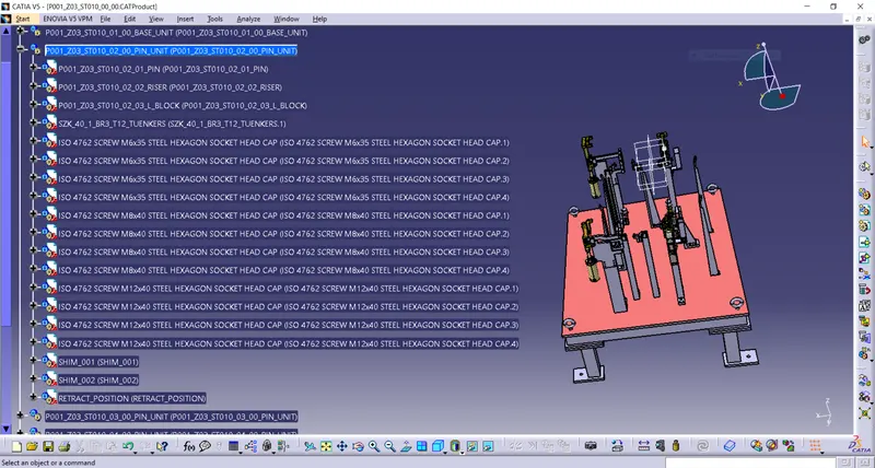
- Nominality of holes
- Concentricity of all holes
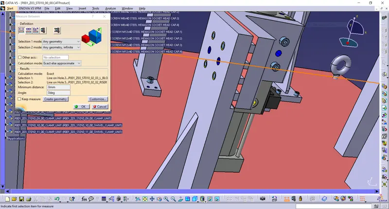
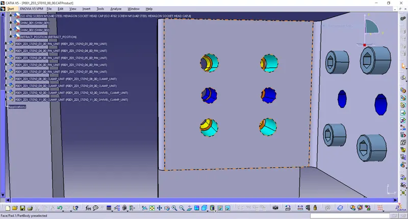
- Holes colouring standard
Dowel holes- Blue holes
Threaded holes- Yellow colour
Simple holes- Cyan green colour
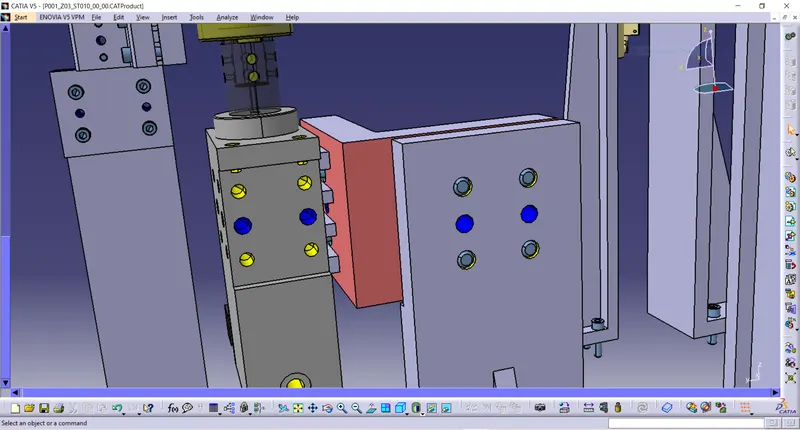
Machined Surface- Cream colour
- Machined Area
5. Pin Unit (P001_Z03_ST010_03_00_PIN_UNIT) - Fixed
| Checking Parameters | Action |
| Renaming and measuring of design tree | Done |
| Nominality of holes | Done |
| Concentricity of all holes | Done |
| Holes colouring standard | Done |
| Machined Area | Done |
- Renaming and measuring of design tree
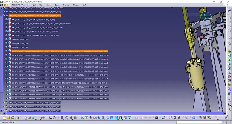
- Nominality of holes
- Concentricity of all holes
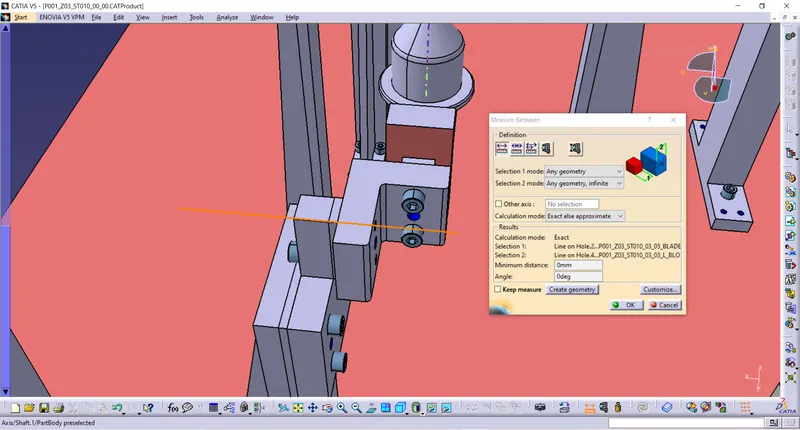
- Holes colouring standard
Dowel holes- Blue holes
Threaded holes- Yellow colour
Simple holes- Cyan green colour
Machined Surface- Cream colour
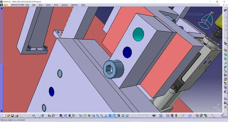
- Machined Area
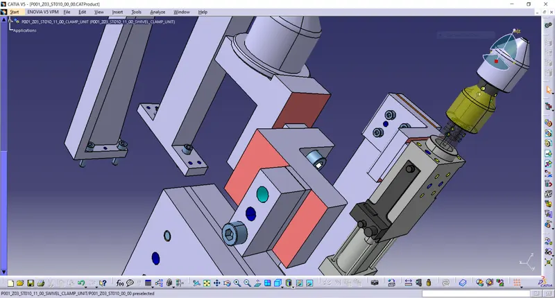
6. Clamp Unit (P001_Z03_ST010_08_00_CLAMP_UNIT)- Power Clamp
| Checking Parameter | Action |
| Renaming and structuring of design tree | Done |
| Nominality of holes | Done |
| Concentricity of holes | Done |
| Hole colouring standard | Done |
| Butting of parts to each other | Done |
| Machined area | Done |
| Mylar splitting as per panel profile | Done |
- Renaming and structuring of design tree
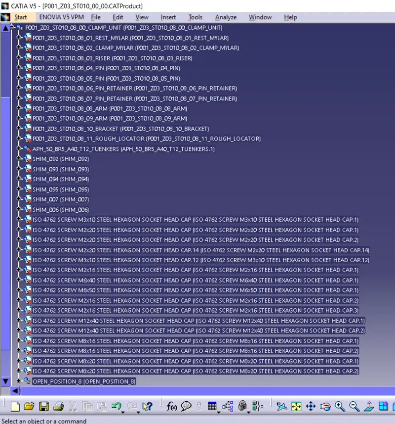
- Nominality of holes
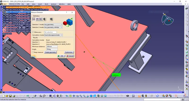
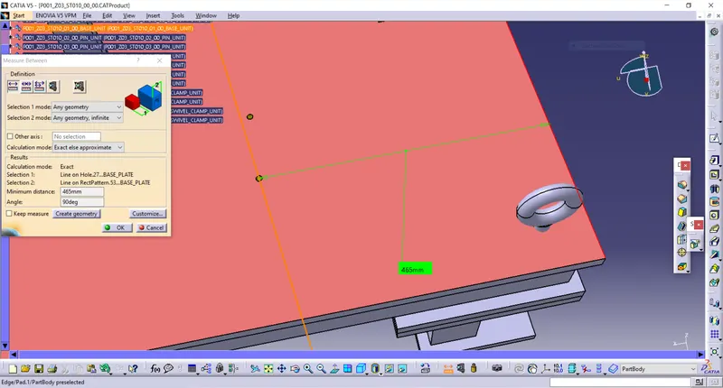
- Concentricity of holes
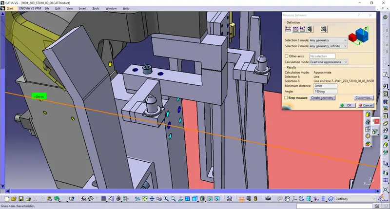
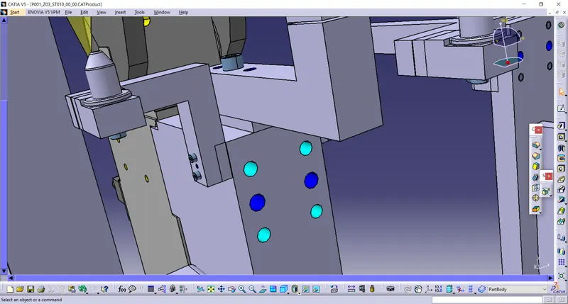
- Hole colouring standard
Dowel holes- Blue holes
Threaded holes- Yellow colour
Simple holes- Cyan green colour
Machined Surface- Cream colour
- Butting of parts to each other
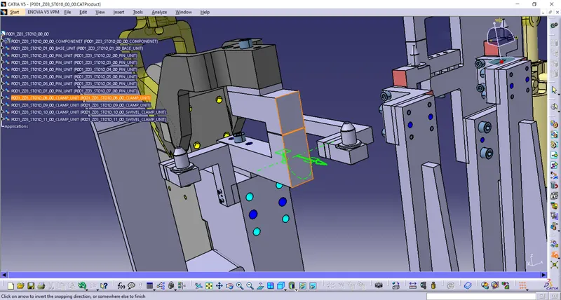
- Machined area
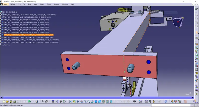
- Mylar splitting as per panel profile
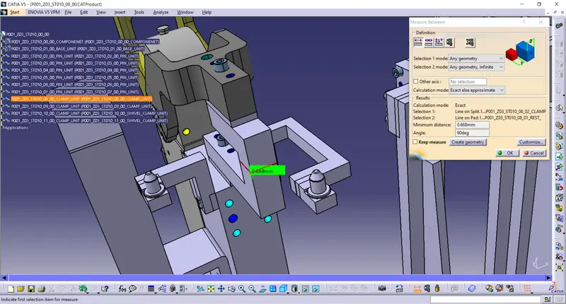
Conclusion
Hence,the 3D finishing is done to the fixture assembly with all the parameters.The file name of 3D finishing project is P001_Z03_ST010_00_00.