Week 8:- 3D Finishing - Challenges 1
1) What do you understand by the 3D finish process?
3D finishing is a process where the design is being completely finish and to be ready for the final simulation and 2D detailing. This is basically the final step and after this the design get freeze.
Following steps are taken care of while finishing the design
- Hole concentricity and hole size: The parts which are to be fastened together should have concentric clearance holes and threaded holes with corrsponding sizes.
- Machining Areas: The surfaces which are to be machined should be represented with proper coloring
- Norminality: The coordinates of the units should not be in demimal. All the units should be edited with respect to base in order to get norminal dimension. Pin units are exception for this as the locationg hole is input from the company and should not be edited unnecessarily.
- Hole coloring standard: The fastening holes and dowel holes should be given standard colors. Dowel hole is navy blue,clearnace hole is aqua and threaded hole in yellow in color.
- Pneumatic Lay-outing: Pneumatic channeling should be provided on the base plate for all the connection which would connect pneumatic cylinders and solenoid valave box.
- Gaps Checking: There should be proper and minimum gaps between every surface. That is between panel and units, units and units, weld gun and units etc.
- Fastener implementation: Proper fasteners must be installed in the units from the library of the software. Every standard faterner is available in the library.
- Avoiding clash between different parts: In a fixture, every unit and every part must have minimum gap between them and should not clash or hamper the working of the other unit. This applies to the gun study also. Weld gun position is to be such that the gun does not clash with any of the part. If it clashes, then the position of the gun should be manipulated or the unit should be edited or manipulated.
- Mylar splitting as per panel profile: In case of clamp unit,if we copy a mylar from one location to other, the mylar must be split again with the present surface in order to properly cut the mylar.
- Proper renaming of parts/ assemblies as per the standard: The naming of the parts,components and products should be according to the standard so that other designer is able to understand and work on project.
2) What are the points need to be taken care of while finishing the design?
Following points are taken into consideration while finishing the design
- Hole concentricity and hole size: The parts which are to be fastened together should have concentric clearance holes and threaded holes with corrsponding sizes.
- Machining Areas: The surfaces which are to be machined should be represented with proper coloring
- Norminality: The coordinates of the units should not be in demimal. All the units should be edited with respect to base in order to get norminal dimension. Pin units are exception for this as the locationg hole is input from the company and should not be edited unnecessarily.
- Hole coloring standard: The fastening holes and dowel holes should be given standard colors. Dowel hole is navy blue,clearnace hole is aqua and threaded hole in yellow in color.
- Pneumatic Lay-outing: Pneumatic channeling should be provided on the base plate for all the connection which would connect pneumatic cylinders and solenoid valave box.
- Gaps Checking: There should be proper and minimum gaps between every surface. That is between panel and units, units and units, weld gun and units etc.
- Fastener implementation: Proper fasteners must be installed in the units from the library of the software. Every standard faterner is available in the library.
- Avoiding clash between different parts: In a fixture, every unit and every part must have minimum gap between them and should not clash or hamper the working of the other unit. This applies to the gun study also. Weld gun position is to be such that the gun does not clash with any of the part. If it clashes, then the position of the gun should be manipulated or the unit should be edited or manipulated.
- Mylar splitting as per panel profile: In case of clamp unit,if we copy a mylar from one location to other, the mylar must be split again with the present surface in order to properly cut the mylar.
- Proper renaming of parts/ assemblies as per the standard: The naming of the parts,components and products should be according to the standard so that other designer is able to understand and work on project.
More points need to take into consideration while finishing the design as follows
- Panel data
- Welding & rivert points
- PPSL Purchase part source list
- PLP- Principle locating point
- Start from NC- Numerical control
- Base mounting positive value
- Buy off sheet
- colour code data
Panel data
- Panel knowledge
- Check mis-assemble in panel
- Number of panel
Welding & rivet data
- Get welding & rivet data from from customer
- Welding & rivet operation process
Process for design
- Sketch should be fully constrained
- Gas cut profile should be in thickness face with edge fillet
- 3mm radius for <50mm thickness
- 5mm radius for >50mm thickness
- If we use 5mm radius for 20mm plate it will remove material is large than 3mm
- Rough machining
- Fine machining
- Maintain 3mm machining step
- Clearnace 3mm between shim and machining step
- In some case 2mm and 2.5mm machining step can use
- Edge fillet 5mm,it depends upon tool diameter
- Avoid unnecessary fine machining
- Holes
NC- Numerical control
- Start from NC
- NC Charping surface should cover 16mm diameter of PLP point
- NC should be in absolute and have round off value in X,Y,Z direction
- NC clamping should be in plain surface (no bend, curved surface), if two or three panel are there, having same PLP the clamping surface must be common for both panels.
- Maintain minimum clearance 15mm between NC (make part) to panel and weld points
- Maintain clearance 10mm, in special case 5mm
- Mention non-magnetic stainless steel if welding point is very close to NC
- Length of NC small in size to avoid vibration
Make part
- Overall length should not be in 0.5 value both horizontal and vertical like 95.5
- Add rib if required to avoid over hanging
- Design weldment in part body or product depend upon number of parts
- Welding clearance
- Weldment clearance minimum 5mm
General check list
- Unit should be in absolute in tool wise
- All NC should be in absolute
- NC face should be round off expect angle NC ( round off in one side)
- Gas cut profile should be there
- Thickness face machining step depends on stock size
- NC dowels should be in slip fit e8 and mounting part should have press fit
- Riser base mounting in slip fit e8
- Hole should be inline
- check clash analysis
- Colour code
- Check 3D properties
3) What are rough Locators & what is their use?
A rough locator is a part designed to guide the operator to locate the car panel on thre pins accordingly. A rough locator can be of standard part or make part.
Uses of rough locator
- Rough locator are used to help locate workpiece in the automation process. Locating refers to the desired location where you want the workpiece to be when it is getting worked on either by person,team or robot.
- The accuracy of the locating componenets directly affects the consistancy and how the final product will come out.This is why these components are essential to your setup.
- It can be called as fool proofing method also because due to the rough locator the part can not be loaded in correct position.The rough locators are set according to the angle of the respective panel hence part can only be loaded in defined direction and orientation.
- Rough locators are basically used where manual loading of panels are implemented on the fixture.
- These are used to guide the panels in correct position and orientation.
- Rough locator must never touch the part when it is nested or controlled by the primary tool locator.
- If not required to finish cold/hot rolled steel for rough locator mounting. Use NAAMS standard rough locators when possible.
- Rough locator should have minimal part contact so that the operator can load the part to work location with ease. Excessive part contact may cause difficult part loading and unloading.
- Materials used for rough locators are MS or similar metal.
- These also help for proper poka-yoke.
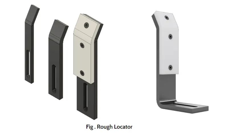
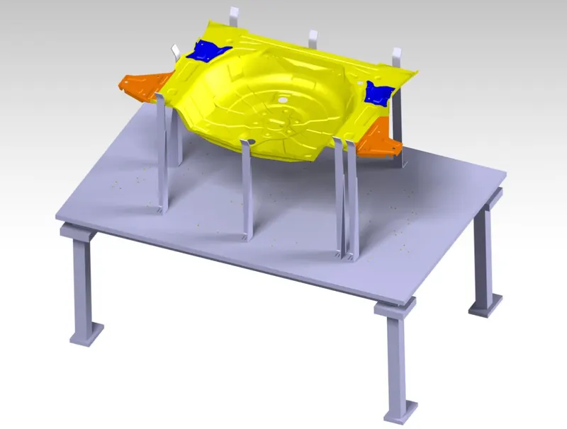
4) What are the points you need to consider while designing a rough locator?
Following points need to be considered whie designing the rough locators
- Rough locators should be placed ata the edges of the panel which it has to guide.
- Rough locators has to be place in the same angle of the car part edge with minimum distance of 2-5mm from the edge of the car part.
- Rough locator should guide the panel in pin arresting direction.
- Rough locator should start guiding the panel 10-15mm to the start of the pin engagement.
- Rough locator should be designed with entry angle for car part entry.
- Rough locator should be designed with two slots to mount for easy adjustments.
- The slots should be in the direction of car part guiding.
- Height of rough locators should not be more than the permissible ergo height of the fixture.
- The entry point/top point of the rough locator must be 10mm-15mm above the panel surface.
- Rough locators should have adjustment in the direction of guiding plane.
- 2mm gap to be maintained between rough locator and panel at the time of design and we can provide adjustment of 5-10mm in the positive or negative direction of guide palne.
- Rough locators can be rod type or falt type, depending upon the standard and other conditions.
5) What is the gun study process?
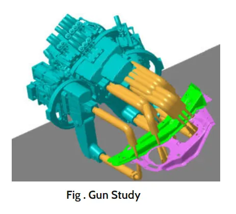
In automotive industry the car panels are predominantly joined by various welding processes. A weld study is performed on the panel to be welded later which includes the required weld spots on the panel. These weld spots are taken into condideration while designing the fixture. Once the design of fixture is completed, the weld gun which we intened to use in actual process is put into the software and the feasibility of the process is checked. This process of inserting the weld gun in the fixture design to check if the position of any part needs to be modified is called gun study.
- Welding is mostly used in automobile industries and their requirement for fixtures that ease the welding process is a continous development task in any industry.
- In weld study process, the major procedure is insert the gun in the tool assembly and place the gun on the weld spots by creating a point on tip, adjust the weld gun for not getting any clashes from the 3D concept.
- Once all the weld spots are cleared without any clashes and it will be moved on to next procedure of simulation.
- In simulation, first we have to check with the reach with respect to the weld spots because robots are also having some limitattion if it exceeds the robot will not work with 100 percent. So first we have move with reach check and then try to adjust the weld gun with respect to 3D concept design, if any clashes get in simulation, we will get cleared with CATIA software.
- Car body in white (BIW) is a complicated steel structure including 300-500 sheets with complex shape and are assembled by means of welding in a high rhythm through 55-75 robotic work stations.
- The fore most step taken before starting the welding fixture design, we must declare weld spots location for each and every panel. The location and orientation of other critical units of the fixture including clamps,location etc are decided based on the weld spot distribution.
Now coming to the point , in weld study, first we have to choose which gun has to be used for welding process, Gun have two different types, they are:
1.) C-Type gun
2.) X-Ttype gun
C-Type gun
In C-type gun one arm side is fixed and another arm is movable in linear direction of perpendicular to other arm (horizontal direction with respect to other arm)
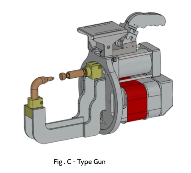
X- Type gun
In X- type gun one arm side is fixed and another arm is movable in angle position like ( it moves like an arc)
It includes the study of weld matrix and the weld points positions. There are two types in weld points one is geo weld which ensures the geometry of the assembly and second is re-spot weld points which adds strength to the welded parts.
The fixture is designed for the car panel to hold it on the position, so we ensure all the weld spots and weld gun do not across or any clashes with fixture tool.
If any clashes defined while designing fixture,then we will only move on to redesign the tool. We have no permission to change a weld spot or clamping position without considering clients.
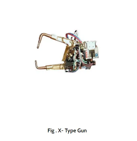
6) What re the points need to consider during the gun study?
Weld gun study is very time consuming process,the entire welding cycle time study depends on the number of spots and the weld gun study.
These are few points which we need to take care when we perform the gun study:
- The axis of weld spot along welding direction must be normal to the weld.
- The gun study should be performed once before the actual simulation.
- The position of the gun should be manipulated first in case of collision with other parts.
- If the position of the gun cannot be manipulated further, the location of the part must be modified or it can also be modified depending on the situatuin.
- The entire given weld points must be cleared.
- During gun study we have to consider client cycle time and we have to maintain the cycle time compared to client requirements. There are two types of weld spots they are:
Geo-spot and respot having different timings
- Geo-spot- 3 sec.
- Respot- 2 sec.
- If we have one or more device models and we want to program, the behavior of each model in the work cell can be simulated over time. Instruction for each device are coded by giving sequence.
- If we have no issue with weld gun and we have to move on to next procedure to run the paths( path ways) to analysis there is any clash while weld gun reach a weld spot and then if we done with that and finally move to sequence of operation.
- After sequencing all the device and paths and finally simulation is run with collision check on and make sure all the weld spots and paths are clear from collision which using safe robots.
7)What is pneumatic routing?
Pneumatic system- System operated with air.
Open loop system.
Generally used for low process.
Generally delivers less force compared to hydraulic system.
Cheaper comapred to hydraulic for basic cost but compressor running cost is more.
Pneumatic system is mostly preferred over hydraulic system in BIW welding fixture.
All toggle clamp,pin cylinder,slides are operted via pneumatic generally cylinder are designed to operate maximum oressure 12-13 bar
As it expensive and difficult to maintain 10-12 bar in shop floor it is preferred to do design pneumatic system at 6 bar pressure.
Proper pneumatic lay-outing or routing is very much important to be shown in design,as it helps in describing the best possible way to keep all pneumatic pipes neat and away from welding spatters which can cause wear or tear of pneumatic pipes.
Various major suppliers for pneumatic itmes are SMC, Teunkers,Festo,CKD etc.
Pneumatic system should be efficient and leak free. Sometimes, they are not because of improper tube line routing which resulted due to either lack of knowledge or corner cut on planning time or both.
Planning tube routing is a time investment but it can have a big ROI, especially for complex systems.During system design,routing should be developed as the next step after sizing the tube lines and selecting the appropriate fittings.
There are some guidelines provided for routing as shown below:
- Leave fitting joints as accessible as possible.Inaccessible joints are difficult and time-consuming to assmeble,tighten and service.
- Use software tools to make labor-intensive calculations such as pressure drop.
- Include offset bends to allow for motion under load,regardless of how rigid the system seems.
- Favor bends rather than straight tube lines,because a straight line tube assembly with no bends,like the example of the test stand mentioned above,can cause joint stain,which may lead to leaking.
- Make sure routing design allow room for assembly of any connections required.
- Minimize pressure drop by getting around obstruction with few 90 degree bends as possible. One 90 degree bend has more pressure loass than two 45 degree bends.
- Route lines around rather than over areas that require regular access or maintenance.
- Design routing with clamping in mind. Appropriate design leads logically to proper clamping. Often,its possible to clamp several lines together.
- Keep troubleshooting and maintenance in mind: focus on logical design and avoid crossed lines.
- Design the tube line routing to reduce likelihood of users standing or climbing on plumbing.
8) What is the solenoid valve?
Solenoid valves are used to actuate the air flow in cylinders as per the sequence through manual or PLC operated system.
A solenoid vlave is an electrically controlled valve. The valve features a solenoid,which is an electric coil with a movable ferromagnetic core (plunger) in its center. In the rest position,the plunger closes off a small orifice. An electric current through the coil creates a magnetic field.The magnetic field exerts an upwards force on the plunger opening the orifice.This is the basic principle that is used to open and close solenoid valaves.
Quick solenoid valve notes:
- Only used for clean liquids and gases.
- Indirect operated valaves require a pressure differential to function.
- Are used to close,open, dose, distribute, or mix the media with 2 or more inlets/outlets.
- Fast acting.
- Options for manual overrides, ATEX, gas approval,media separation and more.
- Can get hot as it requires energy to switch and stay in that position (depending on type).
- Common in heating systems,compressed air,vacuum,irrigation, car washes etc.
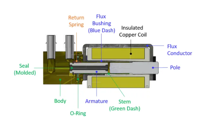
A SOLENOID VALVE
Working of a Solenoid valve
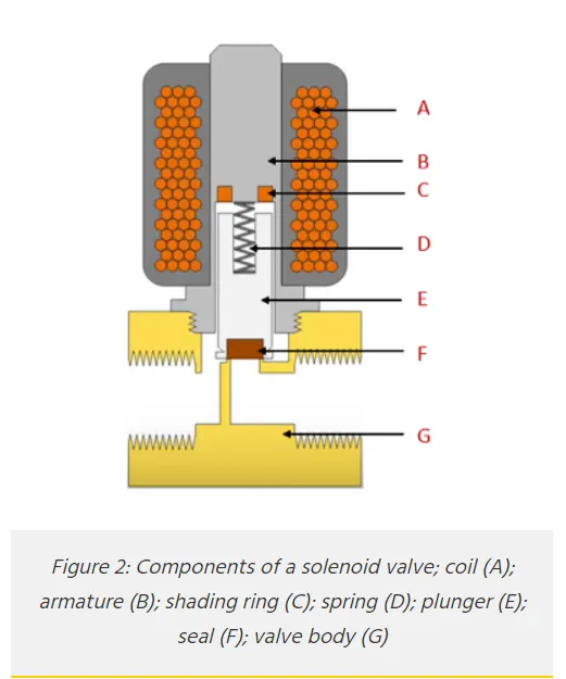
A solenoid valave consists of two main components: a solenoid and a valave body (G). A solenoid has an electromagnetically inductive coil(A) around ana iron core at the centre called the plunger(E). At rest,it can be normally open (NO) or normally closed (NC). In the de-energized state,a normally open valve is open and a normally closed valve is closed. When current flows through the solenoid, the coil is energized and creates a magnetic field. This creates a magnetic attraction with the plunger,moving it and overcoming thr spring (D) force. If the valave is normally closed,the plunger is lifted so that the seal (F) opens the orifice and allows the flow of the media through the valave. If the valve is normally open, the plunger moves downward so that the seal (F) blocks the orifice and stops the flow of the media through the valve. The shading ring (c) prevents vibration and humming in AC coils.
9) What is the valve bank?
Valve banks are basically a system in which n numbers of solenoid valave are mounted in order to maintain one common inlet and outlet of air to all the valves.
Valve banks are mostly mounted on the fixture sides or on the base plate depending upon the various conditions.
Example: If we 4 operating sequence in one process of cylinder,this means we will using 4 solenoid valves,corresponding to 4 different sequences and for these 4 valaves to be mounted together on one valave bank.This means a valve bank with 4+1 valve stations are to be used, 1 extra blank station is taken as a spare for future consideration.
Valve banks are placed in such a way that it can be easily accessible for maintenance purpose.
Valve banks must be properly covered with sheet structure to avoid any damages.
Various major suppliers for valave and valve banks are SMC,Festo,CKD,Janatics etc.
Selection can be done as per the requirement and data sheets availabale on the catalogue or website.
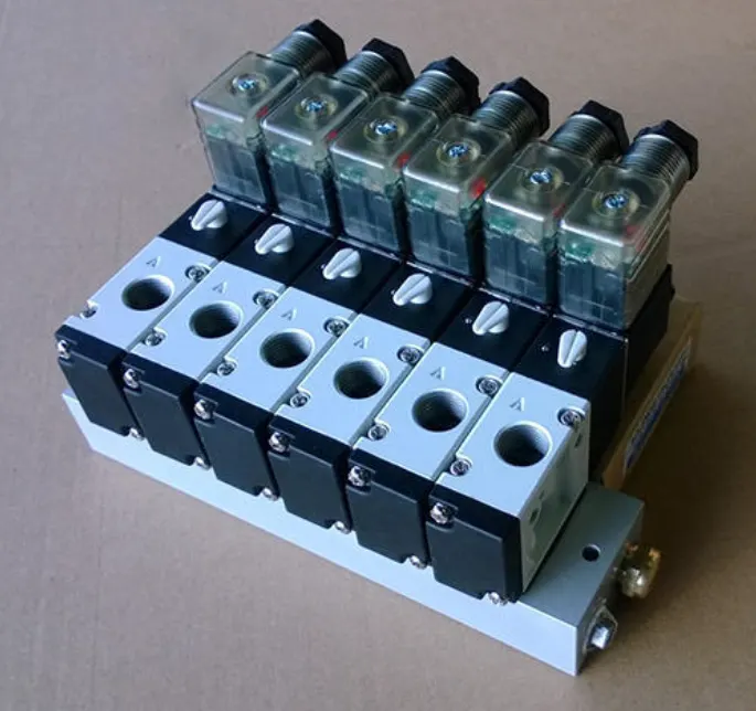
A VALAVE BANK
Common features of valave bank:
- These are designed for high vibration levels.
- It uses aluminium alloy manifold for light weight.
- These are designed for high- temperature environment.
- Design architecture allows easy selection of two to six solenoid valve.
10) What is sensor & brief about its application in automation?
It is a device that converts signals from one energy domain to electrical domain.
A sensor is a device used to sense the car panel by using electrical sensor.This signals formed sensors will be fed to the PLC and so that next process will be executed by this signal.
Sensors also heplps in avoiding the human errors, such as wrong orientation of panel,missing of a panel/part in ana assembly etc.
Sensors are basically used in automated sytems.
Sensors can help us achieve better quality and less chances of errors.
There are wide range of sensors available that can be implemented over various conditions.
Selection of the sensors can be easily done by referring the catalogues or data sheets available on websites.
Sensor in automation
In the industrial automation,sensors play a vital part to make the products intellectual and exceptionally automatic. These permit one to detect,analyze,measure and process a variety of transformations like alteration in position,length,height,exterior and dislocation that occurs in the industrial manufacture sites
These sensors also play a pivotal role in predicting and preventing numerious potenetial proceedings thus catering to the requirements of amny sensing application.
The following are the various types of sensors used in industrial automation: proximity sensor,vision sensors,ultrasonic sensors,position sensors,photoelectric sensor,temperature sensors,inclination sensors etc. The applications for position sensors as a whole are broad.They can be used in anything from motion contraol of a robot,tank-level sensing or even in semiconductor process equipment.
For example displacement sensor is used in the precision positioning of objects at the nanometer level and in the measurement of precision thickness of disk drives,assembly line testing and machine tool metrology. It is widely used in machining.
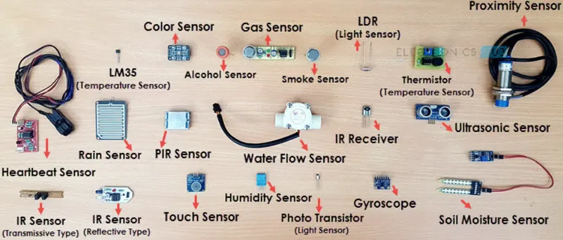
SENSORS
11) What are the types of the sensor?
It is a device that converts signals from one energy domain to electrical domain.
The following is the list of different types of sensors that are commonly used in various applications. All these sensors are used for measuring one of the physical properties like temperature,resistance,capacitance,conduction,heat transer etc.
- Temperature sensor
- Proximity sensor
- Accelerometer
- IR Sensor (Infrared sensor)
- Pressure sensor
- Light sensor
- Ultrasonic sensor
- Smoke,Gas and Alcohol sensor
- Touch sensor
- colour sensor
- Humidity sensor
- Tilt sensor
- Flow and Level sensor
Types of sensors used in BIW
- Proximity sensors
- LASER Sensors
- Photo electric sensors
Proximity Sensors : A proximity sensor is a non-contact type sensor that detects the presence of ana object. Proximity sensor can be implemented using different techniques like optical (like infrared or laser),Sound(ultrasonic)),Magnetic (Hall effect),Capacitive etc.
Some of the application of proximity sensors are mobile phones,car (parking sensor),industries (object alignment), ground proximity in aircraft etc.
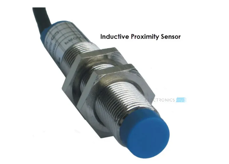
A PROXIMITY SENSOR
LASER Sensors: Laser is a kind of sensor which uses laser technology to measure. It is generally composed of laser,optical parts and photoelectric devices. It can convert the measured physical parameters ( such as length,flow,speed etc.) into optical signals and then use photoelectric converter to convert the optical signals into electrical signals. Through the filtering,amplification and rectification of corresponding circuits,the output signals can be obtained,so as to calculate the measured quantity.
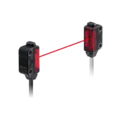
A LASER SENSOR
Photo electric sensors: A photoelectric sensor is a device that detects a difference in the light level received from the light source. The sensor is made up of light source, an amplifier,signal converter and an output. There are three types of photoelectric sensors, thru-beam,retroreflective, and diffused,each sensor has its own strength and can be used in a vareity of ways.
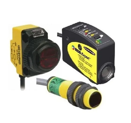
A PHOTO ELECTRIC SENSOR
12) What are the fundamental points that need to consider while designing or selection of sensor?
The fundamental points to be considered while designing or selection of sensors are:
- Sensor unit is unit designed to sense the car panel by using electrical sensors.
- The signal from sensors will be fed to the PLC and so the next process will be executed will be this signal.
- Sensors are used for the confirming there is panel/component present or not.
- It sould help to avoid human erroe.
- Basically sensors should be equal numbers as comapre to number of the panels in a assembly for example if 9 panels are in assembly,so there should be atleast 9 sensors used.
- Sensors slot should be designed in such a way that it can be adjusted in 3 directions.
- Every single loose panel which are being welded in a tool should be sensed.
- Each panel should be sensed by 1 to 2 sensors depend on the size of panel. Preferred to be in diagonal opposite wnds of the panel.
- Every sensor should be mounted in a 3 direction adjustment way in general.
- Some major sensor manufacturers are IFM, Pepperl-fuchs, SICK, Omron etc.