Week 3:- BiW Fixture Design Methodologies Challenges
1.) What is Design Methodology?
Ans.) Design methodology is nothing but the steps followed during the concept designing stages of fixture design.
It is a process to be followed while doing a design. Design methodoly includes different stages from start to end of the designing like purchase order, input from the customer, percentage completion criteria and design output. It gives idea to designer what to design, what are the requirements from the customer, where he/she is stand during designing process and what output need to give from given inputs.
This include design tree in which the name of perticular component or part or assembly will be shown in perticular order (designed parts are at top position and standard parts are at the bottom position)which makes easy for anyone to understand the drawing.
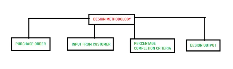
DESIGN METHODOLOGY
- Purchase order
It is basically confirmation from the customer to get ready for designing the fixture.
- Input from customer
Here we get major inputs from the customer like data, specification,quantity and dimention etc. These inputs needs to study and analyze those inputs accordingly.
some examples of inputs given by customer
- Functional requirement
- Preferred standard components
- Car products
- Layout
- Ergo data
- Weld study
- Standard detailing templates
- Percentage completion criteria
Here we decide the schedule at what time we are going to complete the design. It is probability within how much time designing of fixture is going to complete. Here we divide the designing into sub- categories and their time duration to complete so that design can move to next stage without any delay.
Percentage completion criteria is followed in the designing stages and dispatch stages of the welding fixtures
- 0-25 % Input and concept design
- 25-40 % Concept approval and simulation check
- 40-85% Design freezing and detailing
- 85-100% check and final dispatch
- Design output
Here we give output result to the customer in the form of 3D documents, 2D documents, Bill of material, 2D files etc.
The output is 3D models and the 2D drawings of the tools
Unitized tools( multiple units on a common base) requires two types of drawing sheets
key sheet- an index of units and their placements on the tool base
layout sheet- a detailed drawing of individual units to include all of their components
Non-unitized tools- tools tahat can stand alone and acan be detailed completely on a layout sheet.
The output should compile following points
- Approval standard components are to be used whenever possible.
- Design must be as simple & economical as possible.
- Design must comply with all current safety and ergonomic requirements.
- Design must provide for controlled and damage free handling of products.
- Adequate error proofing provision must be incorporated into each design by providing proximaty switches,rough locators etc.
- The weight of the moving parts musst be kept to a minimum while maintaing maximum strength.
- Frames and structures are to be simple and sturdy.
- Design clearance and accessibility for routine maintenanace and service.
- Motion control must be considered in any moving equipments.
- Design is responsible to validate clamp and all weld guns.
2.) What are the inputs required from the customer to start designing a Fixture?
Ans.)
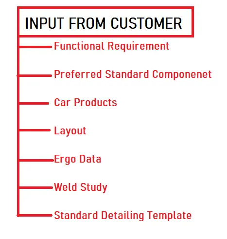
Input from the customer
- Functional requirement- Here all the functional requirements given by the customer to design the particular fixture. Functional requirements includes welding,gluing,riveting and fastening etc.
- Preferred standard components- Preferred standard components are those components which are already available at the customer end and they give their specification to design the component what they already have so that it can save lots of time to manufacture, money investment and efforts to process particular component. If they have any component that we already have their standards,then we don't have to design those particular part.
- Car products- Car products like GD&T, Part list, CAD Files of car part,clam plan and product assembly process sheet are identified or designed in this step.
- Layout- Layout is the arrangement of entire assembly line from start to end which helps to understand the processes and flow of work. It gives the overall idea of assembly of fixture from step to step with pathline.
- Ergo data- Ergonomics refers to study of human behaviour & movements. Each company have their own standards to follow. Customer gives the data to the designer to design the fixture by considering the safety, easy and fool proof design.Ergo data gives information of loading height,working safety zone of operator etc.
- Weld study- Weld study involves the study of particular gun that we are going to use for welding and where it is going to weld and number of weld spots/area. Weld study includes weld gun details and weld matrix and weld points. DIfferent process need different weld techniques like spot welding, seam welding and arc welding etc.
- Standard detailing templates- Every company have their own standards to detail their projetcs so companies gives their detailing templates to designer how to detail the project/component with dimentions.
Functional requirement
- Welding fixture
- Hemming fixture
- Checking fixture
- Storage racks
Preferred standard components
- Standards like ABB,NAAMS,DESTACO,ZYTRAN,TUNKERS
- Standard parts like riser, L-blocks,Retainers,Pins
- Components like clamp,cylinder,slides,switches,sensors.
- Weld gun,tip dresser,tool changer
Car products
- GD&T
- Part list
- Cad files of car part
- clam plan
- product assembly process sheet
Layout
- Flow of parts
- station pitch
- robot station
- accessories like tool changer & tip dresser
- platform height
- loading/unloading sequence/heights
Ergo data
Ergonomics refers to study of human behaviour & movements.
Ergo data information of loading height,working safety zone of operator etc.
Weld study
- Weld study includes
- Weld gun details
- Weld matrix & weld points
3.) What is the input we get from "Car Products"?
Ans.) The major input we get from car products are
- GD&T
- Part list
- Cad files of car part
- clamp plan
- product assembly process sheet
GD&T
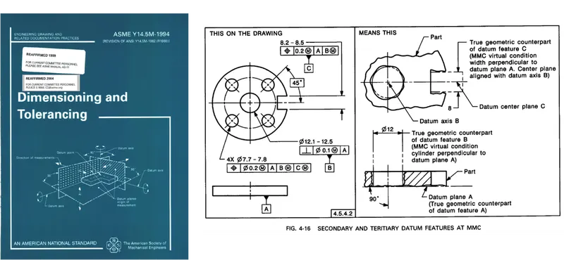
In GD&T, the geometrical dimentioning and tolerances of parts that to be designed. In addition,the information of loacating pins,rests,clamps,Dumps,slide information of each station and sequence of opening of dumps and slide stroke information are also provided.
Part list
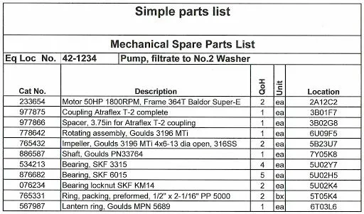
In part list it is mentioned that which asssembly is going to do first with their respective parts. Here we get all the information with part name and part number in sequence to assemble.
Cad files of car part
CAD files of car part means that 3D component that we require from all the CAD parts.
Clamp plan
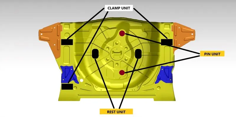
Clamp plan is the important data that we get in designing input. It tells the position where the clamp should place for assembly. We should never change the position of clamp during designing otherwise it may defect the whole assembly. We can change in our design little bit but we should not change the input design data about clamp position or pin position.
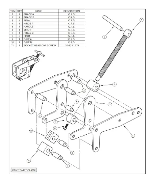
Product assembly process sheet
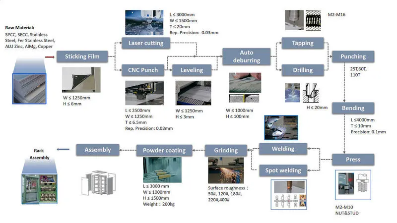
In product assembly process sheet we get all the information which products are going to assemble in particular component unit. The sequence of assembly and stages of assembly are properly shown in the sheet.
4.) What is the Clamp plan?
Ans.)
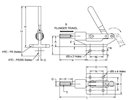
A clamp is force-actuating mechanism of a fixture. The forces exerted by the clamps hold a part securely in the fixture against other external forces. Clamping surfaces are subjected to the clamping for obtaining invarient location. A clamp is a fastening device used to hold or secure object tightly together to prevent movement or separation through the application of inward pressure.
Clamp plan is the important data that we get in designing input. It tells the position where the clamp should place for assembly. We should never change the position of clamp during designing otherwise it may defect the whole assembly. We can change in our design little bit but we should not change the input design data about clamp position or pin position.
Requirement of clamp
- All clamps must fullfill four essential requirements. They are.
- The work piece must be held rigid while undergoing operations.
- The time required for loading/unloading the tool must be as short as possible.
- Whwn subjected to viberation,chattered,heavy pressure the claming must be positive.
- The clamp must not damage the work piece.
5.) What is the purpose of a Layout?
Ans.) The way in which the parts of something are arranged or layout. The purpose of the layout is to understand the information about where the fixture and robots are been placed,working area covered by the robot, what are the fixturea assigned for the robots to do the process etc. Layout shows the entire assembly plan to understand the process. The circle around the robot is the swept area of the particular robot which shows the reachability of the robots particularly with the confine circle.
The layout gives the following deatils
- Flow of parts- Layout gives the information of flow of parts from one station to other station with some operation to be done.
- station pitch- Station pitch gives the information how much the distance of particular station covers in assembly floor.
- robot station- It tells the location of robot stations in assembly floor
- accessories like tool changer & tip dresser- It gives the information about all accessories are associated with assembly process like tool changer and tip dresser.
- platform height- It gives the information of platform height of each station to do particular operation.
- loading/unloading sequence/heights- All the movements in assembly shows here like loading and unloading of parts and what are their sequence of handling from one station to another station.
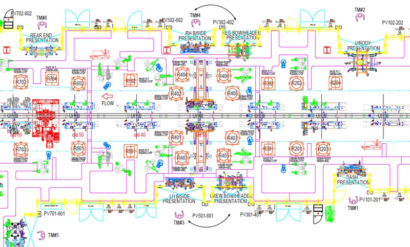
By considering the layout,the designers can develop the concept sketches of fixtures without any clash in the assembly lines.
The layout providing the above information like flow of parts, station pitch, robot station,etc. used to understand the working process of robots, what are the fixtures assigned for the robots, space constraint etc.
6.) What is Ergo data?
Ans.) Ergonomics refers to study of human behaviour & movements.
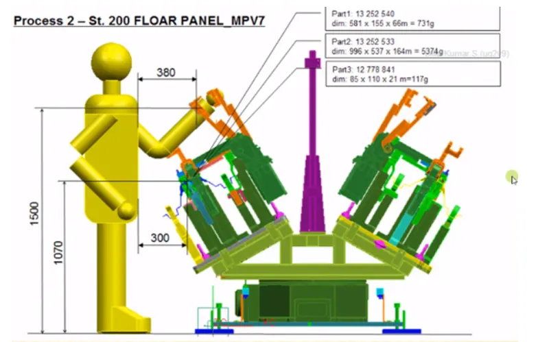
Ergo data information of loading height,working safety zone of operator etc.
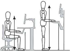
Ergonomics is the science of refining the design of products to optimize them for human use.Human characteristics,such as height,weight,and proportions are considered,as well as information about human hearing,sight,temperature preferences and so on. Ergonomics is sometimes known as human factors engineering.
The word ergonomics comes from the greek word 'ergon' which means work and nomos means laws.It's essentially the 'laws of work' or 'science of work'
Ergonomics draws on many disciplines to optimize the interaction between the work environment and the worker.
The final assembly of an automobile involves tasks of complex nature. These processes are on the least priority for automation. Manual labor is best suited for assembly operations with the aid of minimal level of automation. All the processes have to be improved continuously in order th reduce the costs and increase productivity. The worker attain various postures,exerts force and works continuously in cycle time to accomplish the assembly task. Working along automobile assembly lines is characterized by repetitiveness.
Benefits of ergonomics
- Lower costs
- Higher productivity
- Beteer product quality
- Improved employee engangement
- Better safety culture
7.) What do you understand by Weld study?
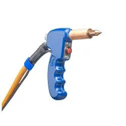
Ans.) Weld study is a procedure in assembly of componenets where the study of weld gun happens and where it is going to weld on the component and what kind of welding method is going use eg. spot welding,seam welding etc. also about how many number to weld is going to happen on particular component.
Weld study includes
- Weld gun details
- Weld matrix & weld points
A) Geo weld points
b) Re-Spot weld points
Weld study includes
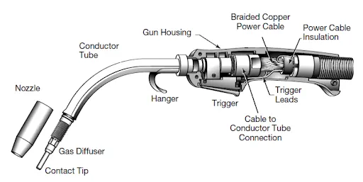
Weld study of gun includes the details of weld gun where to use and where it is going to use in assembly line.
Weld matrix & weld points
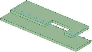
Weld points are the points where the exact point of welding is going to happen on component. It tells exact co-ordinate point with respect to X,Y,Z plane.
Geo weld points & Re-Spot weld points
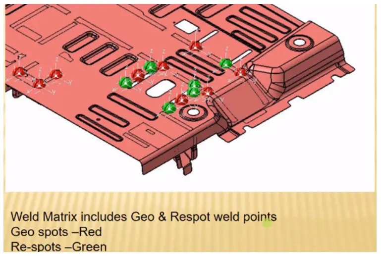
The data of geo weld matrix and weld points designer recieve from the customer end. In data it is all mentioned in the form of different spot colours like red and green.
Geo weld points respresented by red spot and gets weld at geo-station where re-spot weld points represented by by green spot and weld at re-spot station. This generally happens when one component is to be assembled at one station and other component is to be assembled at different station.
8.) What are the criteria for percentage completion in the designing stage? Explain it in details.
Ans.) Here we decide the schedule at what time we are going to complete the design. It is probability within how much time designing of fixture is going to complete. Here we divide the designing into sub- categories and their time duration to complete, so that design can move to next stage without any delay.
Percentage completion criteria is followed in the designing stages and dispatch stages of the welding fixtures.
Percentage completion criteria divided into four stages as follows.
1) 0-25 % Input and concept design- Here we get input from the customer end and designer study all the input data with respect to, it creates a concept design for fixture. Upto this work it defines the 25% of work is completed in designing process. Here we are given four days to complete this much of work as dead line.
2) 25-40 % Concept approval and simulation check- Here concept of design gets approval from the customer after simulation check. Till here 25 -40% of work gets completed in designing.
3) 40-85% Design freezing and detailing- After concept of design gets approval from the customer end we finalize the design and done with detailing of design. Till here upto 85% of design gets completed here.
4) 85-100% check and final dispatch- After finalizing and detailing to design, quality team checks all the data. Is correct as per customer requirement? If everything is ok, it dispatch to customer.
9.) Brief about "Output" in design?
Ans.) In BIW fixture design or in any designing industry, firms dont give only design of component and its CAD file to the customer. Here we submit a lots of documnets like 3D documents, 2D documents and BOM which details the components in every aspect.
- The output is 3D models and the 2D drawings of the tools
- Unitized tools( multiple units on a common base) requires two types of drawing sheets
- Key sheet- an index of units and their placements on the tool base
- Layout sheet- a detailed drawing of individual units to include all of their components
- Non-unitized tools- tools that can stand alone and can be detailed completely on a layout sheet.
Design and development output should be
- Meet the input requirements for design and development
- Provide appropriate information for purchasing,production and for service provision.
- Contain or reference product acceptance criteria.
- Specify the characteristics of the product that are essential for its safe and proper use.
Unitized Tools
In the unitized tools testing requires two type of drawing sheets, one is key sheet and other is layout sheet.These sheets are an index of units and placements on the tool base. Layout sheet is a detailed drawing of that particular tool which shows details of components and how and where it is to be placed.Key sheet shows the placement and location of that particular tool on the tool base where exactly tool is placed and what is exact position in a particular place.
Non-Unitized Tools
Non-Unitized tools are the tools like stands and tool changer where you dont need key sheet. Tools that can stand alone and can detailed completely on a layout. We can use layout sheet and complete the entire documentation of the particular component.
10.) What do you understand by structuring a design tree? How does it reduce errors during the design process?
Ans.) Structuring a tree in design is a process where the assemblies are given with certain name and their parts which is going to assemble in them. These are well structured in such a way that anyone can understand the design easily. The basic structure followed in structuring tree design is under the product there are main assemblies, sub-assemblies, child part, standard parts etc. these are all parts are provided with specific number,zone etc. to identify easily.
- Structuring a design tree implies to a process where all the assemblies and parts are named in a sequence standard. Different customers have different set of standards to structure a design tree.
- It is an important process which hepls us to identify a specific part or assembly as to which project.tool,or,unit,it belongs to.
- This hepls us to avoid the error during design study,manufacturig,assembly,inspection etc.
- If the parts or assemblies are not named properly or the design tree is not structured properly,it will create confusion to understand the design and amy create major possiblities of making an error.
- Naming of a fixture or a unit or a part,gives the information as to which project or zone or assembly do they belong.
- It can help us to identify the quantity of items of some type or different types taht are being used in an assembly.
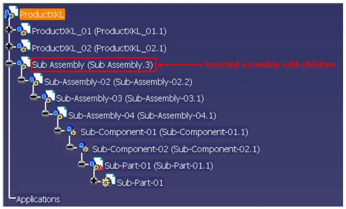
Steps for structuring the design tree
- Create new product a click OK (by clicking ok now you will enter into a product window)
- Then right click product in a structure tree a go to properties a rename in part number ( As we created a product we have to mention the total assembly name of the fixture) a click ok.
- The naming of the assemblies/part/units have certain standard procedures,which i have clearly explained below.
- The product name of the fixture.The renamed titled should be a P001_Z03_ST09_00_00_RP001- represent the project name, Z03- Zone name, ST09- station name, 00- unit name, 00- part number.R/L- is representing the right hand side/left hand side of the panel.
11.) What are Units? Mention 5 types of units.
Ans.) A unit is a device that has a specified function, especially one forming part of a complex mechanism. BIW fixture is of different units which are designed to fullfill different purpose. In units they are two types one is unitized tools and non-unitized tools.
Different unit have different function like resting the panel, clamping the part, locating the part etc. According to the 3-2-1 principle of fixtue design the units are designed to locate and clamp the car panel to its specified position in the fixture while operation.
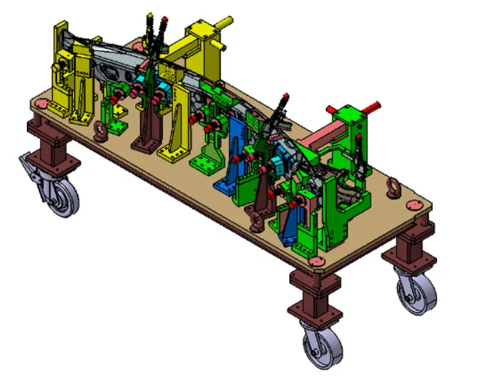
Different types of units are as follows
- Fixed pin unit
Fixed pin unit is a unit designed to locate the car panel using pins.
Fixed pin unit have different parts like pin, pin retainer, shims/spacers,block,blade/adaptor plate and riser.
Pin- The top most sharp part of the unit is called pin.
Pin retainer- It is used to hold the pin firmly.
Shims/Spacer- It is used for adjustment of tolerances or to correct the position of pin.
Block- To hold the upper part of body which contains pin, pin retainer and shims.
Blade- To give proper position to the pin accordance to requirement and to give some height.
Riser- It helps to give some height from the base.
- Retract pin unit
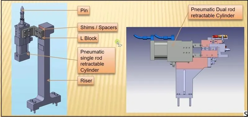
Retract pin unit also used to designed to locate the car panel using pins but it has bi-lateral motion of pin in opposite direction with the help of pneumatic mechanism.
It is mainly used during unloading after welding the components.
It is used mainly when two components are to be joined when they are at different angles.
Retract pin unit have different parts like pin, shims/spacers, L block, Pneumatic mechanism and riser.
Pin- The top most sharp part of the unit is called pin.
Shims/Spacer- It is used for adjustment of tolerances or to correct the position of pin.
L block- To adjust the position of pin in both direction.
Pneumatic mechanism- With the help of this pin moves in reciprocating motion.
Riser- It helps to give some height from the base.
- Rough locator unit
A rough locator is a part designed to guide the operator, to locate the car panel on to the pins accordingly. A rough locato can be of atandard part or make part.
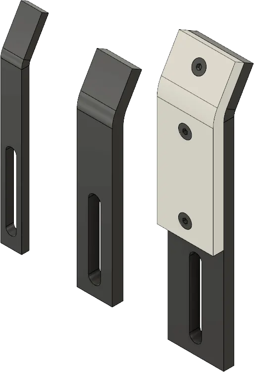
- Rest unit
The panel rest on this unit.
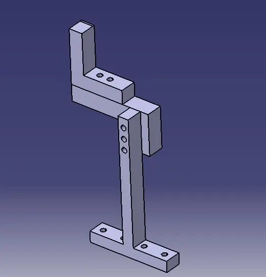
- Base unit
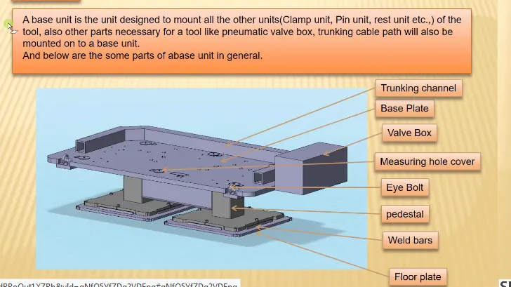
Base unit is design to mount all other units on it like trunking channel, base plate, valve box, measuring hole cover, eye bolt, pedestal, weld bars and floor plate.
12.) Describe Fixed Pin units & their purpose?
Ans.) Fixed pin unit is a unit designed to locate the car panel using pins and find below are the different parts of a fixed pin unit in general.
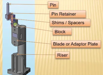
Fixed pin unit is a unit designed to locate the car panel using pins.
Fixed pin unit have different parts like pin, pin retainer, shims/spacers,block,blade/adaptor plate and riser.
Pin- The top most sharp part of the unit is called pin.
Pin retainer- It is used to hold the pin firmly.
Shims/Spacer- It is used for adjustment of tolerances or to correct the position of pin.
Block- To hold the upper part of body which contains pin, pin retainer and shims.
Blade- To give proper position to the pin accordance to requirement and to give some height plus other parts mounted on it like cylinder, arms etc.
Riser- It helps to give some height from the base.
Purpose of fixed pin unit
- Fixed pin unit is a unit designed to locate the car panel using pin.
- The fixed pin unit is the part of the 3-2-1 principle.It restricts 6 degree of freedom of the car panel.
- It is necessary to have 2 pins to locate car panel one pin must arrest 4 way (4 TRANSLATIONAL) & other must arrest 2 way (2 ROTATIONAL) of a car panel.
13.) What are the different parts of a fixed unit?
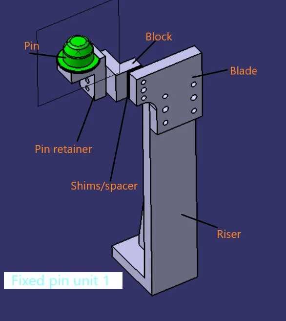
Ans.) Different parts of the fixed pin units are a s follows
- Pin
- Pin retainer
- Shims
- Blade
- Riser
Pin
The top most sharp part of the unit is called pin. It is used for the location purpose of the panel.
The body part is constrained by a set of appropriately locating pin so total constraint by locating pin should be fully constrained at all times to prevent any movement.
Pin retainer
It is used to hold/support the pin firmly.
Shims/Spacer
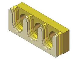
It is used for adjustment of stackup tolerances or to correct the position of pin. It is thin slab like structure with thickness of 0.1mm,0.2mm and 0.5mm etc.
Blade
To give proper position to the pin accordance to requirement and to give some height plus other parts mounted on it like cylinder, arms etc.
Riser
It helps to give some height from the base.
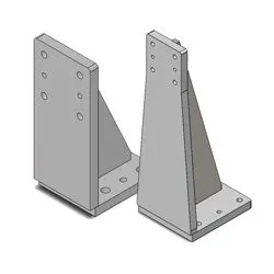
14.) What is the purpose of making a Rest unit & describe its parts?
Ans.) A rest unit is a unit designed to rest/support the car panel using NC blocks/Mylar/ Rest and below are the different parts of a rest unit in general.
The rest units are designed to rest/support the car panel by using NC blocks/Mylar/Rest. It is the simplest unit to design with less parts because of simplicity the rest unit is combined with other unit to reduce the cost of the overall project. It can be combined with locating unit to locate as well as to rest the car panel also locating,clamping and rest unit can be together in one unit to reduce the cost.
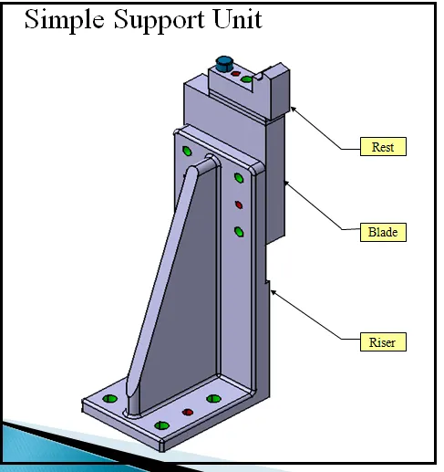
Parts of rest unit
- NC blocks/mylars
- Risers
- Blade
- Shims
NC blocks/mylars
Mylars are the parts in rest unit which holds the panel from top and bottom.
It is jaw type,during welding it wont deforms from its position. It also known as fingers.
Mylars are of two types mainly first one is clamping mylar and other one is resting mylar. Only resting mylars acn be seen in rest unit. The panel which rests on the part is known as resting mylars.
Riser
It is standard part which is used to rise and to give some height to the whole unit.
Blade
These are plates which are mounted on the riser. It support other parts too like cylinder and arms etc.
Shims
It is used for adjustment of stackup tolerances or to correct the position of pin. It is thin slab like structure with thickness of 0.1mm,0.2mm and 0.5mm etc.
15.) What are the basic fundamentals to design a Sensor unit?
Ans.) A sensor unit is a unit designed to sense the car panel by using electrical sensors.This signals from the sensors will be fed to the PLC and so that next process will be excuted by the signal.
Sensor is a device which detects or measures a physical property and records,indicate, or otherwise responds to it.
There are different types of sensors
- Proximity sensor
- Laser sensor
- Photo electric sensor
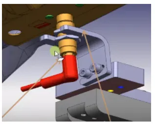
Fundamentals to design a sensor unit
- Every single panel which are being welded in a tool should be sensed.
- Each panel should be sensed by 1 or 2 sensor depend on the size of the panel,preferred to be in diagonal opposite ends of panel.
- Evey sensor should be mounted in a 3 direction adjustable way in general.
- We should try to minimize the size of sensor as much as possible.
- Some major manufacturers are IFM,Pepperl-Fuchs,sick,OMRON etc.
16.) What is a Rough locator unit & what are the basic fundamentals to consider while designing it?
Ans.) A rough locator is a part designed to guide the operator, to locate the car panel on to the pins accordingly. A rough locator can be of standard part or make part. It can be called as fool prooofing method also because due to the rough locator the part cannot be loaded in correct position.The rough locator are set according to the angle of the respective panel hence part can only be loaded in defined direction and orientation.
Fundamental of rough locator design
- Rough locator should be placed at the edges of panel,which it has to guide.
- Rough locator has to be place in the same angle of the car part edge with a minimum distance of 2-5mm from the edge of the car part.
- Rough locator should guide the panel in pin arresting direction.
- Rough locator should start guiding the panel 10 to 15 mm to the start of the pin engagement.
- Rough locator should be designed with entry angle for car part entry.
- Rough locator should be designed with two slots to mount for easy adjustment.
- The slot should be in the direction of car part guiding.
17.) What is a Base unit and describe it's parts?
Ans.) A Base unit is design to mount all other units on it like trunking channel, base plate, valve box, measuring hole cover, eye bolt, pedestal, weld bars and floor plate.
Floor plate: It is the plate which join the fixture to the floor by using some nut bolts. This plate surface is machined for maintaining the horizontal position of the fixture.
Weld bars/pedestal: Pedestal/Weld bar is the base or support on which the fixture is mounted.
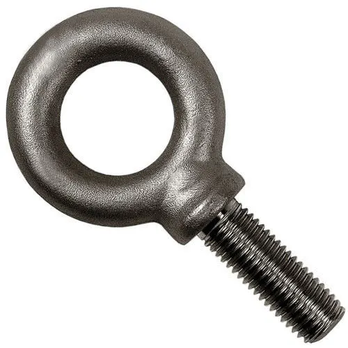
Eye bolt: An eye bolt is a bolt with a loop at one end. They are used to firmly attach a securing eye to a structure,so that ropes or cables may then be tied to it.Machinery eye bolts are fully threaded and may have a collor,making them suitable for the use with angular loads up to 45*.Eye bolts without a shoulder should not be used for angular loads.
Measuring hole cover: The base plate has some drills to mount various units like clam,rest,pin etc. and every drill have some coordinates to define the exact location of the hole.Due to irregular shape of the car panel the drilled holes coordinates are not like 110.0,150.0 but like 110.62,150.84. The measuring hole is drilled over the base plate which having exact coordinates so that all other holes can take reference from it.The measuring hole number depends on the size of base plate.These holes are covered by using some plate to protect against dust,damage etc.
Valve box/trunking channel: The valve box is the box which include different solenoid valves. The pneumatic fixtures work on air pressure provided to it. So, the arrangement of air pressure inlet & outlet is done within this valve box. The trunking channel includes all the pressure inlet cables going to the pneumatic parts of the fixture and protects them from damaging while operation is in process.
Base plate: Base plate is the heavy plate of large thickness because it carries all the weight of the mounted parts,so it must be able to bear the load. Base late is machined to maintain the parallelism within the tolerance.It also consista some drilled holes to mount the different units over it.
18.) What is a Dump Unit and what are its functions?
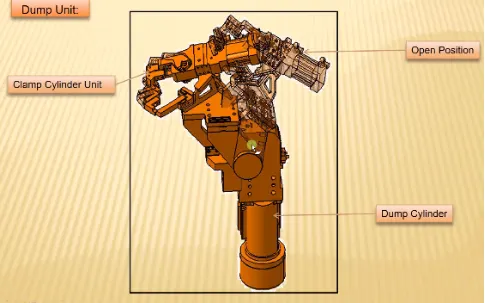
Ans.) Dump unit is the complex unit to design due to space constrains there is less space available and have to adjust all the pats in available space.It consists of dump cylinder to perform the operation of clamping and unclamping car panel.
Function of dump unit
If you have particular constrint and you can not assemble in a normal way then dump unit comes into action. It has dump cylinder and it has open position and closed position. It has clamp cylinder unit too that is why this is very complex in design.If you have any geometrical constraints,you can use this dampener to constrain your components.
Dump unit plays as a vital role when there is any geometrical constrains while placing a panel.
19.) What is a Slide unit? Mention where Slide units are commonly used.
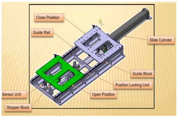
Ans.) A slide unit is absically used in space constrains in assemblies a part. This unit is also a complex unit. It contains sliding bed, cylinder, open position, close position, guide box, position locking unit, sensor unit, stopper block. Slide units are positioning units which are used to position the fixture,weld gun, units, robots into the position for further operation.
Components of a slider unit
- Sliding cylinder: sliding cylinder has one position and one closed position,which has to guide rails direction to the entire panel is going to move.
- Position locking unit: Position locking unit which will lock the position at that particular point doesn't allow the entire plate to move.
- Sensor unit: Sensor need to sense whether this entire component has reached here or not.
- Stopper blocks: Stopper blocks used to control the entire panel moving and it's a moving part.