Week 2:- BiW Fixture Basics Challenge
1.) What is the process of project execution activity?
ANS.) The project activities which are involved in BIW designing/ Manufacturing are as follows. Its shows the flow of procedure from RFQ received to finished product delivered to customer end.
Below the flow of process shown here
- Request for quotation
- 1st spec discussion meeting
- Offer submission
- LOI/PO receipt (letter of intent/ project order)
- Schedule preparation
- BOM preparation (Bill of material)
- Design concept preparation
- Customer approval
- Detailing and drawing release
- Manufacturing/ BOP ordering (Balance of payment)
- Mechanical/electrical assembly
- Quality inspection
- Internal trail & testing
- Online trial
- Packaging
- Dispatch
- Installation as per layout
- Trial & training at customer
- Buy off meeting
- Final handover
- Request for quotation – This is the first foremost step where firm gets the RFQ from the customer in the form of data or documents. Requirement of customer is shown here what actually he wants as a final product. Here he quote his specification, technical offer and commercial offer and other detailing in the form of documents.
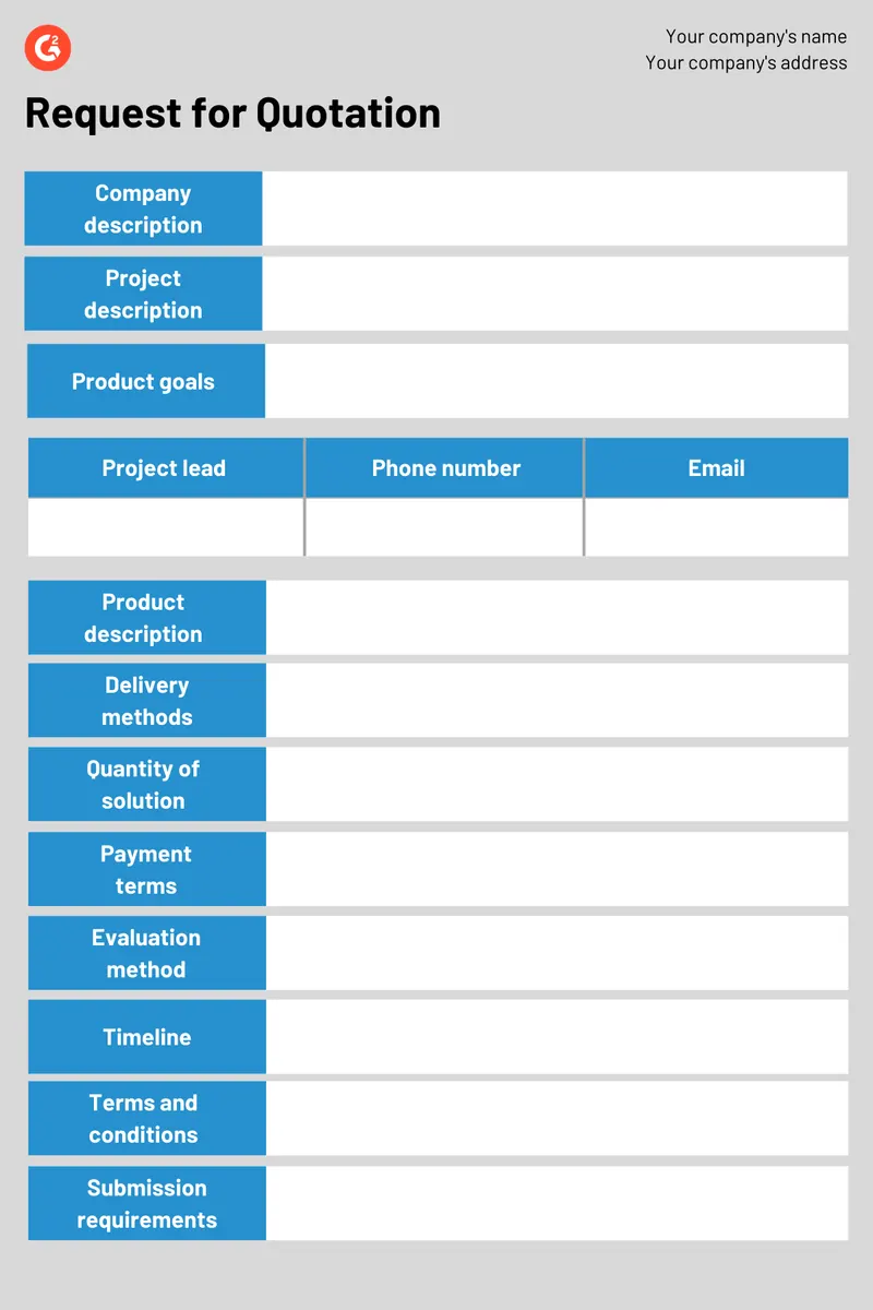
- 1st specification discussion meeting - Here after receiving the RFQ engineers study the requirement of customer and give technical offer or commercial offer. Here documents are being made about technical details and show how much time is required to proceed or work to be done. Main discussion is about timeline and cost that is recquired in this project.

- Offer submission – After making the technical details and time duration for wok process, offer submission happens, where customer analyzes their requirement is being fulfilled or not. Is my work happening in time? Is offer is beneficial to him or not? And here designing/manufacturing firm confirm the order.
- LOI/PO receipt (letter of intent/ project order) – Once the offer given to customer, he checks for technical specification as per his requirements and check for technical offer and commercial offer given by different firms.
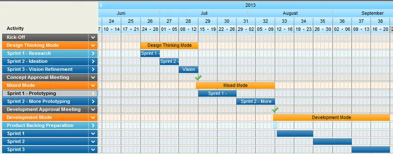
- Schedule preparation – Dividing the work into different work plan into some time frame like PO received, kick-off concept/process design, design data study, 3D design preparation, simulation etc. to complete the project in deadline. Here each process is defined by some time frame to complete perticular process.
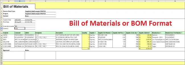
- BOM preparation (Bill of material) – Here we identify how many parts/materials or machines are required like motor, cylinder etc. in designing fixture.
- Design concept preparation – Here we design our concept based on data and technical details arrived form customer end and sent to customer for approval.
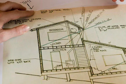
- Customer approval - Here we get approval of design from the customer. Customer sees is that design as per his requirement and check all technical details meets his need.

- Detailing and drawing release – Here detailing of fixture design happens as per customer need like specification,quantity and design after detailing final drawing get release.
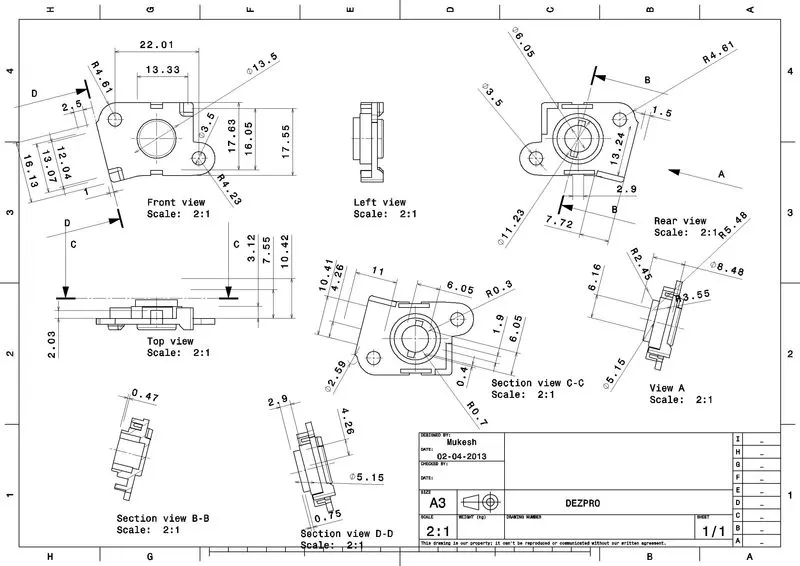
- Manufacturing/ BOP ordering (Balance of payment) – After drawing get released manufacturer of fixture starts manufacturing parts like riser, Mylar etc as per design specifications and also here ordering of material like cylinder, sensor are given as per requirement.
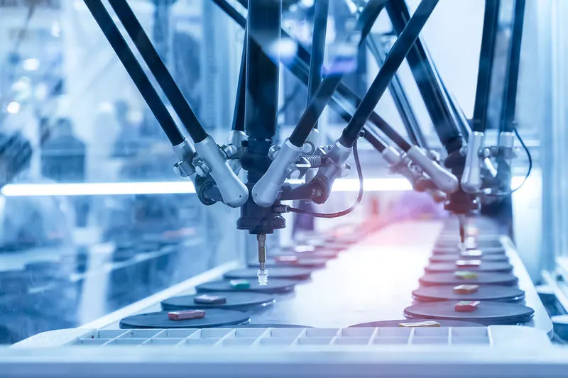
- Mechanical/electrical assembly – Here mechanical and electrical assembly happens as per requirement and design.
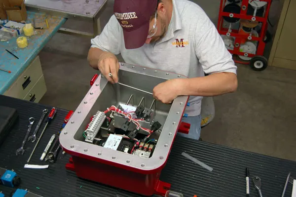
- Quality inspection – Here quality department check is the assembly is same as per design, all the dimensioning is proper or not and do CMM inspection to check relative dimensions. Once the quality is ok then only assembly goes to next process otherwise it sent back to obtain good assembly.

- Internal trail & testing – Putting the assembly into fixture, pins are getting into the holes, clamping is proper or not and do testing for different processes like welding etc. Here they do various simulations and manual trail to check the functionality of fixture.
- Online trial – Here the trial happens by control panel in automated mode. All are done through electrical connections and see all the process as per sequence as we do online trail infront of customer to get confirmation from customer.
- Packaging – Here proper packaging of fixture is done so that during transportation no distortion/harm should happen to fixture and may result in functionality of fixture.
- Dispatch - After packing dispatch of fixture happens to customer end.
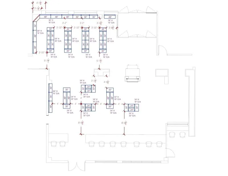
- Installation as per layout – Here installation of fixture and robots to be done as per the layout designed before.
- Trial & training at customer – here the production training/trial happens at the customer end to understand how the process works and what the sequence of the work.
- Buy off meeting – If any other thing required from customer end they raise their requirement or some modification required by the customer here all the things get discussed here.

- Final handover - here after all requirement finished from the customer end. Fixture is handover to the customer.

2.) What are the types of joining processes?
ANS.) The durability and performance of any structure is largely dependent on the quality and design of the component joints.
Whole structure cannot be made in one piece.
The two fundamental options for joining materials and components
- Metallurgical joining
- Mechanical joining
Metallurgical joining Process
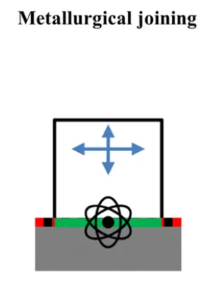
When two metals join together with metallurgical changes in it. Here parent metal or child metal gets heated up or filler material to join the components.
This process includes welding, brazing, soldering and adhesive bonding comes.
WELDING
Resistance welding
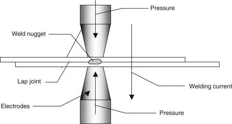
Resistance welding is a welding technology widely used in manufacturing industry for joining metal sheets and components.
The weld is made by conducting a strong current through the metal combination to heat up and finally melt the metals at localized point predetermined by the design of the electrodes and for the work-piece to be welded.
A force is always applied before, during and after the application of current to confine the contact area at the weld interfaces and in some application, to forge the work-piece.
Types of resistance welding
- Resistance spot welding
- Resistance seam welding
- Resistance projection welding
Resistance spot welding
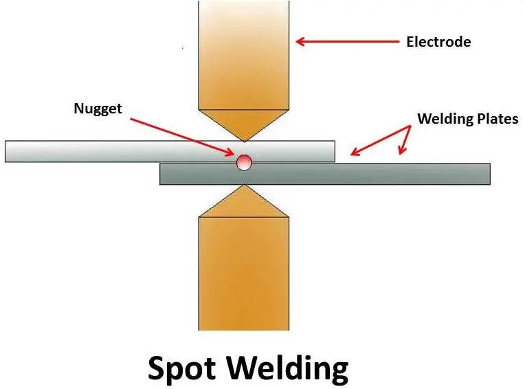
The process is used for joining sheet materials and uses shaped copper- chromium or zirconium alloy electrodes to apply pressure and convey the electrical current through the work-piece.
Heat is developed mainly at the interface between two sheets, eventually causing the material being welded to melt, forming molten pool the weld nugget.
The molten pool is contained by the pressure applied by the electrode tip and surrounding solid metal.
Advantages
- Short weld time and hence high weld speed.
- Highly adaptable to automation and robotic techniques
- Typical BIW contains 5000 weld
- Strength and durability of automobile largely depends on quality of RSW
Resistance Projection welding
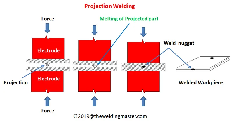
Projection welding is a resistance welding process for joining metal components or sheets with embossments by directly applying opposing forces with electrode specially designed to fit the shapes of the work-piece.
The current and the heat generation are localized by the shape of the work-piece either with the natural shape or with specially designed projection. Large deformation or collapse will occur in the projection part of the work-piece implying high.
Application
- Used for mechanical fixing of auto-body structure e.g. Weld nuts.
Resistance seam welding
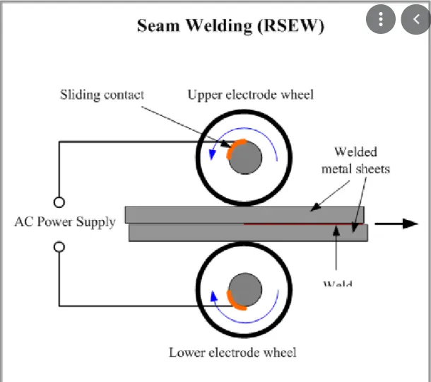
Seam welding is a resistance welding process for joining metal sheets in continuous, often leak tight, and seam joints by directly applying opposing forces with electrodes consisting of rotary wheels.
The current and the heat generation are localized by the peripheral shapes of the electrode wheel.
Application
- Seam welding is mostly applied in manufacturing of containers, radiators and heat exchanger etc.
Arc welding
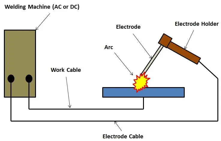
The process involves either consumable or non-consumable electrode.
An arc produced between tip of the electrode and work-piece to be welded, by use of an AC or DC power supply.
Types of arc welding
- Manual metal arc welding
- Gas –shielded metal arc welding (Metal inert gas MIG welding)
- Gas –shielded tungsten arc welding (Tungsten inert gas TIG welding)
- Submerged arc welding
- Plasma arc welding
Manual metal arc welding
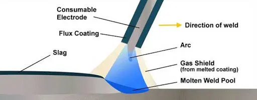
Manual metal arc welding also known as shielded metal arc welding or informally as stick welding.
Stick welding is a process where the arc is stuck between the metal rod and work-piece both the rod and work-piece surface melt to create a weld.
MIG Welding
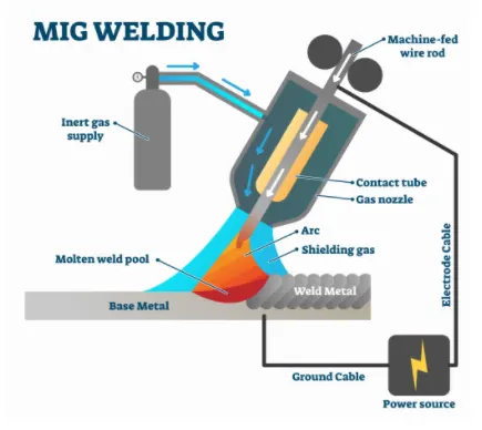
Metal inert gas welding is an arc welding technique in which a consumable electrode is used to weld two or more work-piece.
MIG welding makes use of the following components
- Consumable electrode
- Inert gas supply
- Welding head
- C or D.C power supply
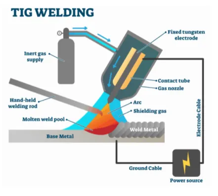
TIG Welding
Tungsten inert gas welding also known as gas tungsten arc welding, is an arc welding method that uses a non-consumable tungsten electrode to weld two or more work-piece. It is very much similar to metal to metal inert gas welding.
The following components are necessary to perform tungsten inert gas welding.
- Power supply
- Non-consumable tungsten electrode
- Inert gas supply
- Filler rod
- Welding head
Brazing
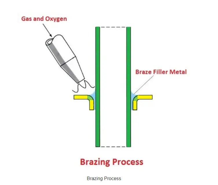
Brazing is a process of joining two pieces of metal in which a non-ferrous alloy is introduced in a liquid state between the pieces of metal to joining allowed to solidify.
The melting temperature of the filler material is about 600 C, but lower than the melting temperature of the parent metal. The filler metal is distributed between the surface by capillary action.
Soldering
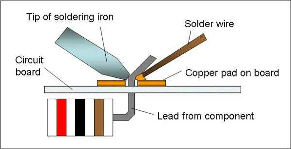
Soldering is a process in which two or more items are joined together by melting and putting a filler metal into the joint, the filler metal having a lower melting point than the adjoining metal. Unlike welding,soldering does not involve melting the work pieces.
Mechanical joining process
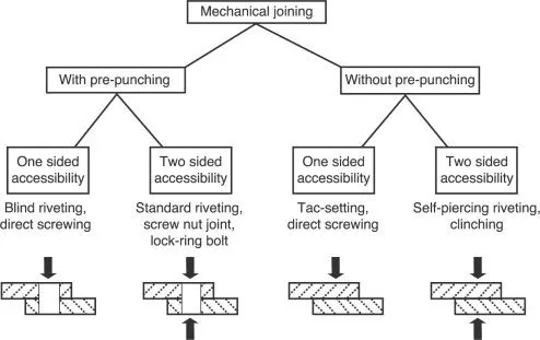
Mechanical joining- also called joining by forming- has become interesting for the automotive industry due to the request to reduce consumtion and thereby emissions.
In order to reduce weight on the car body, the usage of lightweight materials in the body-in-white application has increased.This includes aluminium,high strength steel alloys,polymers, and composites.
All mechanical joining methods are cold forming techniques. One general benefit for all mechanical joining methods is the mobility of the material after joining.
This process include riveting, self piercing riveting, clinching and hemming processes.
Mechanical joining is divided into two main groups
- Without fastener
- With fastener
Mechanical fastening
The joining of material combination which cannot be easily welded such as pre-painted steels or very dissimilar metals.
Ex. Al application in auto-body makes use of mechanical fastening techniques to overcome the poor inherent weld ability of Al.
The joining of materials in application where high fatigue life is critical compared to static strength.
The joining of materials where a long tool life of relative importance.
Screw & bolts are examples.
Self-Piercing riveting
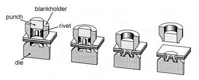
Self-piercing riveting is a high speed mechanical fastening process for point joining sheet material, typically sheets and aluminum alloys. It is a single step technique generally using a semi-tubular rivet to clinch the sheet in a mechanical joint. There is also a process variant which utilizes solid rivets.
As the name suggest pre-drilled holes are not required, allowing the joint to be made rapidly in one operation. The process cycle is shown in cross-section.
Hemming process
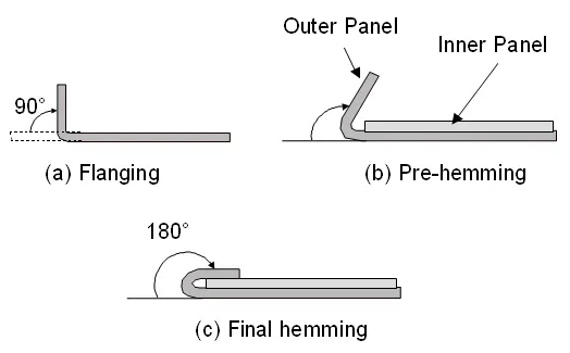
Hemming and seaming are the similar metal working processes in which a sheet metal edge is rolled over onto itself.
Hemming is a process in which the edge is rolled flush to itself, while a seam joins the edges of two materials.
Adhesive bonding
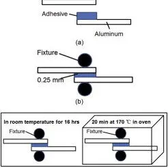
Adhesive bonding is used to fasten two surfaces together, usually producing a smooth bond.
This joining technique involves glues, epoxies or various agents that bond by evaporation of a solvent or by curing a bond agent with heat, pressure or time.
Diffusion Bonding
Diffusion bonding is a solid state joining process which is applicable to similar and dissimilar materails,primary metals,although ceramic materials can also be joined using this process. The process works through the diffusion of atoms across the joint interface at evevated temperature.
Advantages
- The bonded materials show the same physical and mechanical characteristics as the base material. The bonded surface can be tested through a tensile testing.
- Joints created by diffusion bonding are clean, of high quality,and free from discontinuity and porosity.
- Diffusion bonding allows joining similar and dissimilar materials.
- Running cost are rather low and the process is easy to approach.
Disadvantages
- Although the running cost running cost are low,the initial setup cost is high.
- Compared to other welding techniques,diffusion bonding is very time-consuming.
- The preparation of the work-pieces is critical and may be difficult.
- The available equipment limits the size of the weld.
3.) What is resistance welding & its application in the automotive sector?
ANS.) Resistance welding
Resistance welding is a welding technology widely used in manufacturing industry for joining metal sheets and components.
The weld is made by conducting a strong current through the metal combination to heat up and finally melt the metals at localized point predetermined by the design of the electrodes and for the work-piece to be welded.
A force is always applied before, during and after the application of current to confine the contact area at the weld interfaces and in some application, to forge the work-piece.
Types of resistance welding
- Resistance spot welding
- Resistance seam welding
- Resistance projection welding
Resistance spot welding
The process is used for joining sheet materials and uses shaped copper- chromium or zirconium alloy electrodes to apply pressure and convey the electrical current through the work-piece.
Heat is developed mainly at the interface between two sheets, eventually causing the material being welded to melt, forming molten pool the weld nugget.
The molten pool is contained by the pressure applied by the electrode tip and surrounding solid metal.
Advantages
- Short weld time and hence high weld speed.
- Highly adaptable to automation and robotic techniques
- Typical BIW contains 5000 weld
- Strength and durability of automobile largely depends on quality of RSW
Disadvantages
- Only thin metals can be welded accurately and efficiently.
- Installment cost is more
- This type of welding gets deformed.
- Changes in power supply leads to weak welding.
Application
- This method is used by automotive industry almost exclusively for joining steel sheet without using filler material or flux.
Resistance Projection welding
Projection welding is a resistance welding process for joining metal components or sheets with embossments by directly applying opposing forces with electrode specially designed to fit the shapes of the work-piece.
The current and the heat generation are localized by the shape of the work-piece either with the natural shape or with specially designed projection. Large deformation or collapse will occur in the projection part of the work-piece implying high.
Advantages
- The projection welding requires a very small supply of current. As less current passes through the electrode, the life of electrodes increses. This process also requires less pressure for welding.
- Unlike spot welding,there is no limitation on the thickness of metals to be welded.
- This process is suitable for automation.
- Filler material are not used in this process.hence clean joints are obtained in this process.
- This process is also effective in welding joints which are in complicated location.
Disadvantages
- Equipments are costlier.
- Projections cannot be made in thin workpiece.
- It can be applied to some type of brasses and copper.
- Projection formation in projection welding is a complicated process and it takes time. Only a skilled person can form projections of different required shape like spherical projections.
Application
- Used for mechanical fixing of auto-body structure e.g. Weld nuts.
Resistance seam welding
Seam welding is a resistance welding process for joining metal sheets in continuous, often leak tight, and seam joints by directly applying opposing forces with electrodes consisting of rotary wheels.
The current and the heat generation are localized by the peripheral shapes of the electrode wheel.
Advantages
- It can produce gas tight or liquid tight joints
- Overlap can be less than spot or projection welds
- Several parallel seams may be produced.
Disadvantages
- Cost of equipment is high as compared to spot welding set.
- Welding can done only along a straight or uniformly curved line.
- It is difficult to weld thickness greater than 3mm.
Application
- Seam welding is mostly applied in manufacturing of containers, radiators and heat exchanger etc.
4.) What is fusion welding & types of fusion welding with its application in the automotive sector?
ANS.) Fusion welding is a process in which welding is done with the help of heat to join or fuse the two or more materials into a melting point by heating them.
Here external pressure is not required to join/fuse the metals.
This method requires filler material or not.
Here faying surfaces of parent part as well as filler material melt down during welding for weld bead formation.
Advantages of fusion welding
- Filler material can be easily applied therefore large unfiiled area can be filled easily.
- No need to apply external pressure/force so primary shape of material doest matter.
- More than two components can be easily welded at a step.
Disadvantages of fusion welding
- The process is associated with distortion and residual stress generation as it involve melting and solidification.
- Heat affected zone exists in welded components. HAZ is always considered as the weak portion in welded assembly
- Mechanical properties of parent material are also severely afftected by intense heating.
- Joining dissimilar metals by fusion welding is challenging task,especially if the metals have substantially different melting point and coefficient of thermal expansion.
TYPES OF FUSION WELDING
- Fusion welding
- Arc welding
- Gas welding
- Thermite welding
- Oxy fuel welding
- Induction welding
- Pressure welding
- Diffusion welding
- Roll welding
- Friction Welding
- Forge welding
Arc welding
The process involves either consumable or non-consumable electrode.
An arc produced between tip of the electrode and work-piece to be welded, by use of an AC or DC power supply.
Types of arc welding
- Manual metal arc welding
- Gas –shielded metal arc welding (Metal inert gas MIG welding)
- Gas –shielded tungsten arc welding (Tungsten inert gas TIG welding)
- Submerged arc welding
- Plasma arc welding
Manual metal arc welding
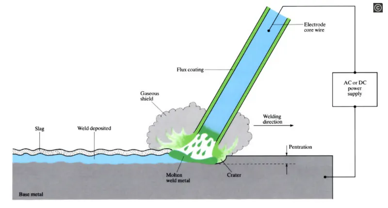
Manual metal arc welding also known as shielded metal arc welding or informally as stick welding.
Stick welding is a process where the arc is stuck between the metal rod and work-piece both the rod and work-piece surface melt to create a weld.
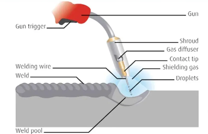
MIG Welding
Metal inert gas welding is an arc welding technique in which a consumable electrode is used to weld two or more work-piece.
This welding is used in the joining of bone,chassis area and engine parts in automotive industry.
MIG welding makes use of the following components
- Consumable electrode
- Inert gas supply
- Welding head
- A.C or D.C power supply
Advantages
- It provides higher deposition rate.
- It is faster comparing to arc welding because it supply filler material continuously.
- It produce clean weld with better quality.
- There is no slag formation.
- Minimize weld defects.
Disadvantages
- Higher initial setup cost
- Atmosphere surrounding the welding process has to be stable therefore this process is limited to draught free conditions.
- Higher maintenance costs due to extra electronic components.
- The setting of plant variables requires a high skill level.
- Radiation effects are more severe.
TIG Welding
Tungsten inert gas welding also known as gas tungsten arc welding, is an arc welding method that uses a non-consumable tungsten electrode to weld two or more work-piece. It is very much similar to metal to metal inert gas welding.
TIG welding is most commonly used to weld thin sections of stainless steel and non-ferrous metals such as aluminium BIW structures of automobile.
The following components are necessary to perform tungsten inert gas welding.
- Power supply
- Non-consumable tungsten electrode
- Inert gas supply
- Filler rod
- Welding head
Advantages
- TIG provides stronger joints compare to shield arc welding.
- The joint is more corrosion resistant and ductile.
- Wide variety of joint design can form.
- It doestn't requires flux.
- This method is well suited for thin sheets.
Disadvantages
- Metal thickness to be weld is limited about 5mm.
- It requires high skill labour.
- Initial or setup cost is high compare to arc welding.
- It is slow welding process
Submerged arc welding
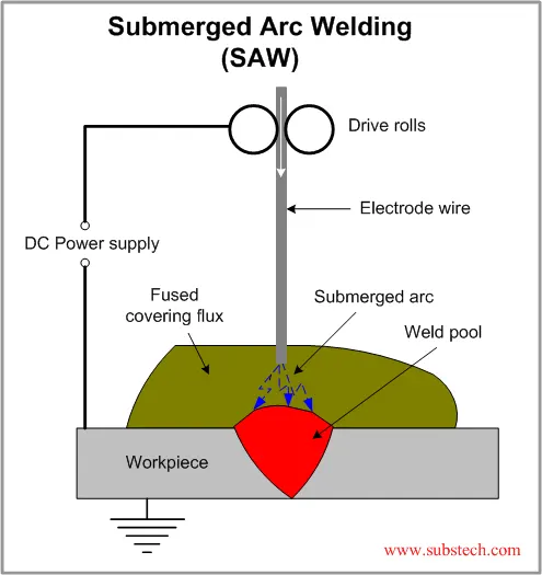
Submerged arc welding is a process in which the joining of metals is produced by heating with arc or arc between a bare metal electrode and work piece.
The arc is shielded by a blanket of granular fusible material on the work.
Pressure is not used.
Filler metal is obtained from the electrode or from supplementary welding rod.
The following components are necessary to perform Submerged arc welding
- Power source
- SAW head
- Flux handling
- Protective equipment
Advantages
- The submerged arc welding process has high deposit rate.
- In automatic application.
- very small welding smoke can be observed.
- No edge training is required.
- This method is used in indoor and outdoor.
Disadvantages
- The process is incomplete to some particular metals.
- The application is imperfect to direct seams vessels,and pipes.
- The flux usage is hard.
- A health problem can be occurred due to the flux.
- Slag elimation is desirable after welding.
Plasma arc welding
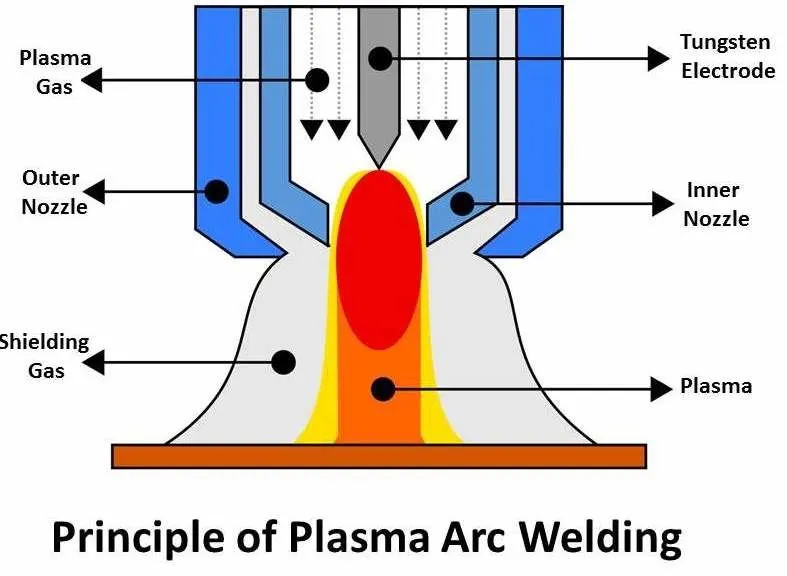
Plasma welding is very similar to TIG as the arc is formed between a pointed tungsten electrode and workpiece. however, by positioning the electrode within the body of the torch,the plasma arc can be separated from the shielding gas envelope.Plasma is then forced through a fine-bore copper nozzle which constrict the arc.
In automotive industry plasma arc welding/cutting can be used for several purposes.
The following components are necessary to perform Plasma arc welding
- Power supply
- welding torch
- water recirculator
- High-frequency unit
- Torch accessories kit
- Filler material
- Shielding gases
Advantages
- Power consumption is low
- Welding speed is high,so it can simply utilize to join thick and hard workpieces.
- Penetration rate and strong arc are high.
- It can function at little amerage.
Disadvantages
- The process is noisy.
- Equipment cost is high.
- High expertise labor required.
- Radiation is more.
5.) What is 3-2-1 principle?
ANS.) The best and most cost effective method of part location is referred to as 3-2-1 method.
The 3-2-1 principle of location (six point location principle) is used to constrain the movement of work-piece along the three axes XX,YY, and ZZ. This is achieved by proving six locating points. 3 pins in the base plate, 2 pin in verticle plane and 1 pin in a plane which is perpendicular to the first two planes.
- (3) Minimum three locator blocks to establish part plane. Three locators or supports are placed under the work piece. The three locators are usually positioned on the primary surface. This restricts one axial movement downwards and four radial movements together the three locators restrict five degrees of freedom.
- (2) Round locating pin in a round hole that defines location in four direction ( 4- way) perpendicular to the plane previously established. This restricts four axial movements.
- (1)Round locating pin in a slot that defines two of the direction of the other pin (2-way). This restricts two axial movements.
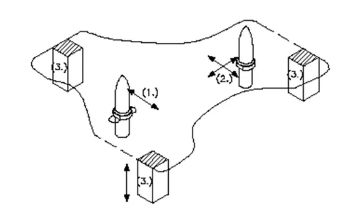
Degree of freedom controlled by 3-2-1 location principle.
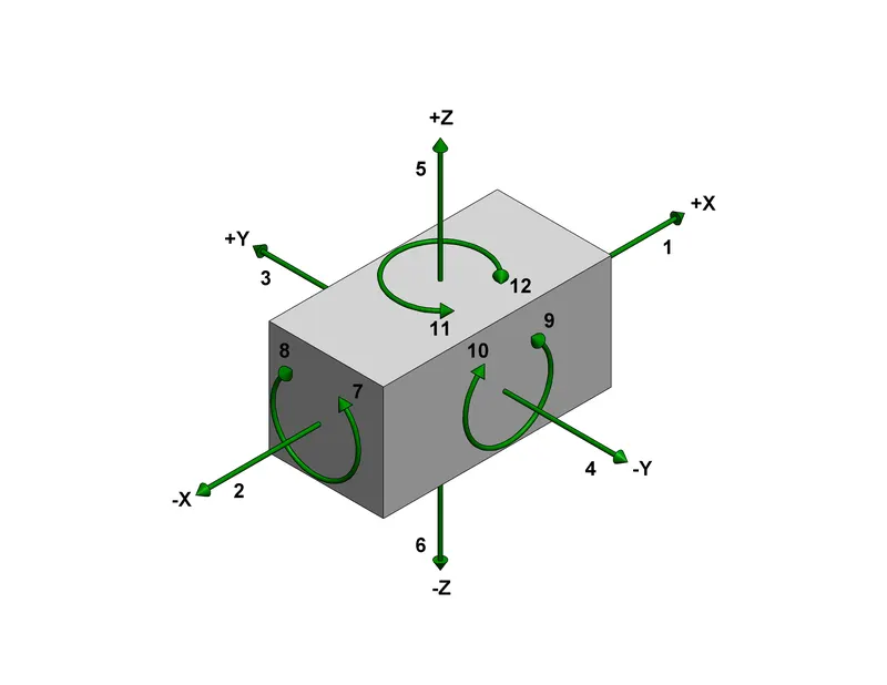
In this method,9 degree of freedom is controlled.
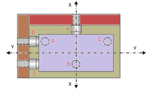
- Pins A,B,C on the base plane restrict the rotation of componenet about X axis and Y axis. It also limit the downward movement of component along Z axis. i.e. 1,2,3,4 and 5 degree of freedom is restricted.
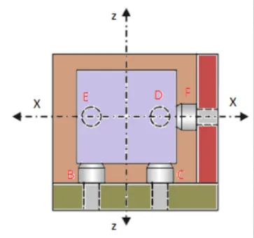
- Pin D,E is in plane parallel to the plane containing X and Z axis. It prevent the rotation of component about Z axis ( 6,7 degree of freedom) and the movement of body in Y axix towards one direction (8 degree of freedom)
- The last pin F is in plane parallel to plane contains Y and Z axis. It restrict the movement component along X axis in one direction.
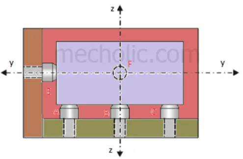
The remaining degeree of freedom 10,11 and 12 is unrestricted. It allows the loading of component in fixture. this degeree of freedom is restricted after loading of component by using clamping.
6.) Define body coordinate system?
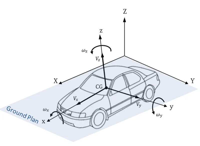
ANS.) Body coordinate system is a reference system consisting of a set of points,lines and surfaces, used to define the position of points in space in either two or three dimentions.
The body coordinate system has been widely used in the automotive industry for drawing of body parts, products and process design.
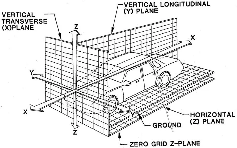
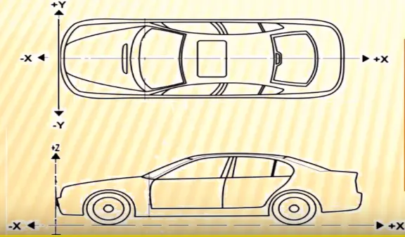
All vehicle product drawing are identified numerically relative to three vehicle planes as follows
In general BCS is also called as car line & body line.
- X = longitudinal direction FOL – Front O line or Fore/After-F/A
- Y= transverse direction COL – Centre O line or Cross car- C/C
- Z= vertical direction BOL-- bottom O line or Up & down- U/D
The origin of the body coordinate system (OX) is defined at the front center of the vehicle, it indicates a length of car and the coordinate system (OZ) is below its underbody indicates height of the car and the coordinate system (OY) its starting point is the center of the car body indicates width of car.
Maintaining X,Y and Z co-ordinates in fixture is very important factor, we should try to locate/clamp points whose points should not be in three decimal eg. X= 10.716, Y= 20.543 & Z= 30.991. It should be whole number or maximum upto one decimal.
7.) Elaborate body plane system & its essentials?
ANS.) Body planes are the reference planes in an automotive car. These planes are used to define the GD&T of all the car parts in a automotive domain.
Body planes are three mutually perpendicular imaginary planes. These are generally considered to be present at the driver position or sometimes at the engine location or at the front end of the car, depending on the customer.
The measurement from the body planes to the parts is called bodyline dimensions.
These body planes are called as
- FOL Front ‘O’ line
- COL Centre ‘O’ line
- BOL Body ‘O’ line
- The measurement along FOL or X axis is called as F/A front Aft
- The measurement along COL or Y axis is called as C/C cross car
- The measurement along BOL or Z axis is called as U/DUP Down
Bodylines are essential for the reasons stated below
- It defines the exact position of each product in the vehicle w.r.t a fixed origin.
- If ensures flawless design for assembly
- While designing lines, all the design are carried out relative to the bodyline viz. fixture, turntable etc.
- It assists in easy location of different parts in a vehicle.
- It aims in creating a standardized system.
- It assists in quality checks.