Week 2 Challenge : Surface meshing on a Pressure valve
Aim:-Surface Meshing on a Surface Valve
Topo Logy Clean Up:-
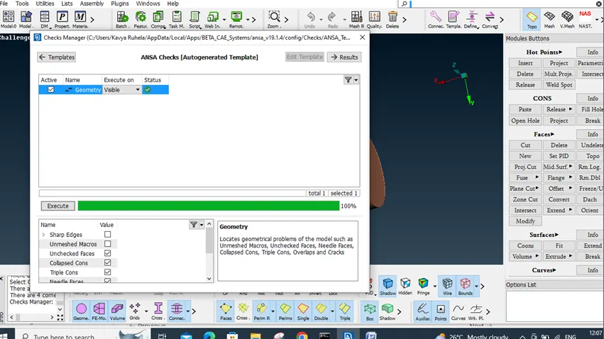
Check the Geometrical Error:- Procedure to check the Geometrical Error
Batch Section Arorrow down →Checks → Geometry Checks → Templates (ANSA Checks)→Select the geometry visible → Check the modes need to execute → Execute
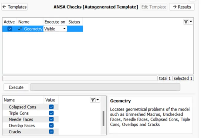
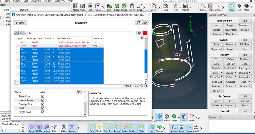
These are the shows error single cones , Double cones , Triple Cones
After the execute model shows the error. To resolve that.
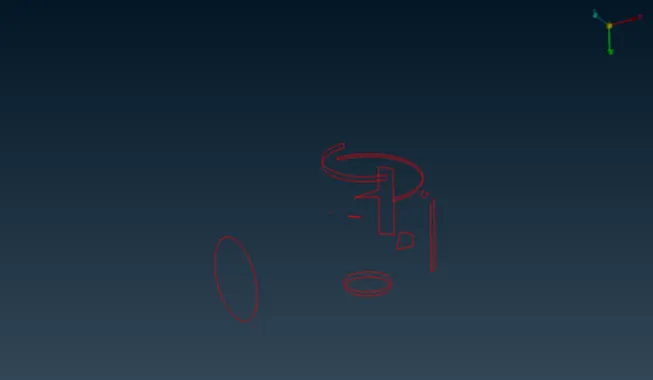
To see the wireframe single cones hides the double cone and Triple Cone & Cross Edges.
Select the CTRL+ shift to see wire frame.
In Models Single cones are presented then we needs to closed the geometry.
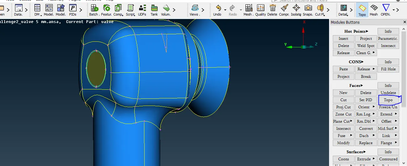
Select the TOPO Mode
Face →New(Define new face )→ Exisisting Surface
→ Planer
→ Fitted
→Cones
Choose any one as per requirement then Selected the Cones ( we can selected single entity or the loop entity)→ Centre Button Ok.→ after that we apply Topo
TOPO Selection Procedure
Select Surface → Create the Box Selection full Model→ centre button ok → its be converted into Doble
cone and Triple cones.
.
Repeate this Procedure for all single cones.
after that check the geometry check.its should be visible status ok.
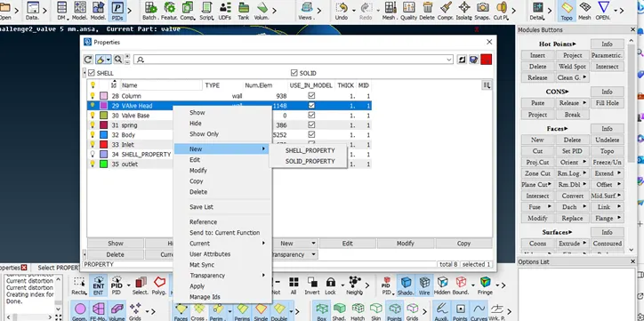
Create PID
PID Procedure
Select The
PID Mode → RightClick → New → Shell →ok
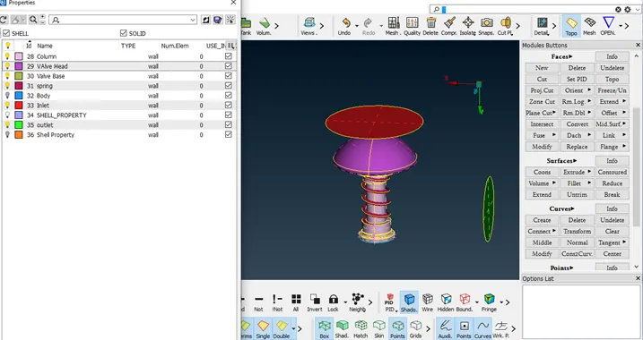
Assign the PID
Select particuular PID → Right Click → Select the entity → ok its shows the pid color.
Meshing:-
- Target length 5mm
Minimum length = 3mm
Maximum length = 7mm
Meshing Procedure
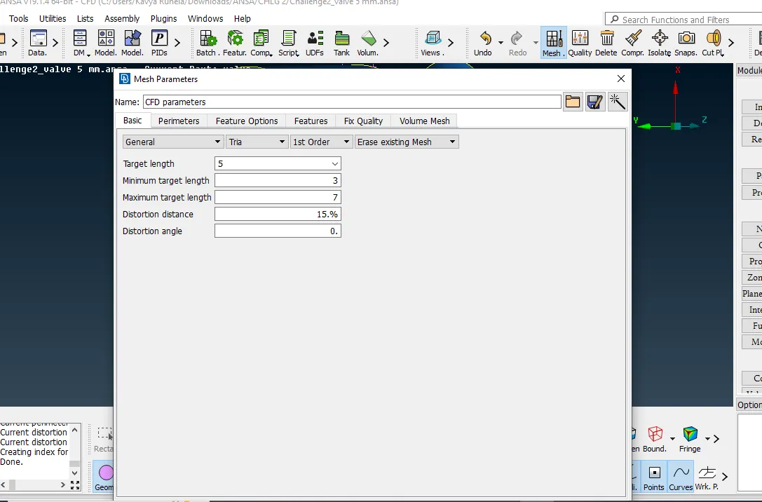
Select Mesh Parameter → Genral Select → Target Length (5mm) → Minimum Length(3mm)→ Maximum Length (7 mm) → Select Tria
Quality Parameters:-
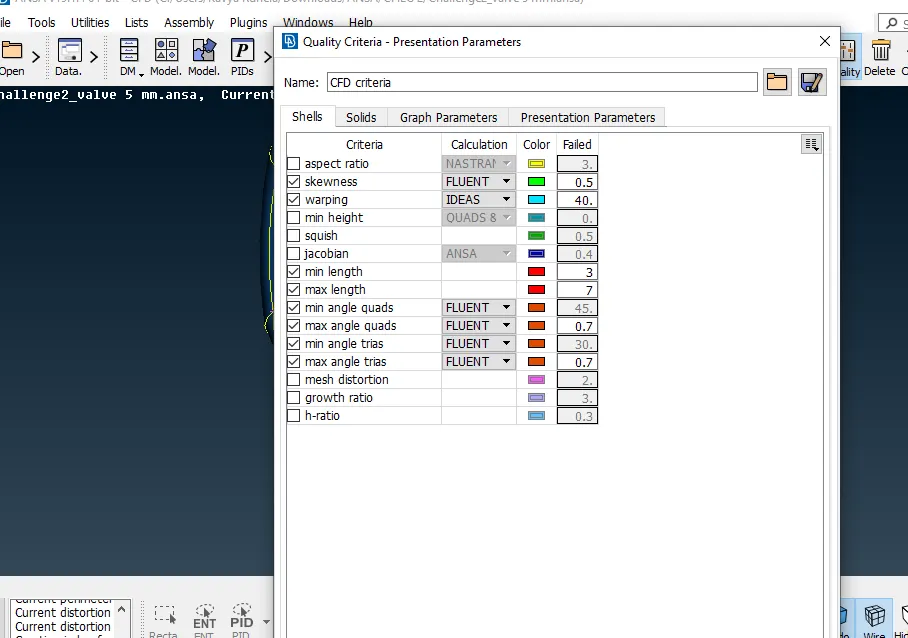
Select Quality Parameter → Minimum Length (3mm)→ Maximum Length (7mm)→ok
Length :- slection procedure
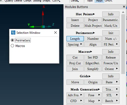
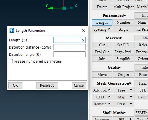
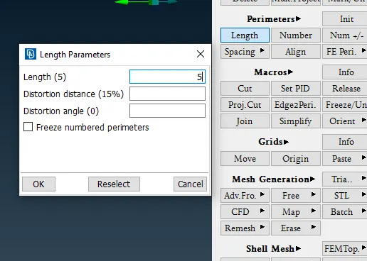
Meshing:-
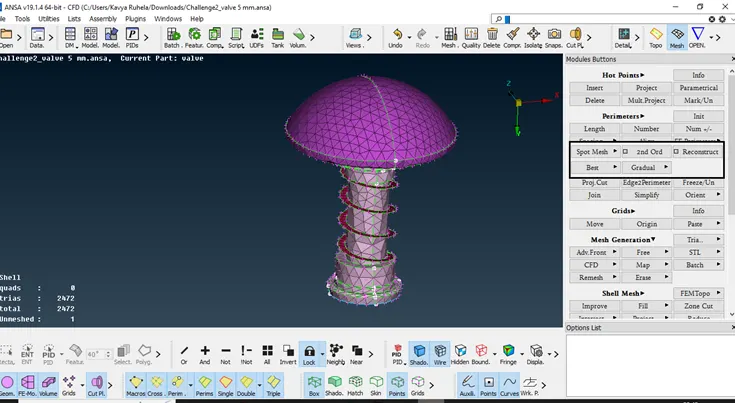
As you can see as we look into the smaller part of geometry the shape is not that sharp and accurate the spring has lost its shape completely.
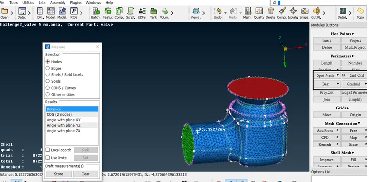
- Target length = 3mm
Minimum length = 1mm
Maximum length = 5mm
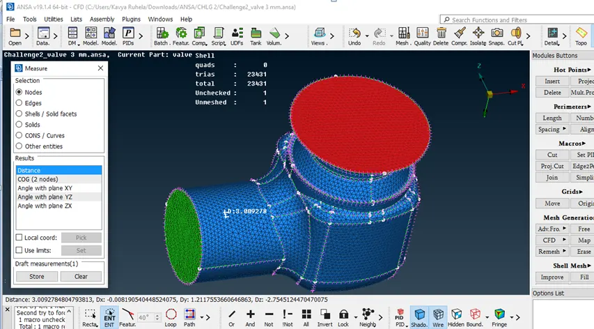
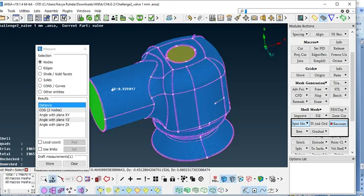
- Target length = 1mm
Minimum length = 0.5mm
Maximum length = 2.0mm
its too fine size to calulation
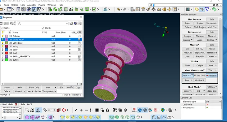
CONCLUSION:
- With fine mesh size the accuracy increases but the time for calculation also increases
- We can make two different target length according to the size of parts and required accuracy, in this case the outer casing mesh size can be 3mm which is not so large and not that fine earthier for good and accurate result
- For the smaller parts like the spring and the column head the mesh length can be 1mm so the accuracy for smaller parts increases too