Week 3 - External flow simulation over an Ahmed body.
Chlnge Ahmed Body
Q1. Describe Ahmed's body and its importance.
Ans:-The Ahmed body is a generic car body (a simplified vehicle model). The airflow around the Ahmed body captures the essential flow features around an automobile and was first defined and characterized in the experimental work of Ahmed.
Importance:-Ahmed body is a simplified car body and was first created by S.R Ahmed.This shape provides a model to study geometrical effects on the wakes of ground vehicles. This is the kind of baseline geometry for automobile bodies. The flow of air around Ahemd body captures the essential flow features around an automobile and it describes how to calculate the turbulent flow field around a simple car-loke geometry using the turbulent, flow, K-epsilon interface. People working in vehicle aerodyanamics use Ahemdbody to validate their numerical model because the experimental data for Ahemd body. Once the numerical model is validated, its is used to design new models of the car and also used for faster calculation and for comparision of analytical results.
Q2. Explain the reason for the negative pressure in the wake region.
The pressure inside the wake region remains low as the flow separates and a net pressure force (pressure drag) is produced. In other words, due to the production of pressure drag being produced from flow separation, the pressure in the wake region is low. This is what is causing the vacuum.
Q3. Explain the significance of the point of separation.
The point of separation defined by the Ahmed body and the flow, the alpha angle depending on which value is at it causes change in flow direction, forces required, lift on the body, induced drag due to “tip vortex”, at a critical value flow in slant stalls and reduced lift-reducing as well drag, all depending on the value of alfa and the Reynolds number.
open
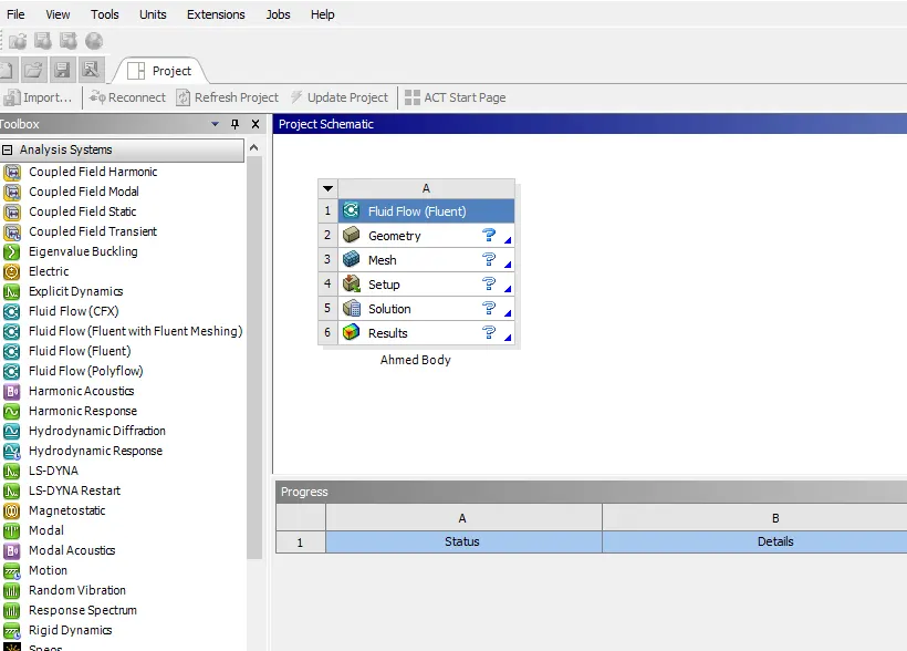
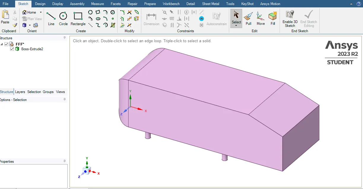
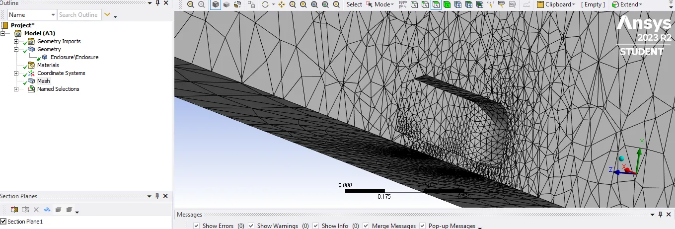
import the geometry.with New Spacicleaim.
always check the units in meters.
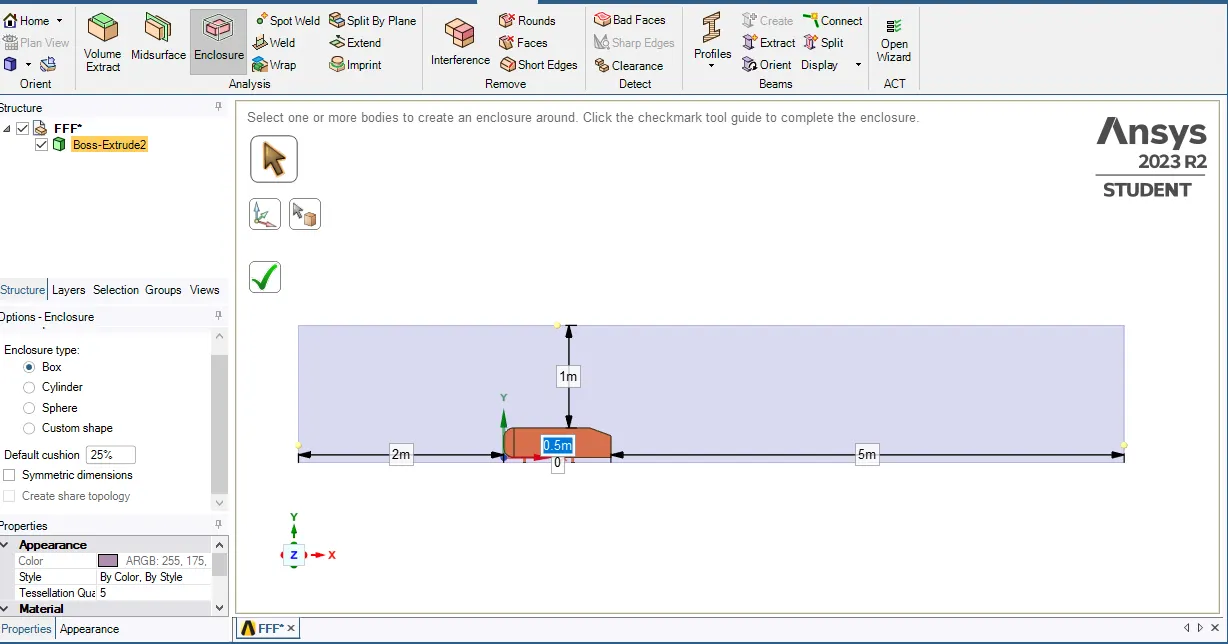
Enclose the Ahmed Body.
Prepare →Enclose → Click on Body →Give dimension front (5.0 m) →Rear (2.0m) →Bottam(0m) →Top(1m) & Widht (0.5m each)
Note for select the dimensions unchecked the symmetry option.
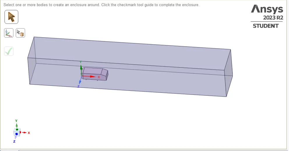
Create the volume inside that for the simulation.
Launch the setup.
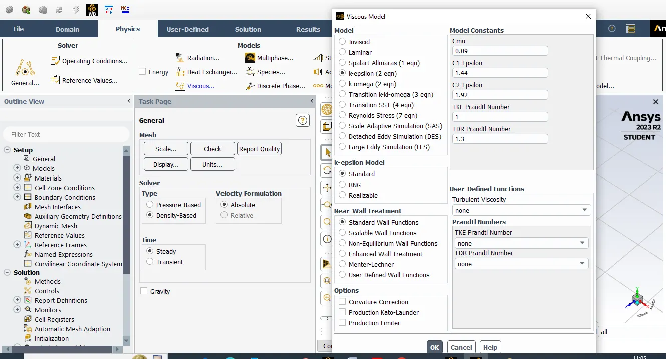
setting Domain -Desnsity Based
Viscous Model-(epsilon-2) ok & Energy turn on
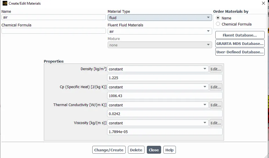
Material -Air.
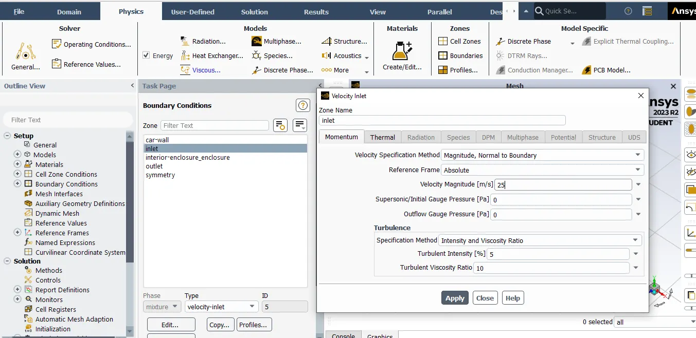
Boundary Conditions :-
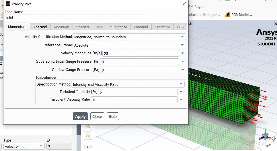
Inlet Velocity -25m/s
temp-300k
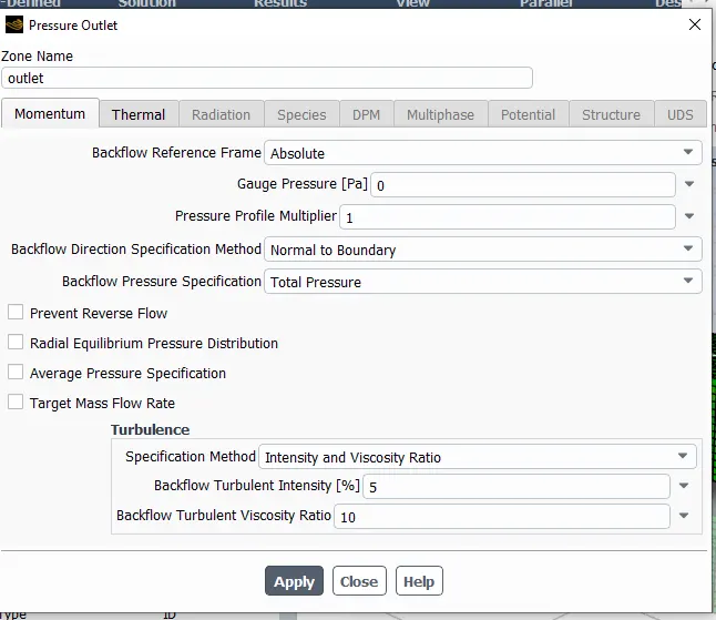
At Outlet
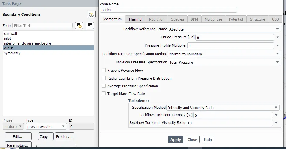
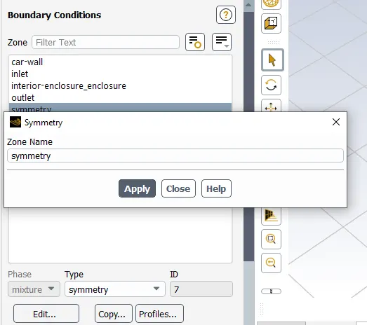
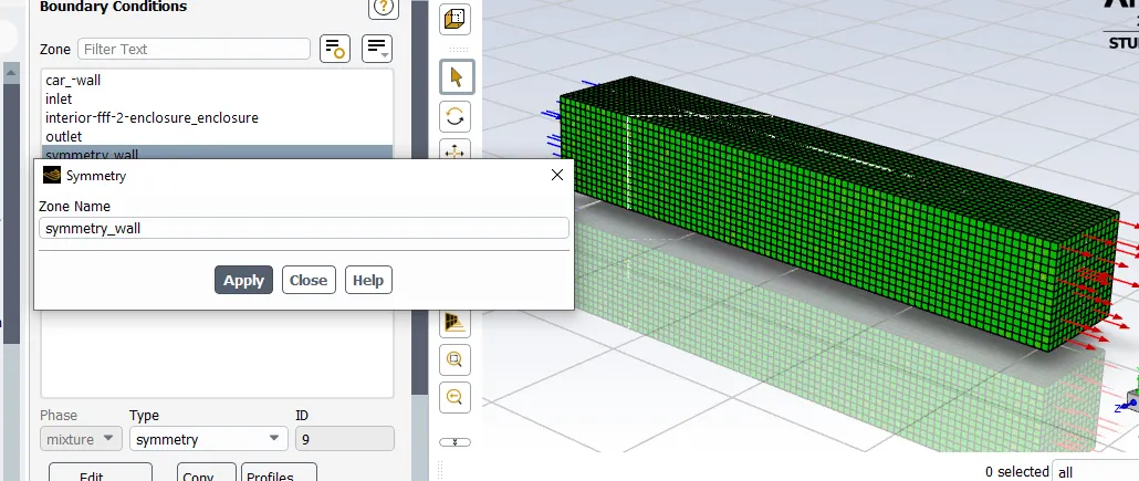
Wall
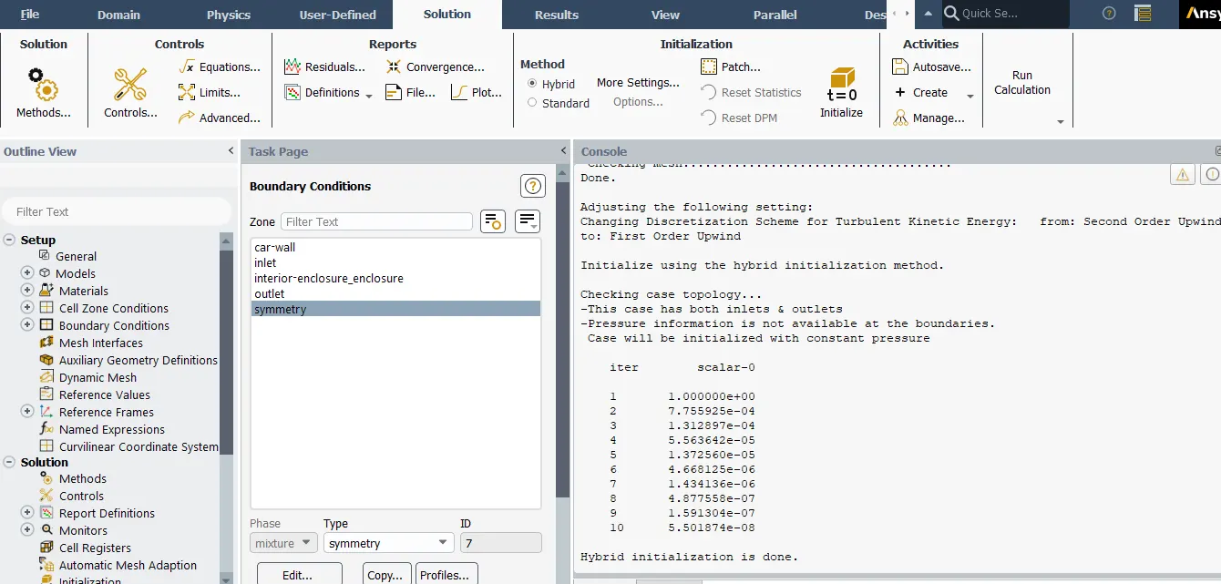
Go to the solution and Hybrid Mode & hit the Itration intlalize the eqaution.
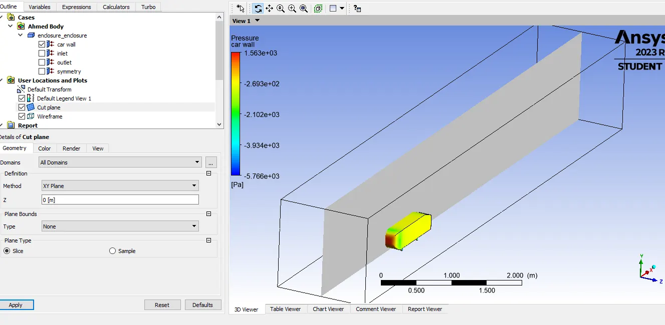
Create the Plane For Monitoring the Simulation.
If Model is X Direction the then plane must be Z direction.
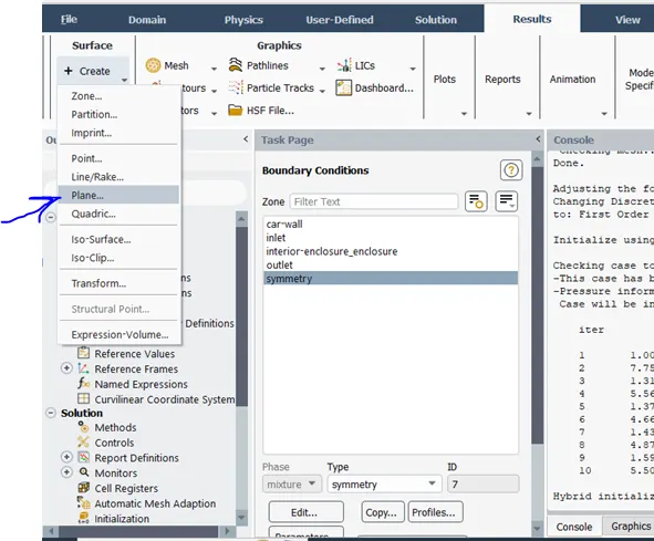
Steps to create the planes.
Result →Create → Plane →Select the orgings point & Normal and ok.
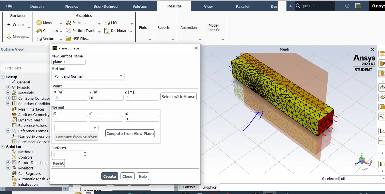
Velocity Contour.
Steps 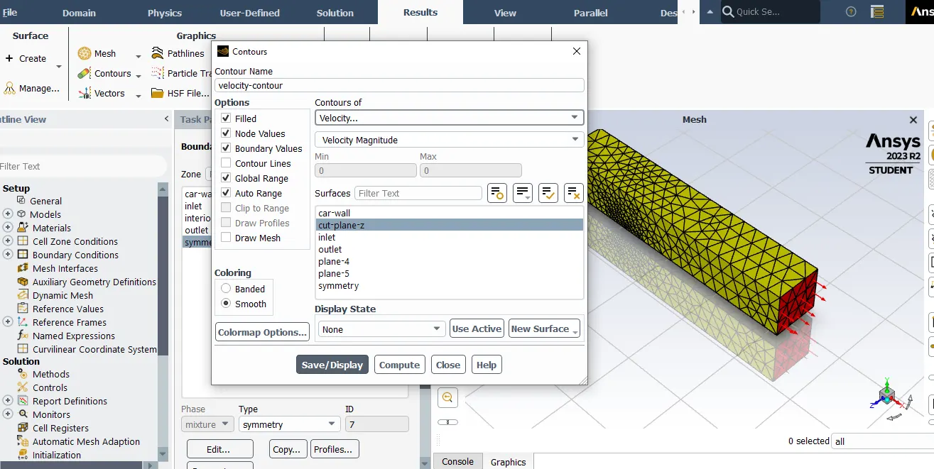
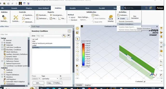
Create Velocity Animation.
Solution→Activites →Solution Animation
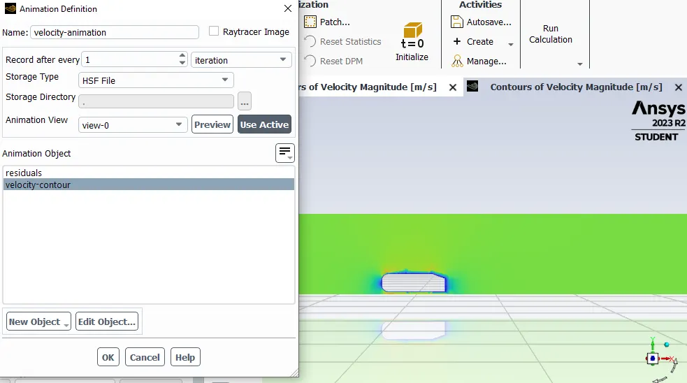
Resluts :- Prssure shows.
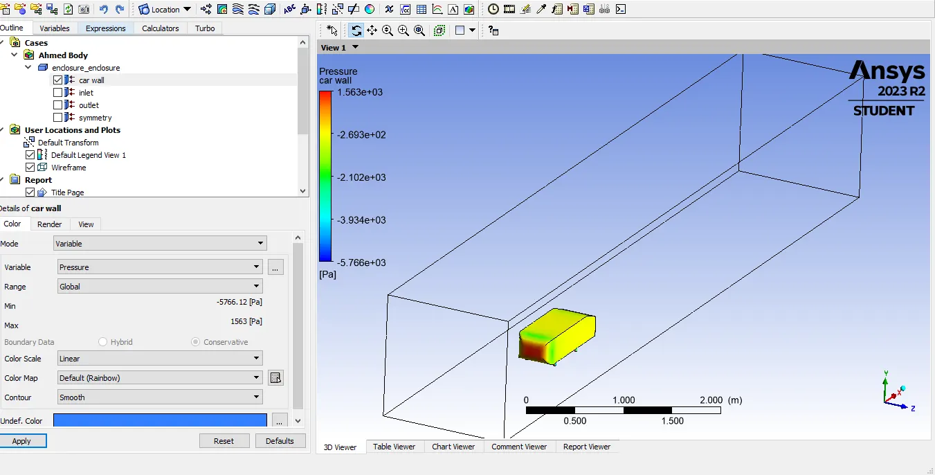
Create the plane for simulation.
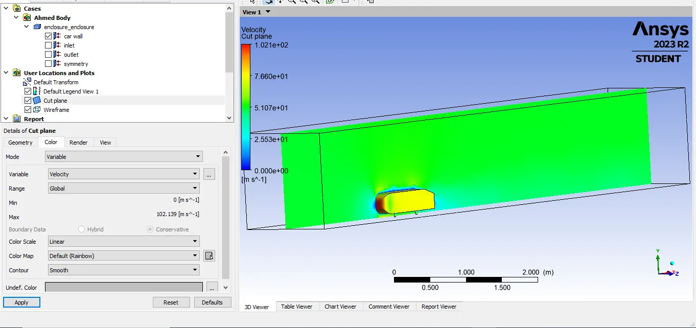
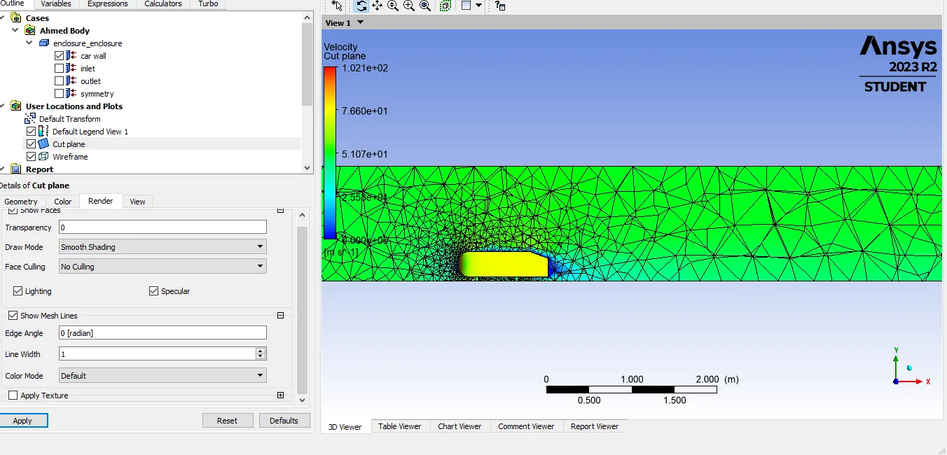
Create the Vetor
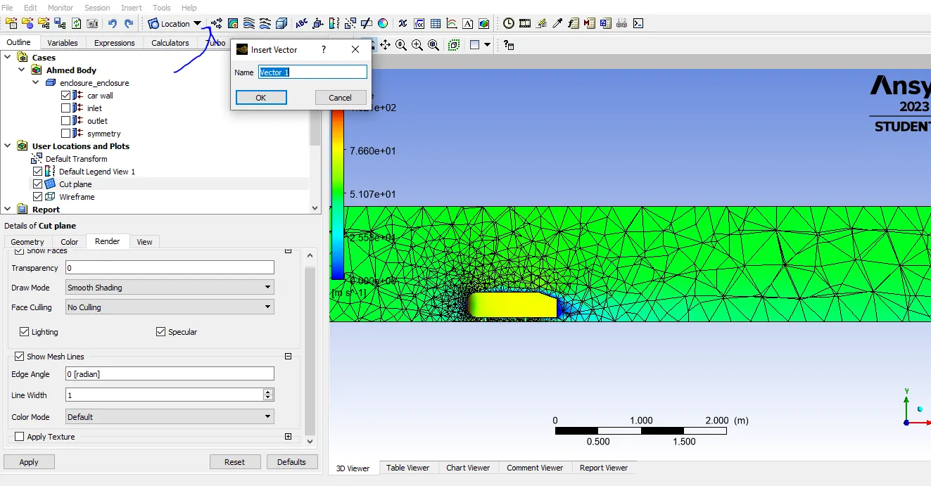
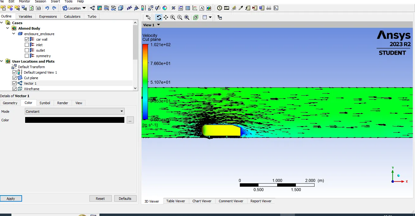
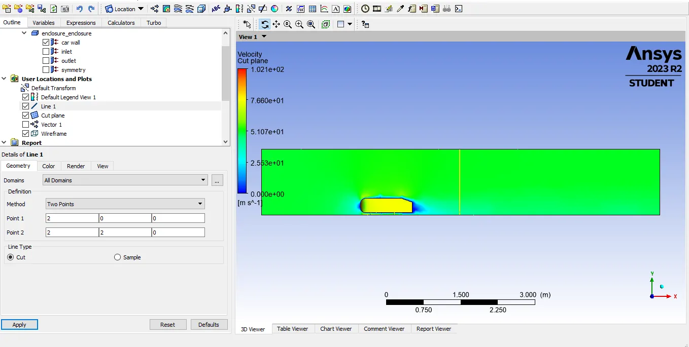
How to create a line for cut and sampling the data.
Insert→Location → Line →give the poitnts for a line.
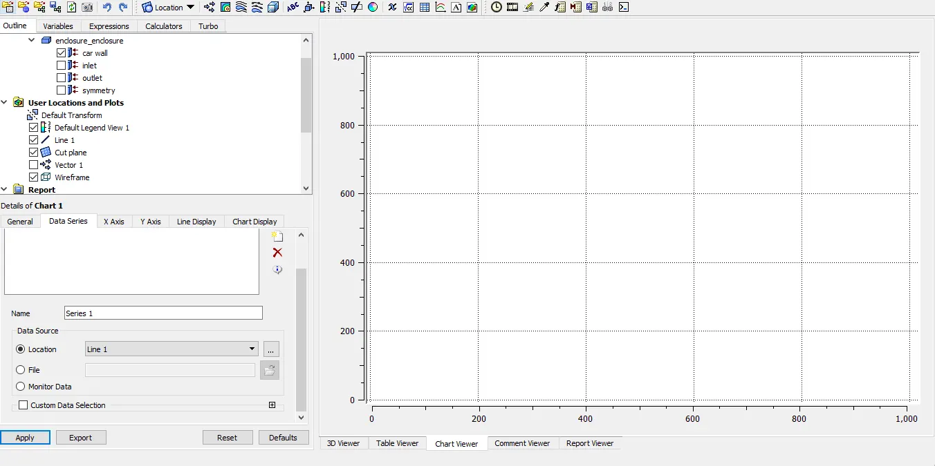
Velocity Chart :-Insert→Location → Chart →give the X axis & Yaxis parameters.
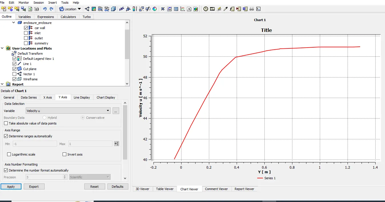
Create the duplicate line :-Right click on line -1 and recrates the same procedure.
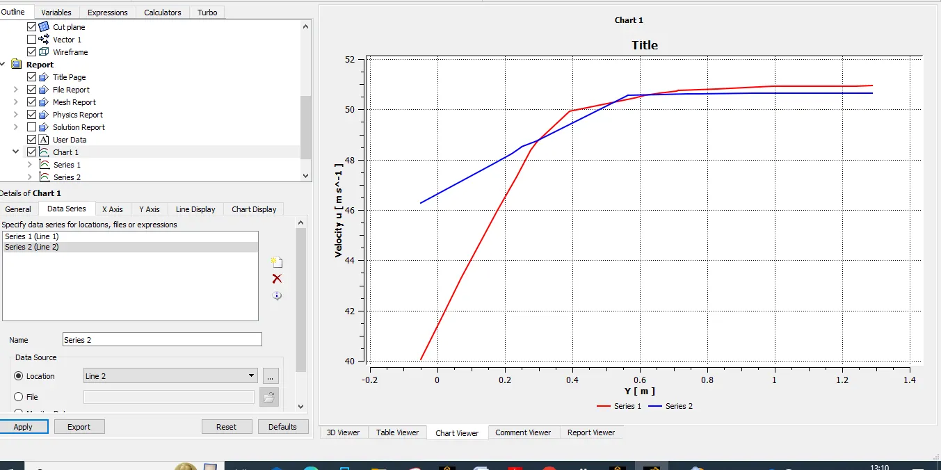
Refined Body .
Geometry & Mesh.
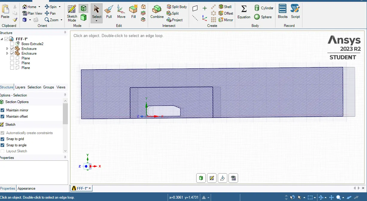
Setup Boundary Conditions.
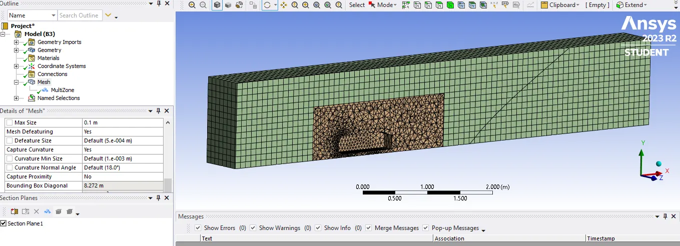
Boundary Condition.
V -25 m/s
Outlet:-
Walls
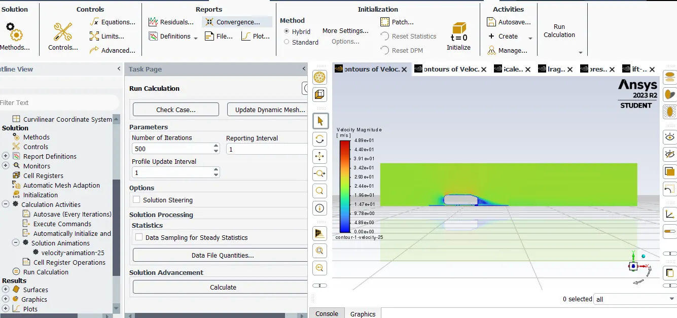
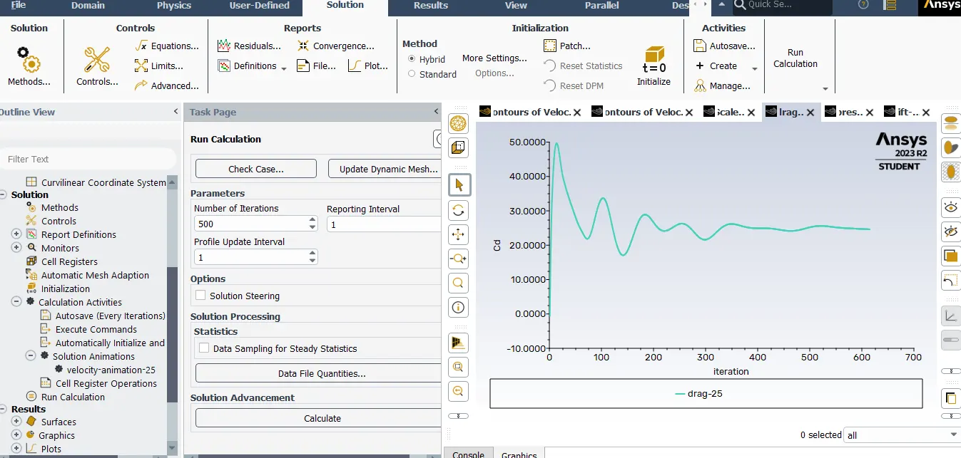
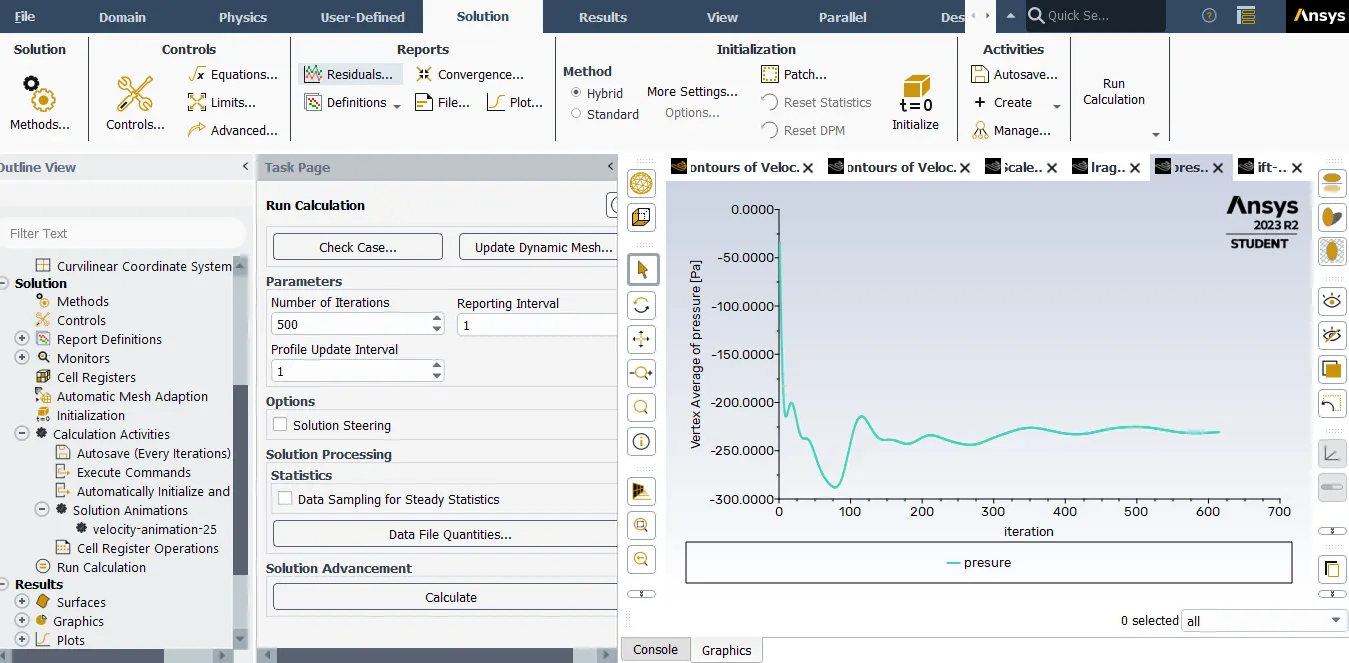
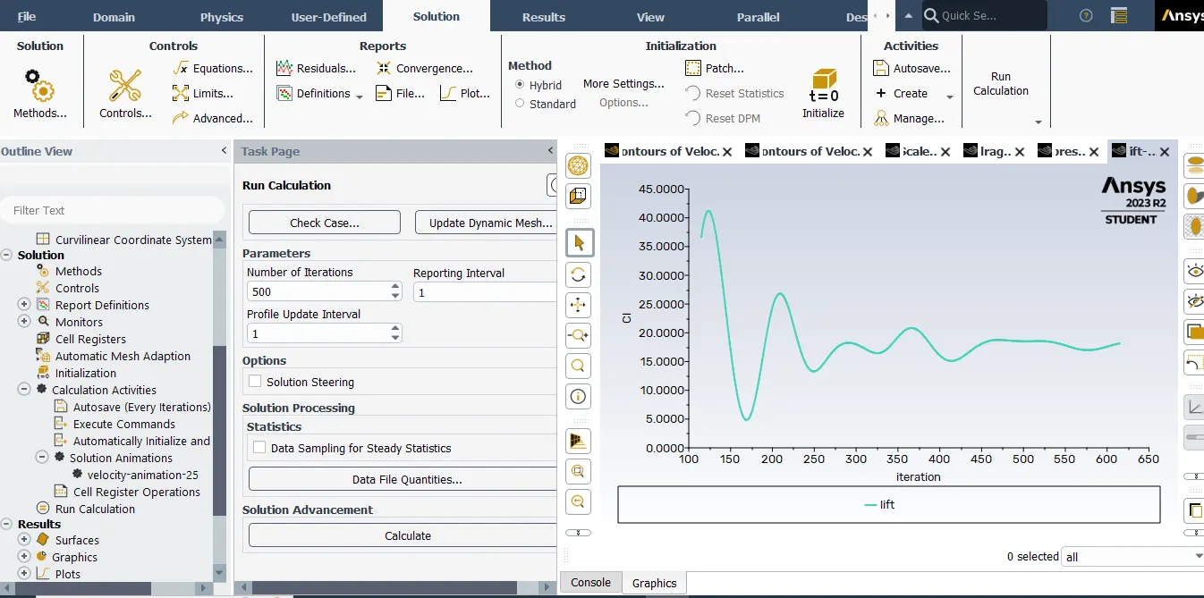
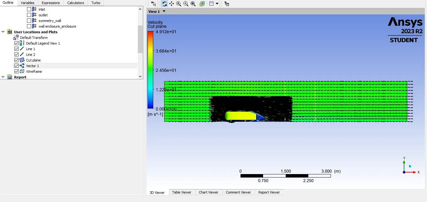
The important takeaway is that drag coeffcient does not vary significantly when the mesh is made more finer. While the drag coefficient does vary when the mesh is made more coarse. This means that the grid dependence test has passed.
Results:-
- The simulation of the Ahmed Body runs well and is in some agreement with experimental and empirical data on the body.