Week 2 Bevel Gear Challenge
Week 2 Bevel Gear Challenge
1.Aim: To perform grid dependency test for Bevel Gear Simulations for mesh sizes 4,5 and 6mm.
2.Objective:
i. To perform a grid dependency test for the Bevel gear simulation for mesh sizes 4,5 and 6mm.
ii. To solve for Von-Mises stress, Equivalent elastic strain, and Total Deformation using the previously mentioned mesh sizes.
3.Theory:
Grid Dependency Test
’Grid Independence Test’ and 'Grid Dependency Test', ‘Mesh Refinement Test’ are synonyms and they all mean the same. While performing Finite Element Analysis, one of the most common questions is finite element mesh quality. How can one know if the mesh is good enough for the analysis? Mesh density is a significant metric used to control accuracy (element type and shape also affect accuracy). Assuming no singularities are present, a high-density mesh will produce results with high accuracy. However, if a mesh is too dense, it will require a large amount of computer memory and long run times, especially for multiple-iteration runs that are typical of nonlinear and transient analyses.
The most fundamental method of checking the mesh quality is to refine a mesh until a critical result such as Equivalent stress does not change significantly with each refinement (i.e. it converges). This is the Grid dependency test, where, analysis begins with a coarse mesh and it is refined to a finer mesh for each run until the results do not change significantly and depend on the grid size anymore. As the grid or mesh size approaches zero, the approximate solution is almost equal to the actual solution. The aim of this test is to find the optimum mesh size for the solution, where it is neither too coarse to produce inaccurate results, nor where it will consume a lot of computing effort and time.
There are different mesh refinement techniques are used which have advantages and disadvantages and some depend on the experience and technical expertise of the FEA analyst. These techniques include- Reducing the element size, Increasing the element order, Global Adaptive mesh refinement, local adaptive mesh refinement, manually adjusting the mesh, Time adaptive mesh refinement, wavelength adaptive mesh refinement, etc.
4.Procedure:
In this challenge, we will be carrying out Static Structural Analysis on a pair of Bevel Gears with 3 different mesh sizes, i.e., 4mm,5mm and 6mm.
- Open the ANSYS Workbench software. Under the Analysis system select the Static structural and wait for few seconds to pop up the window, which contains Engineering data, Geometry, Model, setup, Solution and Results.
- Rename the static structural as Bevel Gear.
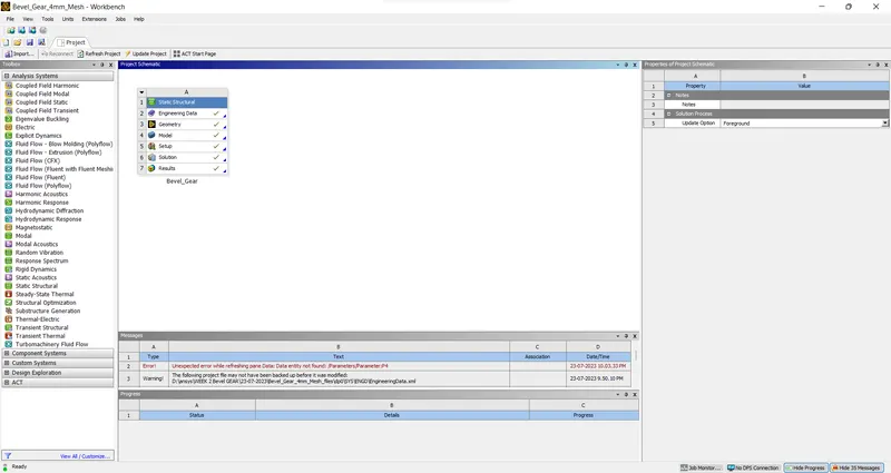
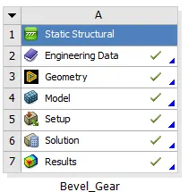
- Update the required material to the system, under the Engineering data. Here we are using "Structural Steel".
- Import the given geometry into design modeller/ Spaceclaim and remove the unwanted surface for this stimulation using "Pull" option because it will increase our solving time.
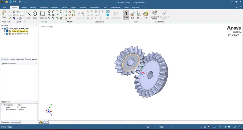
Figure: Model imported in Spaceclaim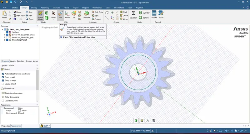
Figure:Pull option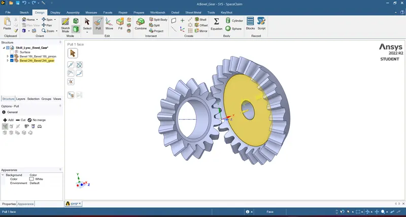
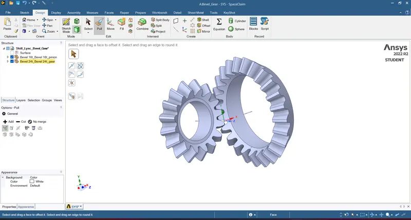
Figure:Pulling out the unwanted geometry - Open the Geometry in Ansys Mechanical.
- Now we need to define contact between the pair of bevel gears. For this we use Frictional Contact with the following details:
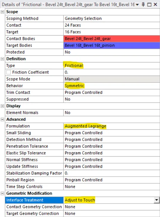
Figure: Contact details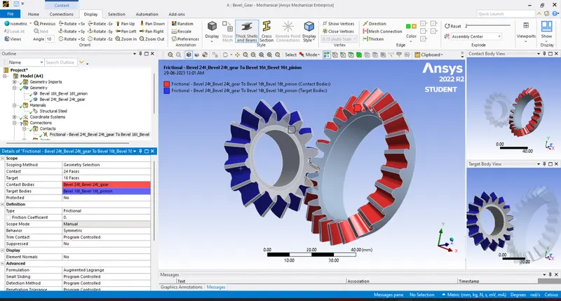
Select Contact type = Frictional. Because due to friction, there will be movement between gears.
Select Behavior = Symmetric
Select Formulation = Augmented Lagrange. As soon as teeth come in contact, it will tend to move from its position. So, Augmented Lagrange formulation reduces vibration and penetration and increases stiffness of gears.
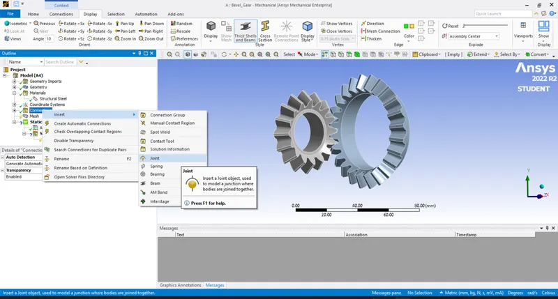
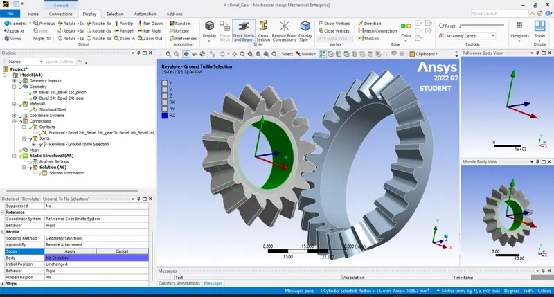
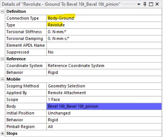
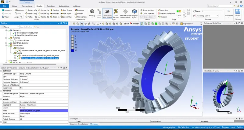
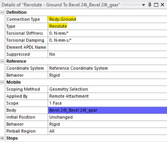
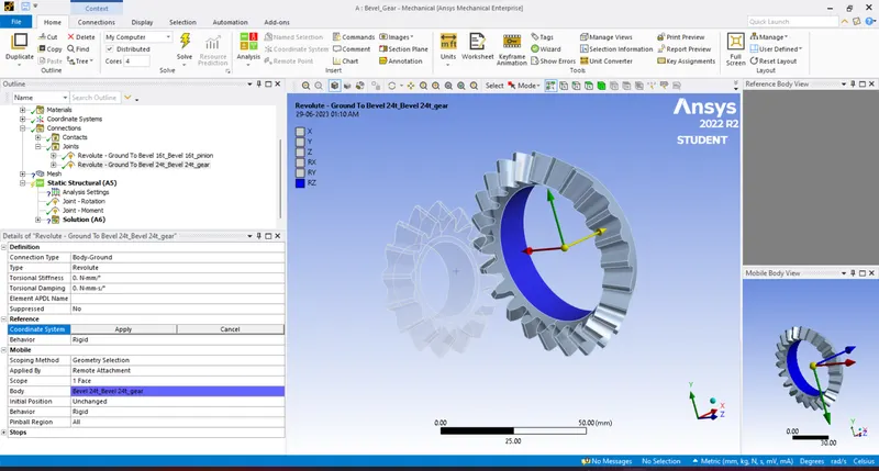
Select Interface Treatment = Adjust to Touch. Because if there is a gap between them or initial penetration, then this setting will help to adjust it and any error can be avoided. - After creation of connection between gears, create joints. Select inner face of each gear and give it a Revolute Joint as described in the image.For frame of reference for gears, select Connection Type = Body to Ground for both of the gears.We can see that in revolute joint, degree of freedom for gears automatically set to its axis or in RZ direction.
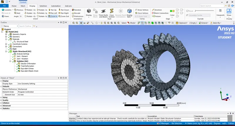
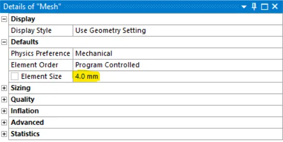
- Meshing: Create a 2D mixed mesh using mesh size 4mm.
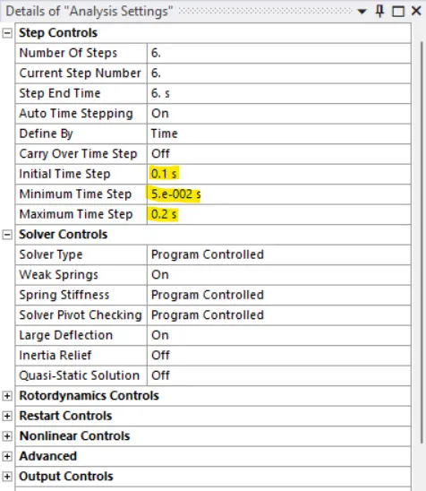
- Boundary conditions: Here we are going to look at contact forces, traces and stress developed for 1 revolution of gear. So for 180 degree angle , In analysis settings give values as given below:
No. of Steps = 6
Auto Time stepping = ON
Defined by = Time
Initial Time Step = 0.1
Minimum Time Step = 0.05 s
Maximum Time Step = 0.2 s
Select all 6 steps and select “Large Deflection = ON” in solver controls.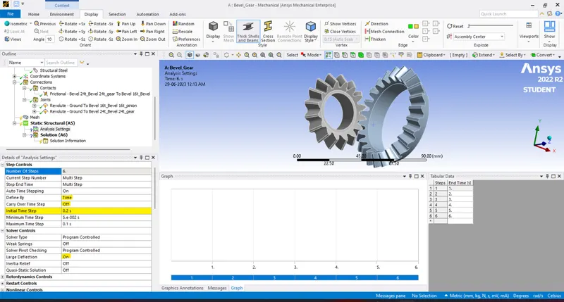
Other Boundary conditions for joints are as given below:
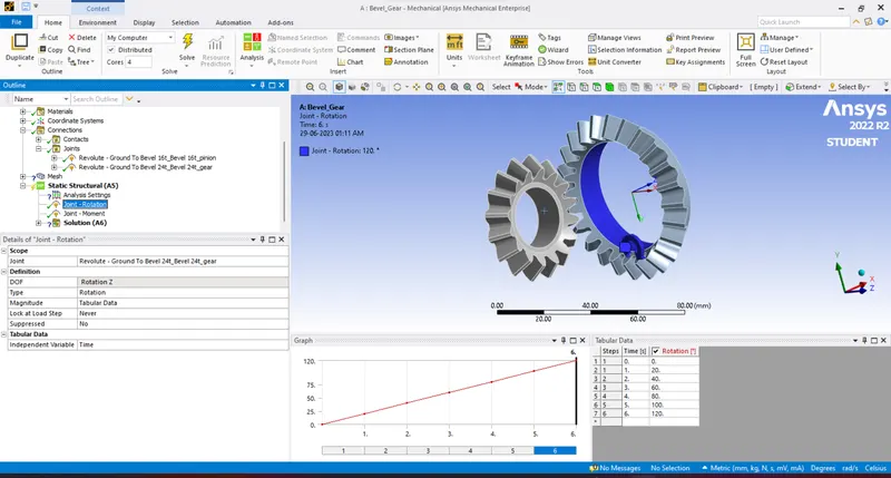
Joint Load :
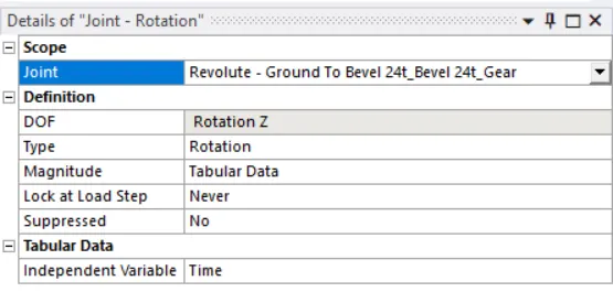
Joint: Revolute - Ground To Bevel 24t_Bevel 24t_GearType: Rotation
Magnitude: Tabular Data
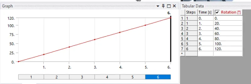
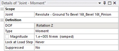
For pionion(driver), we give the Type as Moment.
Joint Load :
Joint: Revolute - Ground To Bevel 16t_Bevel 16t_PinionType: Moment
Magnitude: Tabular Data
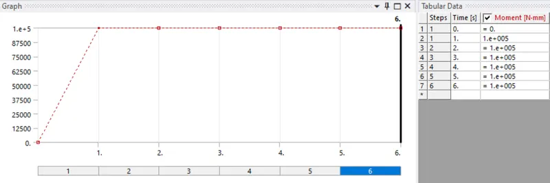
We can change the direction of rotation of the gears by clicking on the respective local coordinate system to ensure that both are rotating in opposite directions.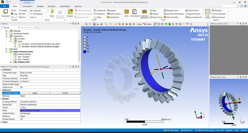
- Solution:After giving proper boundary conditions, create desired solutions for output results.
Create Solutions for “Equivalent (Von Mises) Stress", “Equivalent (Von Mises) Strain",“Total Deformation”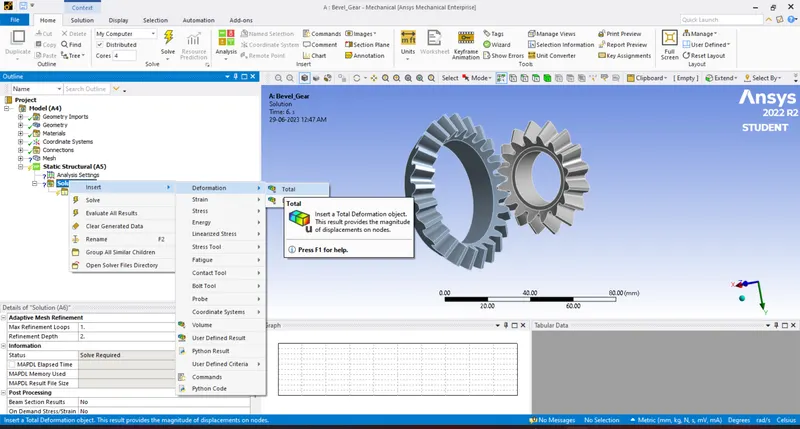
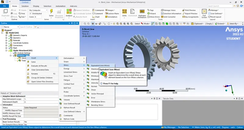
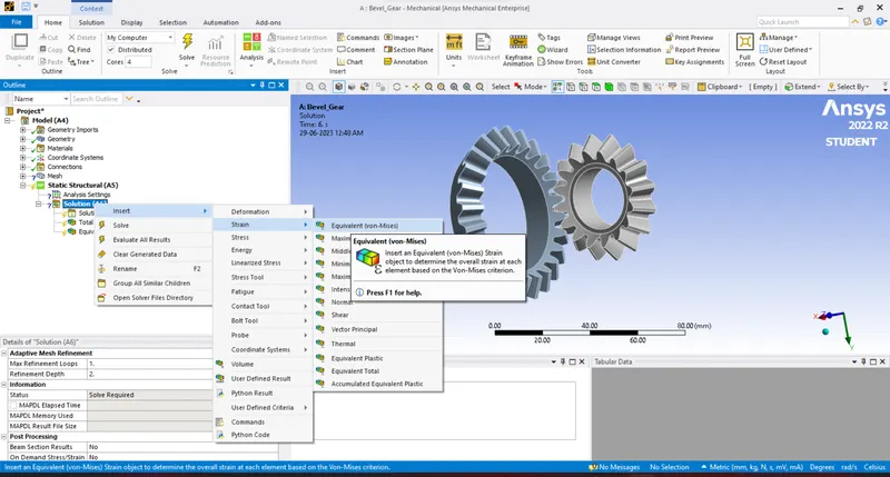
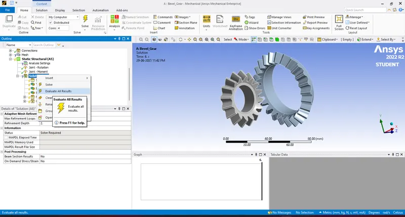
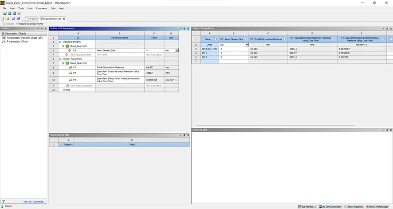
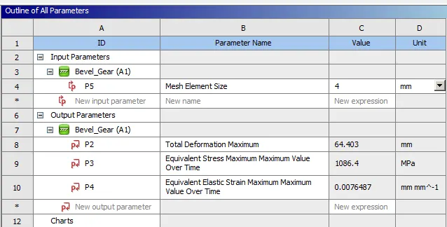
Post this we have to repeat these procedures for 5mm and 6mm mesh. Or another approach is where we can define input and output parameters and carryout the analysis at once.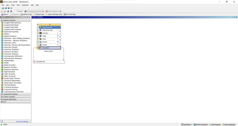
5.Results and Observations:
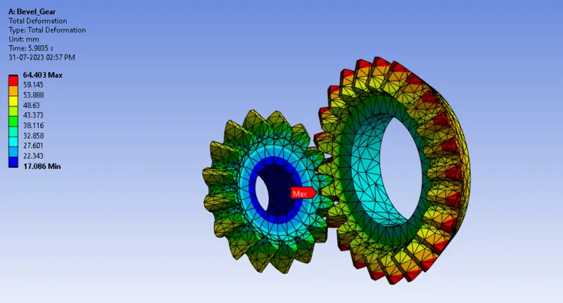
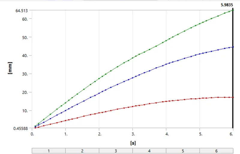
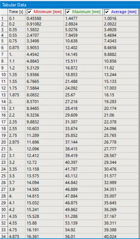
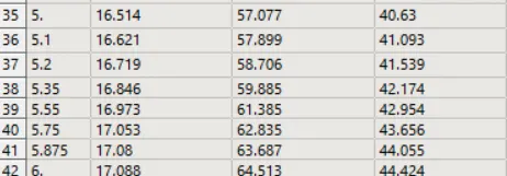
5.1 Total Deformation(4mm Mesh):
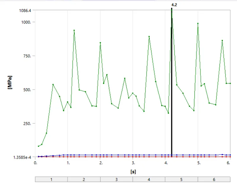
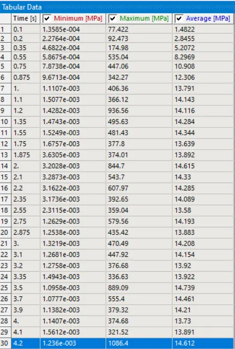
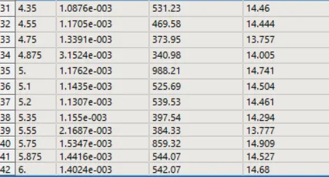
5.2 Equivalent stress distribution(4mm Mesh):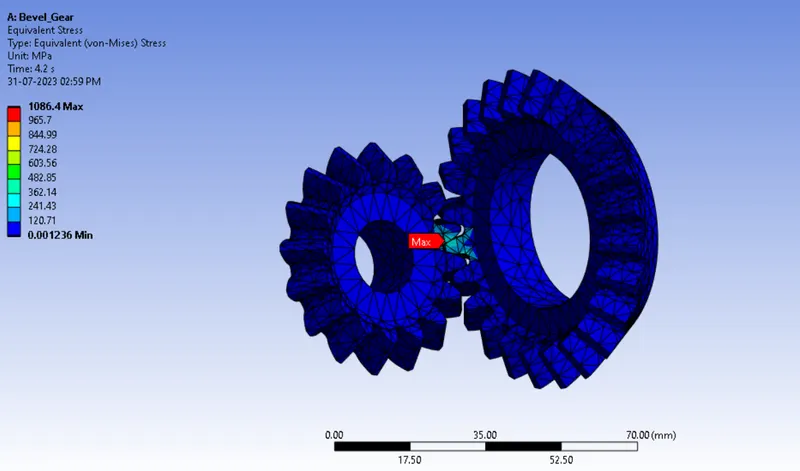
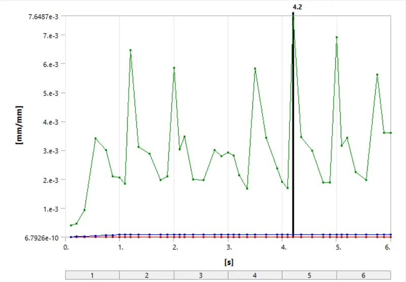
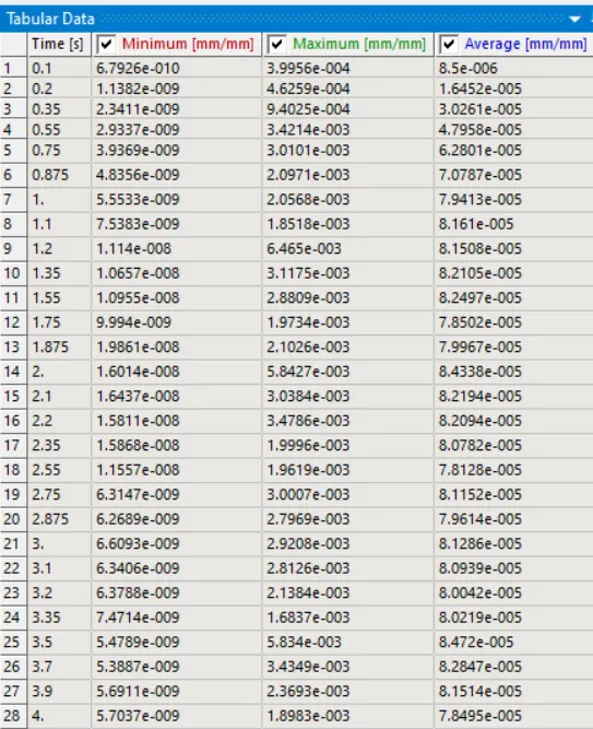
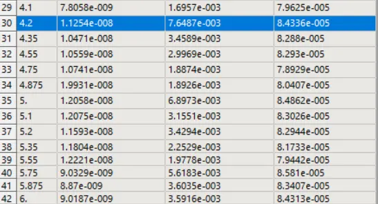
5.3 Equivalent strain distribution(4mm Mesh):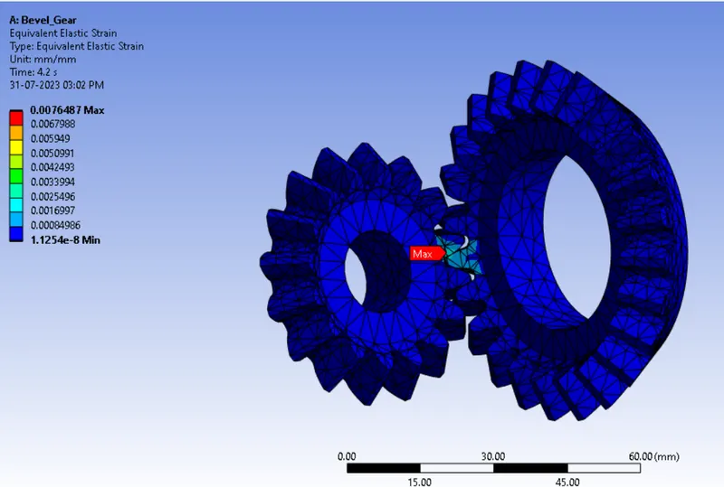
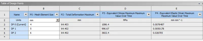
The results for 5mm and 6mm mesh are shown in parameter set as given below:
6.Conclusions:
1.From the above results, it can be observed that for all the three mesh sizes, total deformtion remained same, i.e, 64.40mm.
2.For fine mesh, say 4mm, the stress and strain results seem to be pretty much accurate but as we increase the mesh size to 5mm the stress- strain values reduced which was expected. Above 5mm size the mesh became too coarse that the results seem to be unrealistic.
3.The takeaway is that 4mm mesh gives us more accurate results but at the cost of more computational power and time. 5mm mesh reduce computational power and time but we have to compromise a little bit on accuracy. Finally for a size of 6mm the mesh becomes too coarse that we won't be getting realistic results.
4.This is called "Grid Dependency Test" by which we select the optimum element size for pre-processing taking into consideration Accuracy of Results, Computational Power and Time.