Week 3 - 2D meshing for sheet metal
2D MESHING OF HOOD
1.Aim: To extract the midsurface of given sheetmetal component(Hood) and mesh it as per the mentioned quality criteria using ANSA.
2.Objective:
- To extract the midsurface of each of the four subcomponents[Inner extract,Outer extract,Latch reinforcement extract and Hinge reinforcement extract] of the hood separately after checking the geometrical errors.
- To mesh the midsurfaces as per the given quality criteria:
S.No
Quality Criteria
Value
1
Target/Average length
5
2
Minimum Length
2
3
Maximum Length
7
4
Aspect
3
5
Warpage
15
6
Skewness
45
7
Jacobian
0.7
8
Minimum Quad Angle
45
9
Maximum Quad Angle
135
10
Minimum Tria Angle
30
11
Maximum Tria Angle
120
10
Tria Percentage
15
- To ensure that features in the model are captured properly with good mesh flow.
3.Theory:
Engine cover or Engine hood is the most eye-catching body component and important opening piece to the body, which directly affects the overall performance and comfort. Front cover assembly not only plays an important role in air guiding, but also protects the engine and surrounding pipeline accessories, meanwhile it can sufficiently avoid impact, corrosion, rainwater and electric interference.
The following are the design consideration involved in the Design of Engine Hood.
- Pedestrian Safety:Pedestrian safety always a factor involved in the design of the hood. This is achieved by proper selection of material that can readily deform avoiding risk during impact, Providing embosses to inner panels, etc. This is one of the major factors for a vehicle to have better safety ratings.
- Vehicle Quality:This involves how best the hood can be designed to have better quality in terms of Torsional stiffness, dent resistance(Hailstone and stone chippings), Corrosion resistance better weight distribution, and noise attenuation.
- Occupant Safety:The design consideration must include the impact caused due to Frontal Crash Collapse. Such Scenario is expected that Hood maintains its Integrity with hinges and also retain any of loosed components from Engine Compartments.
- Styling:Better Surface quality (A-class Surface Finishing), Tight radii on hemmed panel edges & low strain between curved regions of the inner and outer panel.
- Manufacturability:The design should be always considered for manufacturability e.g. Embossing on the inner Panel should have sufficient draft angles provided for the Punching tool to flowin and flow-out. Any Design should be studied for Manufacturability in order to produce it.
Material selection for automotive closures is influenced by different factors such as cost, weight and structural performance.The commonly used materials are Steel and Aluminium.
4.Procedure:
Step 1: Importing the geometry
- First step is to import the geometry into ANSA software.We can do this by either of the two options:
- File → open → select the file in supported format → open or
- Simply drag and drop the file in required format into ANSA.
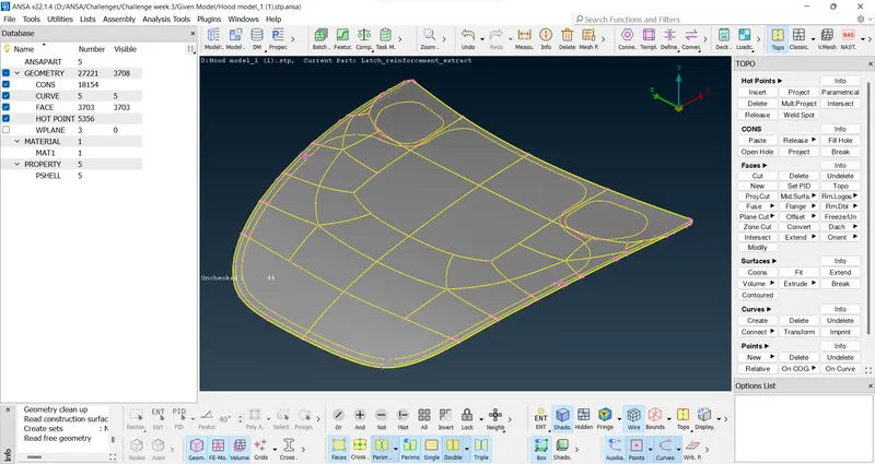
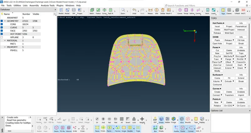
Figure: CAD Model
- There are four components in the imported model namely Inner extract,Outer extract,Latch reinforcement extract and Hinge reinforcement extract. We approach them separately with the same procedure.
Step -2: Geometry cleanup
- Cons resolution: We have to do the cons resolution to check the actual shape of the cons in the geometry. There are two tools for this. One is 'Fine' option in Auxilaries group under the Topo module. The other one is 'Length' option in Perimeters group under the Mesh module. The 'Length' tool helps to do this in a single step when compared to fine tool.
Mesh module → Perimeters → Length → Perimeter/macros (do this for both) → select the whole surface → middle mouse click → give the value as 1 → apply.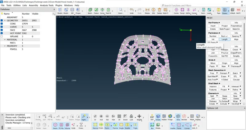
Figure: Selecting Length option from Perimeters group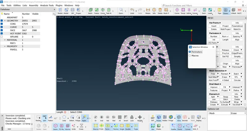
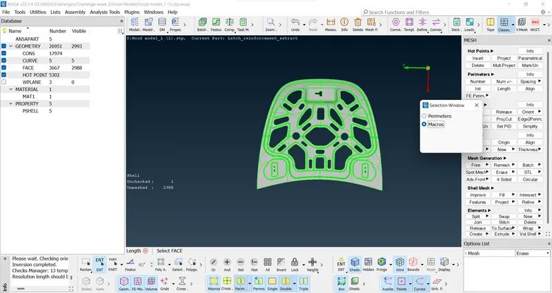
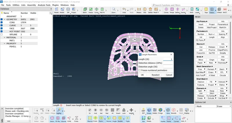
Figure: Assigning Perimeter and Macros values as 1
- Connectivity correction: There may be surfaces without connection in the imported model (Single cons). If present, we have to correct them using the 'Topo' option in Faces group under the TOPO module.
Topo module → Faces → Topo → select the whole surface at once → Apply (Middle mouse click).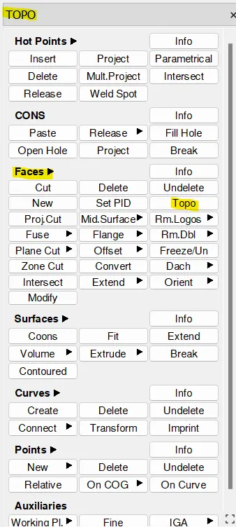
After performing Topo, we can see that all the single cons(red) will be converted to double cons(Yellow).
However, no connectivity issues were present in our model. - Orientation correction: Sometimes, the given model is observed with yellow and grey color surfaces mixed together when viewed under ENT mode. This indicates mixed normal direction among the surfaces. We have to correct the visible surfaces to either gray(+ve) or yellow(-ve), preferably gray. The tool, 'Orient' is used for this purpose.
TOPO module → Faces → Orient → Choose Select, Visible or Auto appropriately.
If cone correction is done properly, choosing the visible option will change the colour of entire surfaces in one go.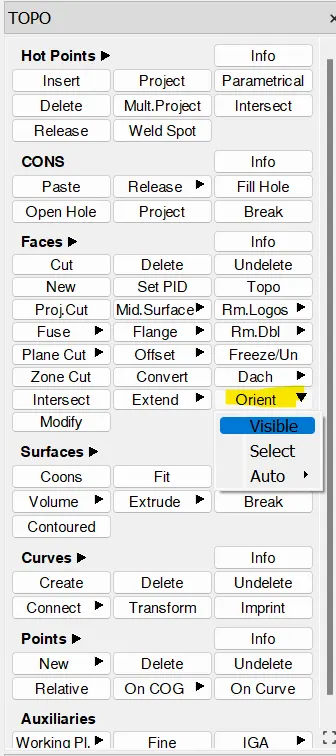
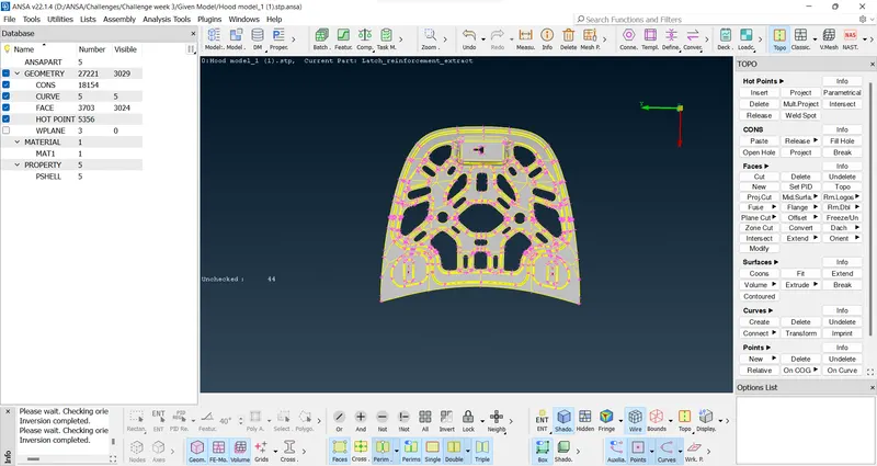
Figure: Orientation correction for Inner extract
- Geometry check: We need to check the geometry by using 'Geometry' option to find and correct any other errors in the imported geometry.
Tool tab → Checks → Geometry → Tick the single cons as well → Execute → If any errors pop up in red color select all of them at once → right mouse click → Fix → If not fixed, try manually → Then execute the geometry check again, it will show No errors or warning exist.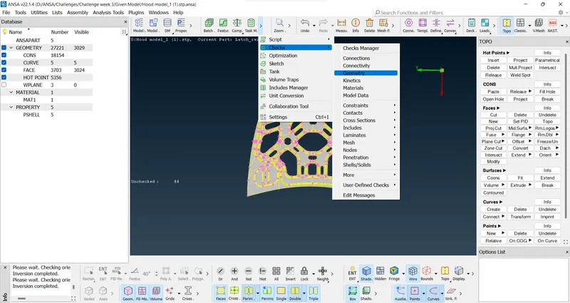
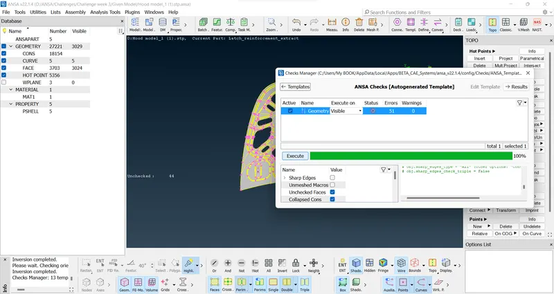
Figure: Geometry check on Inner extract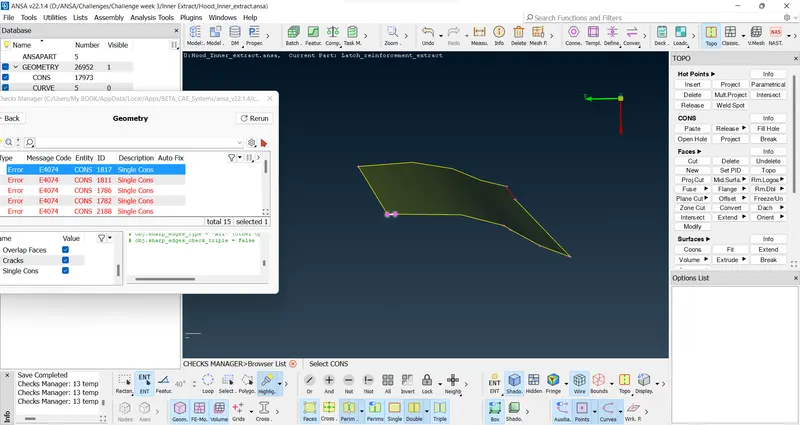
Figure: Errors in Geometry check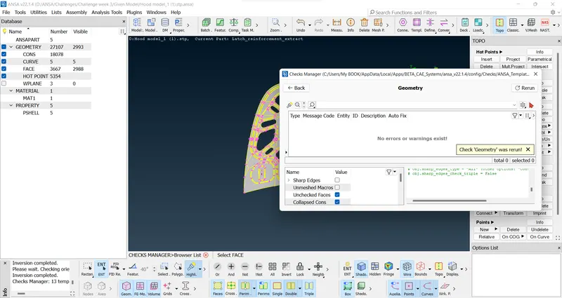
Figure: After Fixing the errors on Inner extract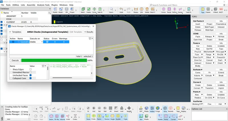
Figure: Geometry check for Hinge reinforcement extract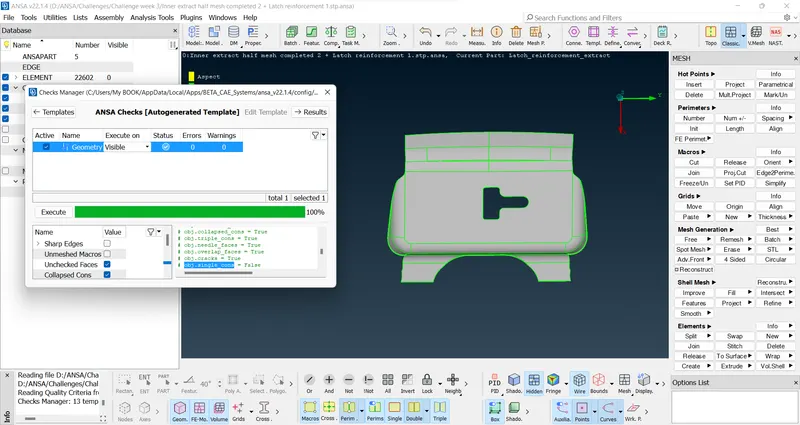
Figure: Geometry check for Latch reinforcement extract
Step 3: Mid-surface generation
- Hood or Bonnet is considered to be a sheet metal component(thickness<6mm).Hence we carry out meshing on midsurface of the component.
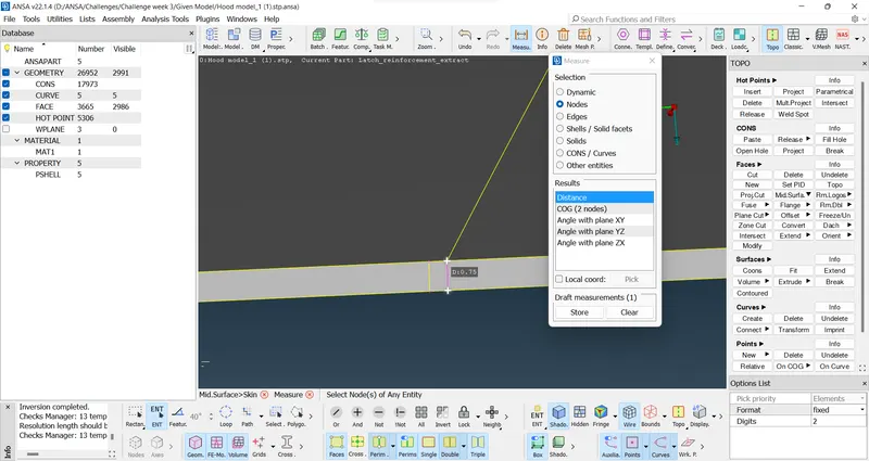
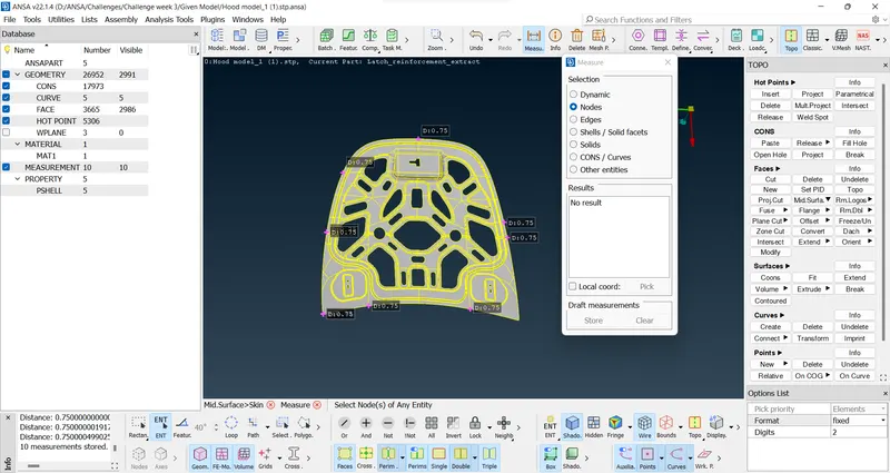
Figure: Measuring thickness of Inner extract
In the given model, Inner and Outer extracts have a thickness of 0.75mm while Latch and Hinge reinforcement extracts are 1.2mm thick. - Since the given model(Hood) is a sheet metal component, there are two ways by which we can extract the midsurface. First is the automatic method known as 'skin' and other is manual method known as 'offset'.
TOPO module → Faces → Mid Surface → Skin → Select the enitre component → Middle mouse click → Edit Areas window pops up → Ensure that one entire surface of the component is Red colour, the other Green and thickness in Blue → Middle mouse click → Skin offset value window pops up → Middle mouse click → Midsurface is generated.
Note: While using Skin option for midsurfacing be sure to uncheck 'Delete original faces' option in the options list. Else the parent component will be deleted upon generating the midsurface.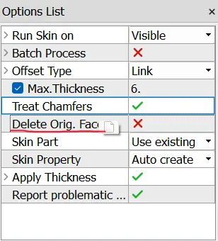

Figure: Generating Midsurface using skin option for Latch reinforcement extract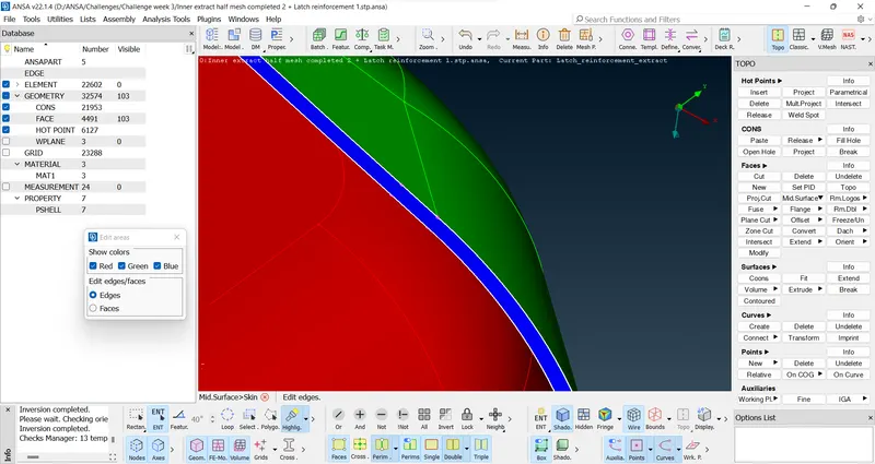
Figure: Checking for Red, Blue, Green colour code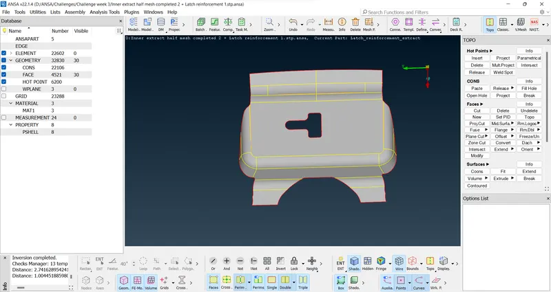
Figure: Midsurface of Latch reinforcement extract
TOPO module → Faces → Offset → Select entire surfaces on one side of the component using Feature selection tool → Give Offset value as '±Half of thickness' depending on the normal direction, change property to 'Auto create' in options list → Click OK → Select 'No' for Delete original faces window.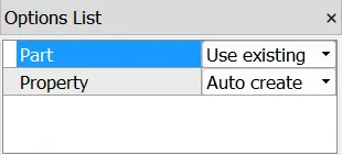
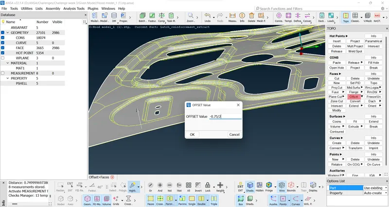
Figure: Extracting the Midsurface of Inner extraxt using Offset option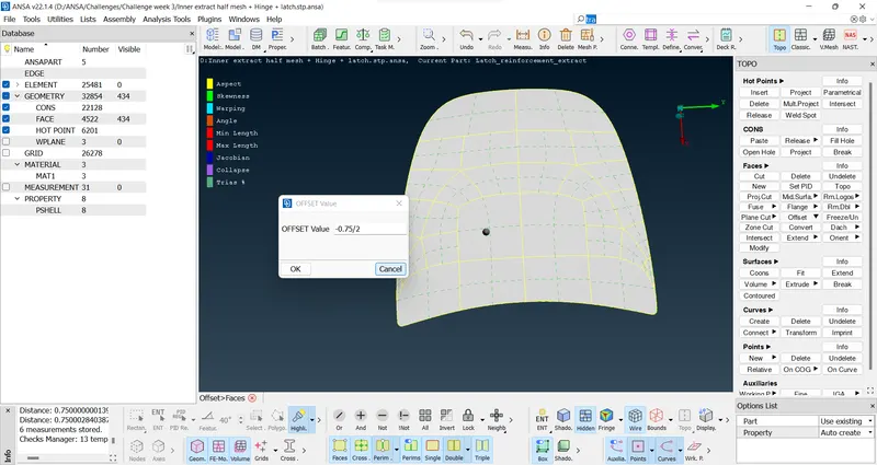
Figure: Offsetting Midsurface of Outer extract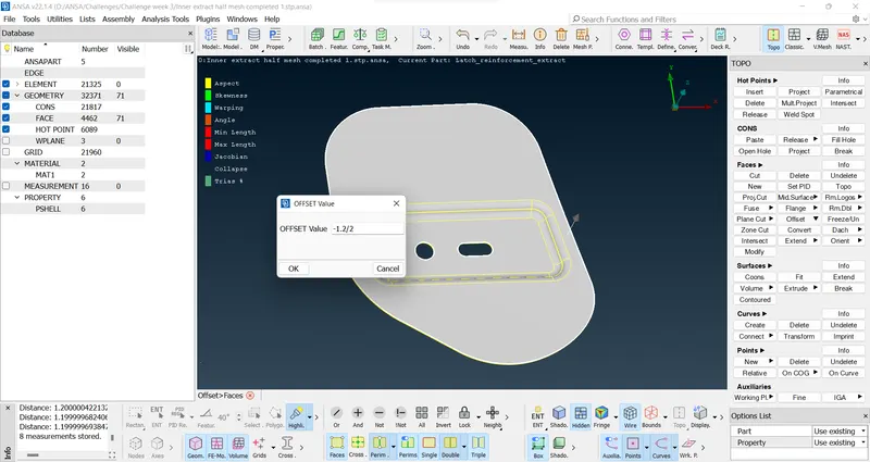
Figure: Offsetting Midsurface of Hinge reinforcement extract - For this challenge, I have used offset option for most of the components except Latch reinforcement extract, for which I used skin option. For large and complex geometries like inner extract it is better to go with Offset option. Otherwise, we need to check and correct for red,blue and green surfaces as mentioned earlier which will be a tedious process. For smaller components, we can go with Skin option.
- Soon after obtaining the midsurface, we need to perform cons resolution on it with perimeter and macros values equal to 'Target element length'.
Mesh module → Perimeters → Length → Perimeter/macros(do for both) → select the whole surface → middle mouse click → gave the value as target element size(It is 5) → apply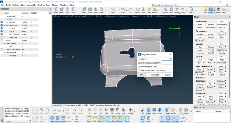
Figure: Cons resolution for Latch reinforcement Midsurface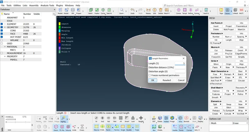
Figure: Cons resolution for Hinge reinforcement Midsurface - For components which are symmetric, for example, inner and outer extracts in this particular case, it is better to trim the midsurface at the plane of symmerty and carry out meshing only on half portion of the component.Later the mesh on the other half can be generated by tranforming this mesh along with the midsurface with respect to plane of symmetry. This effectively reduces the mesh time and human effort. The same Transform tool is applicable for Hinge reinforcement extract as well.
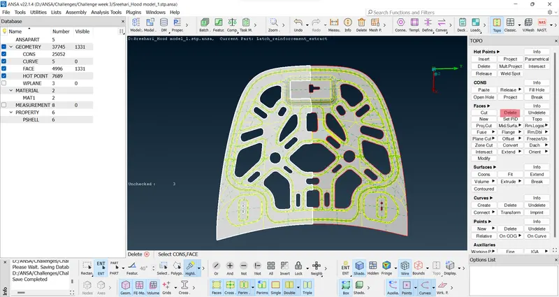
Figure: Deleting symmetric half of Inner extract midsurface
TOPO module → Faces → Delete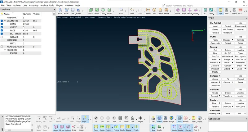
Figure: After Deleting symmetric half of Inner extract midsurface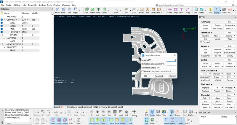
Figure: Cons resolution for Inner extract Midsurface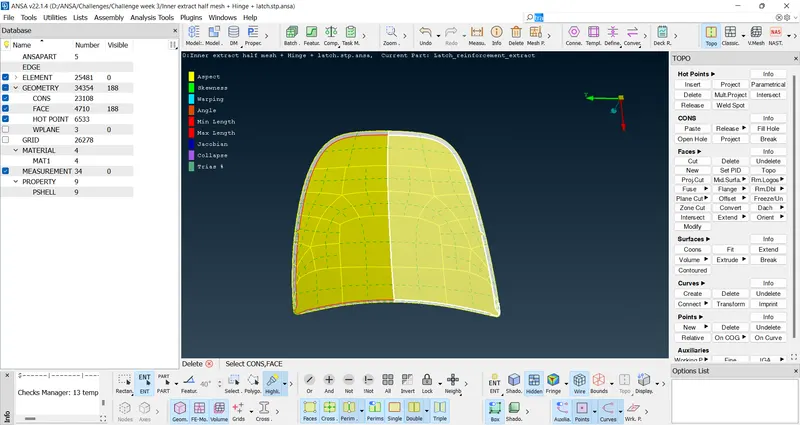
Figure: Deleting symmetric half of Outer extract midsurface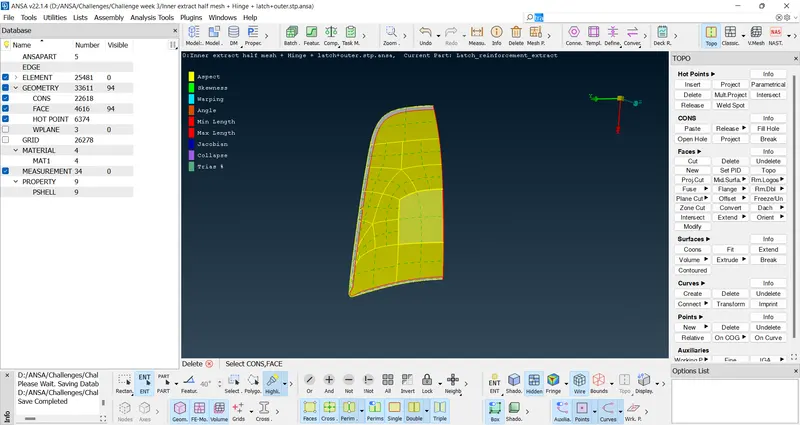
Figure: After Deleting symmetric half of Outer extract midsurface
Step 4: Geometry cleanup on Midsurface
- In this step we check the midsurface and suppress those double cons which are very close to one another such that the distance between them falls below the minimum element length allowed. For this, we use 'Cut' option in Macros group under the TOPO module.We also try to avoid sharp corners in construction lines by slightly changing them using the same cut option. Apart from these, we try to split the surface into small square-like structures so that the mesh flow will be better.
TOPO module → Faces → Cut → Right click suppresses the double con → Left click cuts the surface.
The same option is available under Mesh module as well.
Mesh module → Macros → Cut → Right click suppresses the double con → Left click cuts the surface.
The supressed cons appear in orange colour under TOPO module while they won't be visible in Mesh module.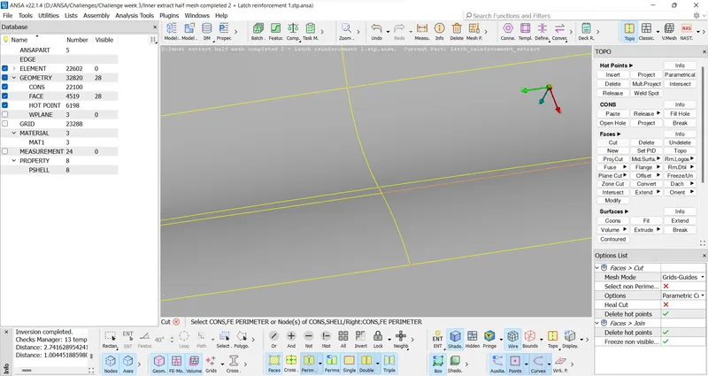
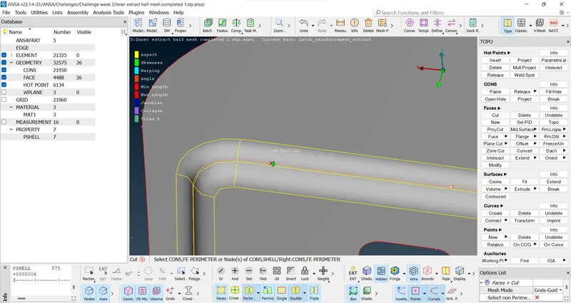
Figure: Suppressing double cones - We may also add washer splits to holes so that the features can be captured properly and there won't be trias near the holes in the 2D mesh. This is done using the option
TOPO module → Faces → Zone Cut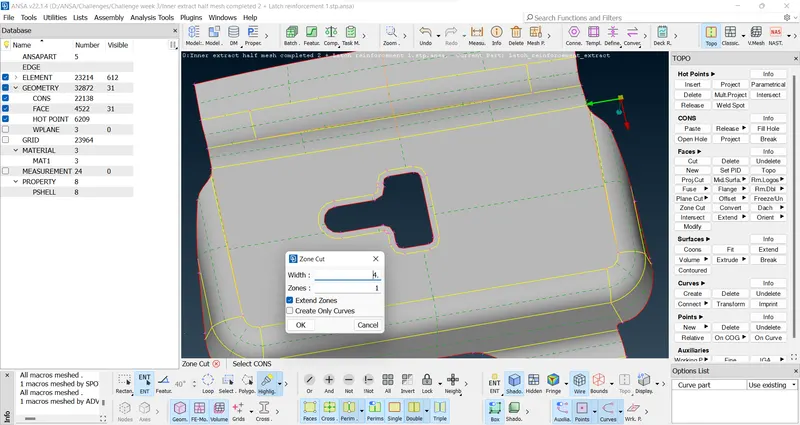
Figure: Zone cut on Latch reinforcement extract - Also delete unnecessary hotpoints. Otherwise they may distort the meshflow.
TOPO module → Hot points → Delete → Left mouse click or
TOPO module → Hot points → Insert → Right mouse click - In the hemming region(in the Outer panel’s bend region), Elements will fail for the Min length error due to the very small surface to capture the curved surface.
In order to solve this Min length error, One can toggle (suppress) the top and bottom double cons at the fillet region of a mid surface. This is called ‘defeaturing’ the midsurface.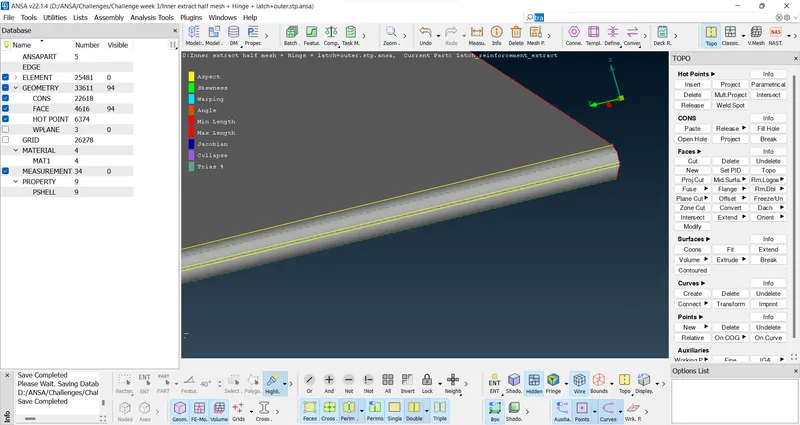
Figure: Outer extract hemming region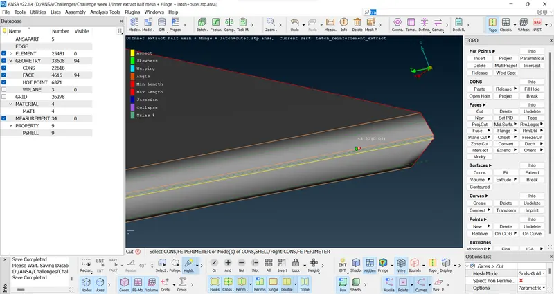
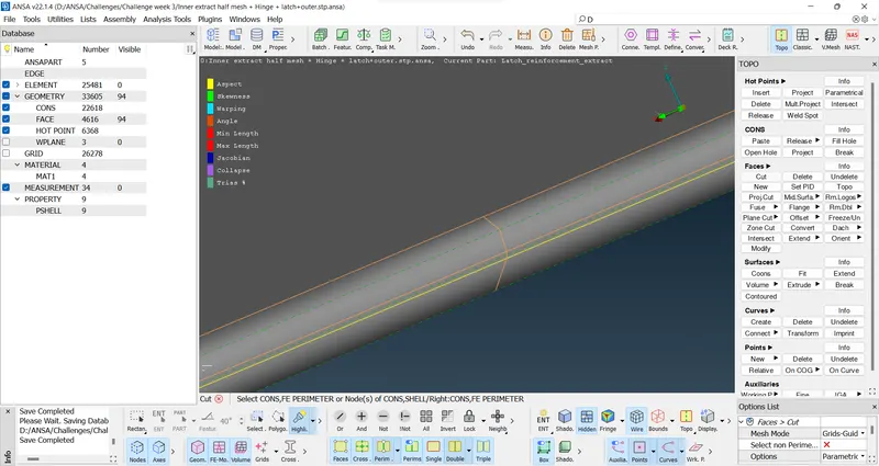
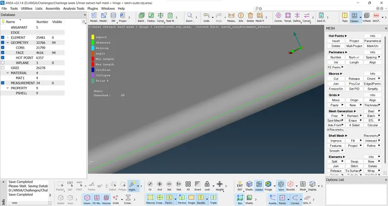
Figure: Outer extract hemming region after correction - The midsurfaces after geometry cleanup are shown below.
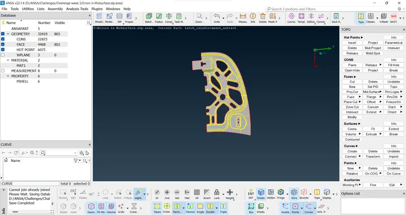
Figure: Midsurface Inner extract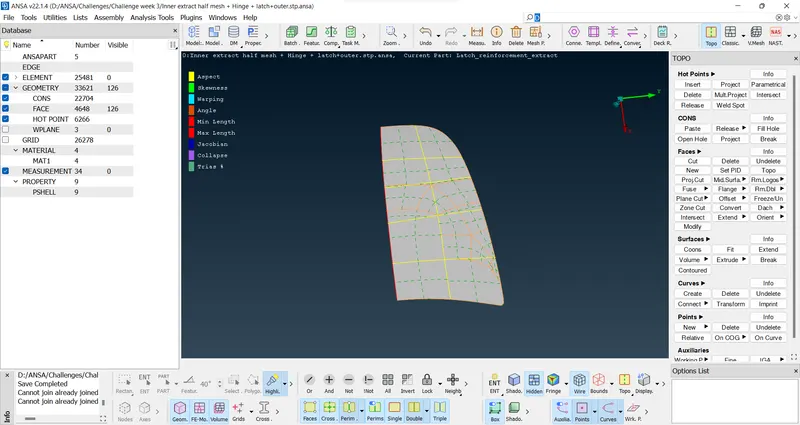
Figure: Midsurface Outer extract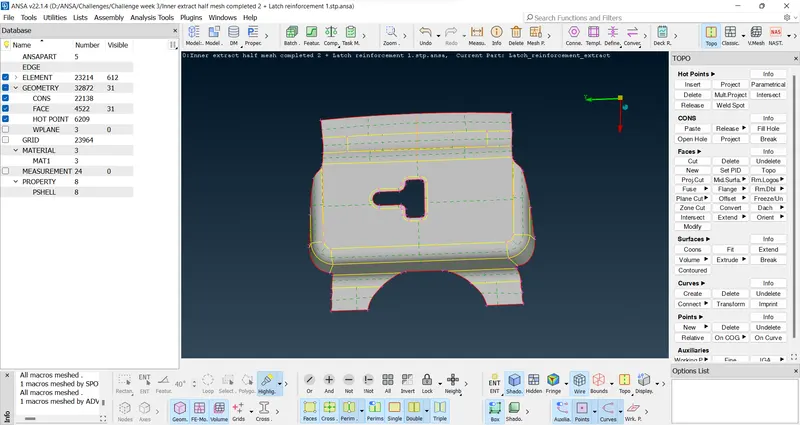
Figure: Midsurface Latch reinforcement extract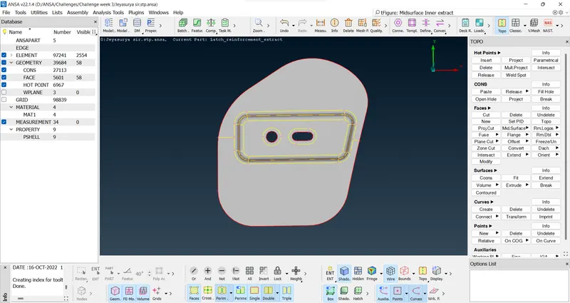
Figure: Midsurface Hinge reinforcement extract
Step 5: Setting the Criteria and Parameter files
- We have to set the quality criteria as well as mesh parameter as specified.
Utilities tab → Mesh Parameter → Set Element type: Mixed , target element size, minimum element size → Ok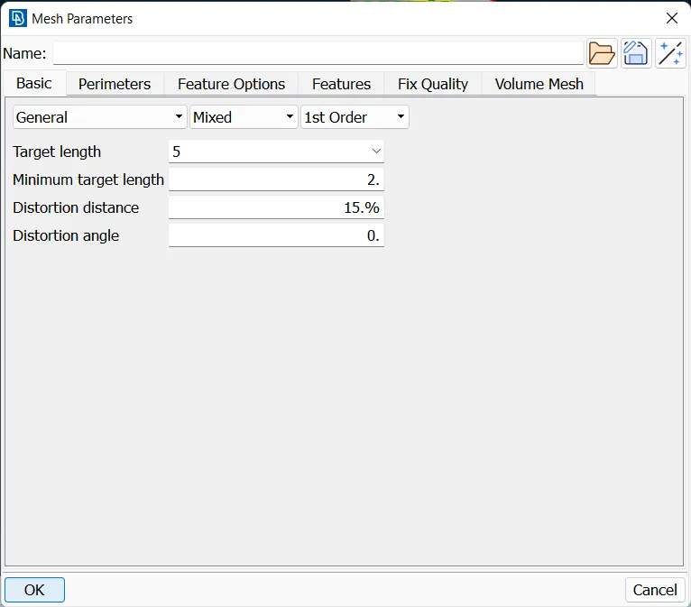
Figure: Mesh Parameter file
Utilities tab → Quality Criteria → From Shell tab set 2D element qualities → Ok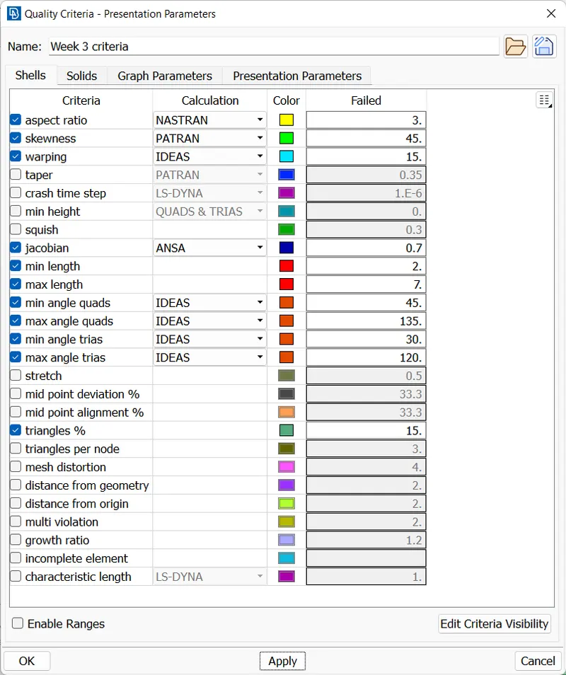
Figure: Quality criteria file - We also save them to be used later.
Step 6: Meshing
- We generate 2D mesh on the midsurfaces which have undergone geometry cleanup. For this, select 'Best' option from Mesh generation group in the mesh module. Select the surfaces to mesh, and middle mouse click.
Mesh module → Mesh Generation → Best → Select the surfaces → Apply (Middle mouse click). - Here we are using mixed mesh(quads and trias) because we are preparing the model for crash & safety simulations. The quad-only mesh is preferred for durability and structural simulations.
- The initially obtained mesh may not be of high quality. We edit it by using Reconstruct option and ensure that there are no off elements(elements failing quality criteria) when viewed in Hidden mode.
Mesh module → Shell Mesh → Reconstruct. - Other options like split, smooth, Num+/-, Move etc can be used to correct mesh flow.
Mesh module → Shell Mesh → Smooth
Mesh module → Elements → Split → Left click splits quads into trias → Right click acts as Swap edge and combine trias
Mesh module → Perimeters → Num+/-
Mesh module → Macros → Move etc.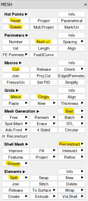
Figure: Some commonly used options in ANSA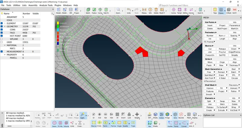
Figure: Errors while meshing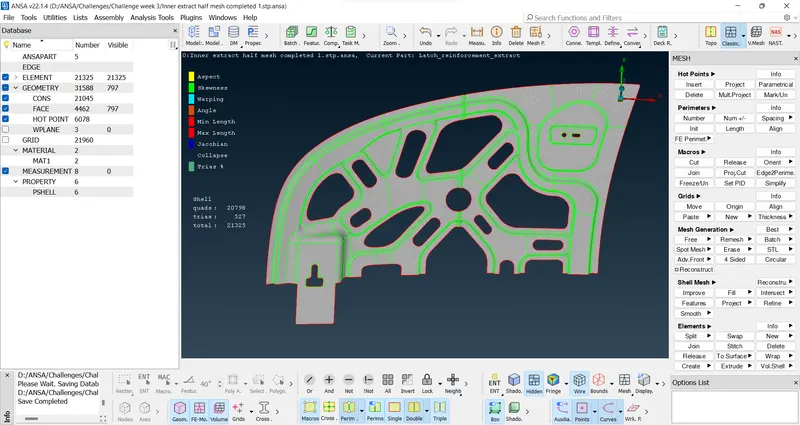
Figure: Half of Inner extract after meshing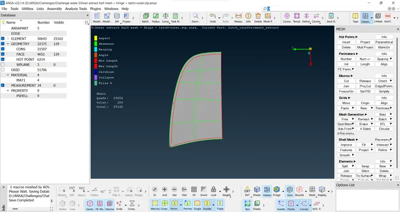
Figure: Half of Outer extract after meshing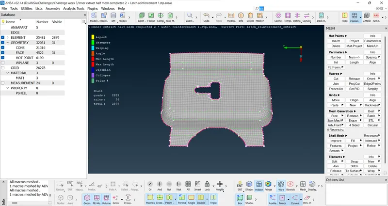
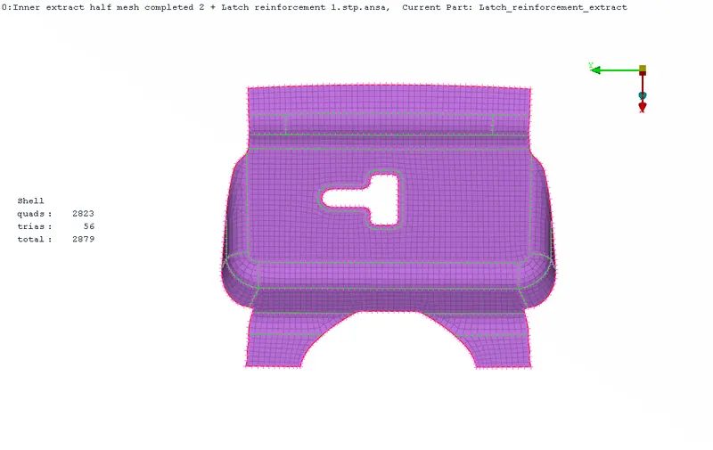
Figure: Latch reinforcement extract after meshing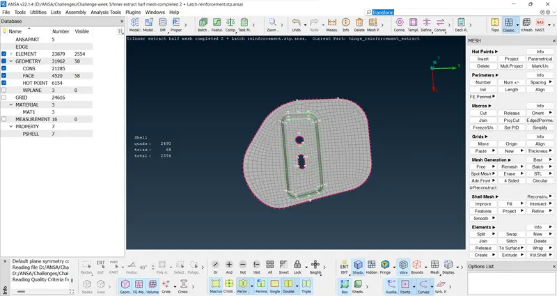
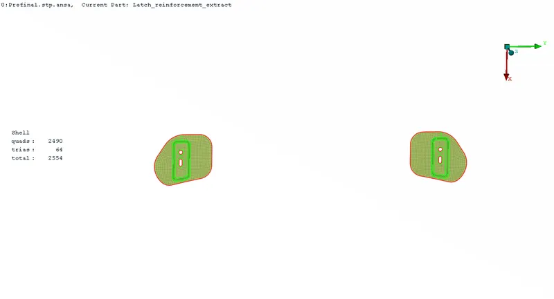
Figure: Hinge reinforcement extract after meshing
Step 7: Completing the mesh using Transform Tool
- Except for the Latch reinforcement, for the rest of the three components we need to reflect the mesh on to its other half. This is done by using the option
Utilities → Transform → Copy → Select entities(Surface+Mesh) → Symmetry → Default Symmetry Plane → Apply → Finish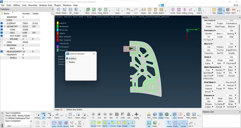
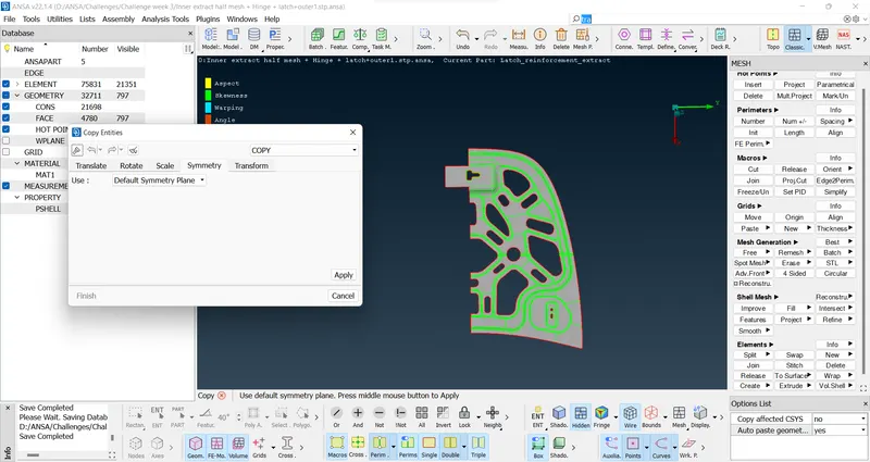
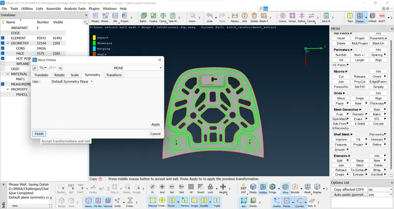
Figure: Transforming Inner extract - Use Topo incase any single cones present
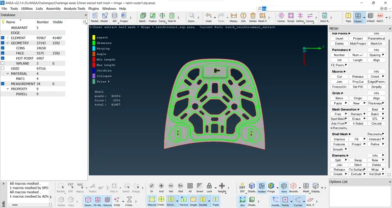
Figure: Transformed Inner extract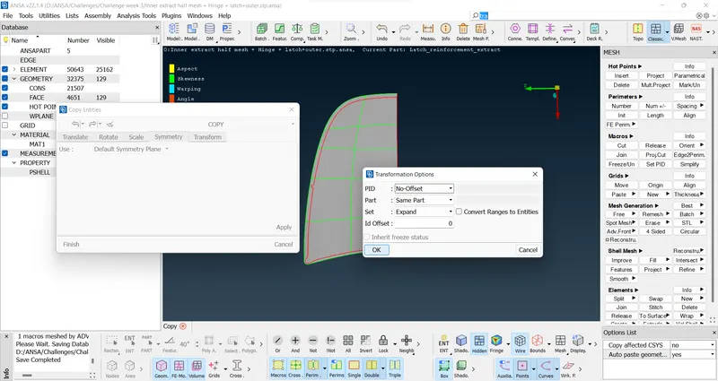
Figure: Transforming Outer extract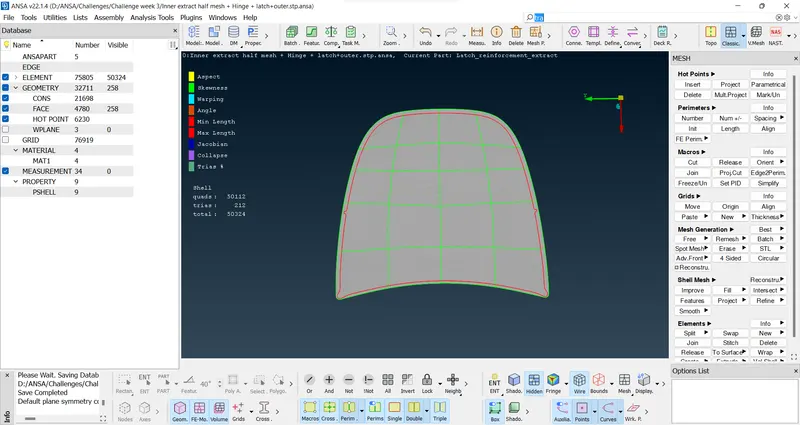
Figure: Transformed Outer extract - Finally ensure that there are no off elements by viewing all the components in Hidden mode.
5.Outputs:
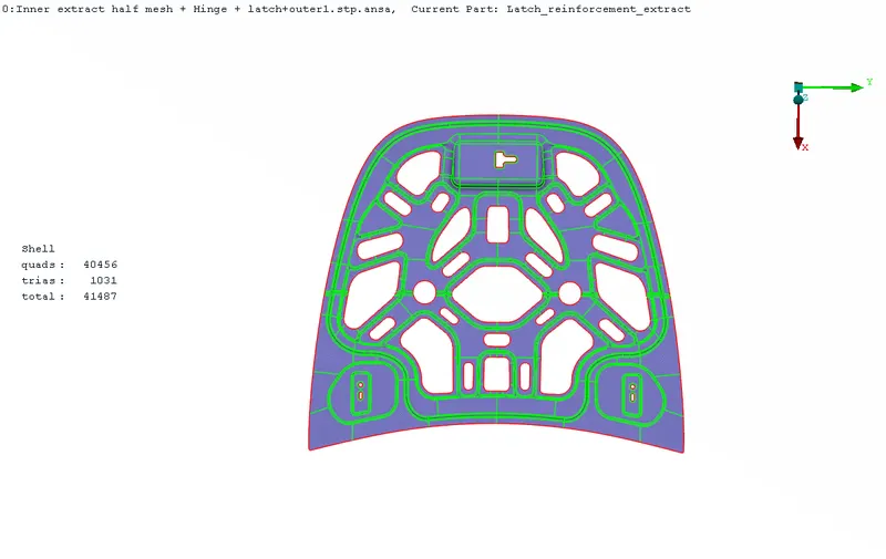
1.Inner Extract Final Meshed Component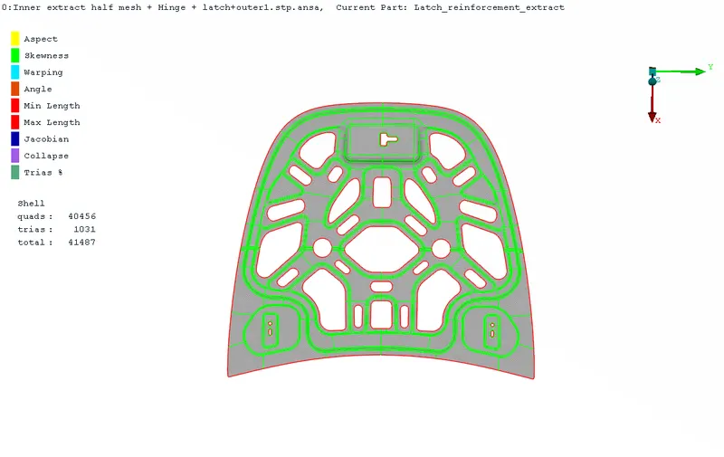
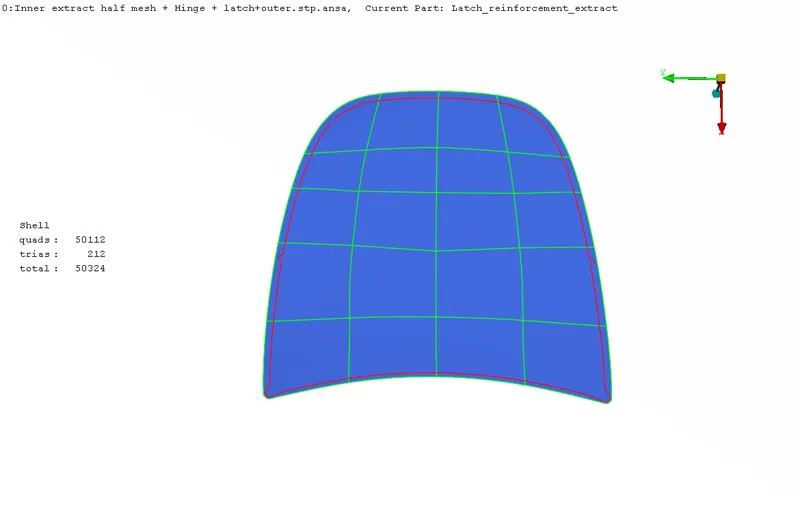
2. Outer Extract Final Meshed Component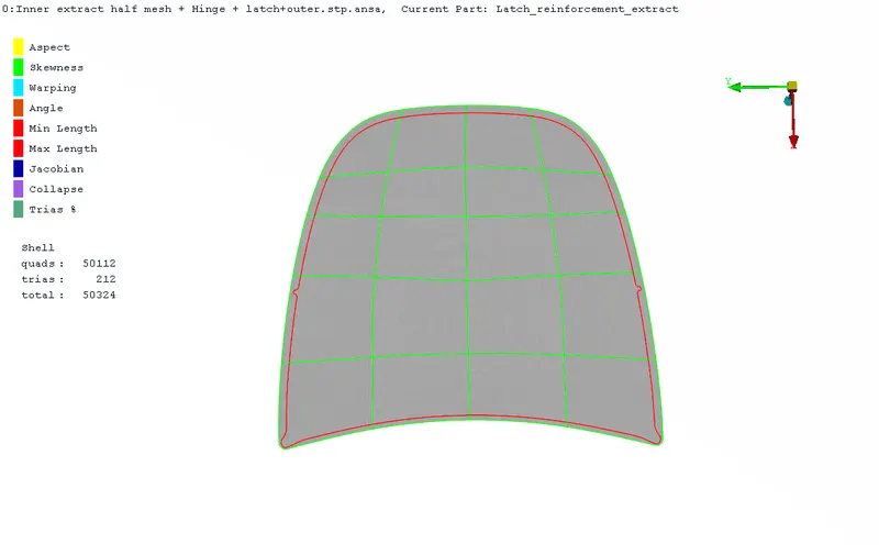
3. Latch Reinforcement Extract Final Meshed Component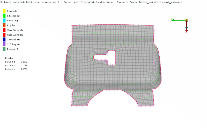
4. Hinge Reinforcement Extract Final Meshed Component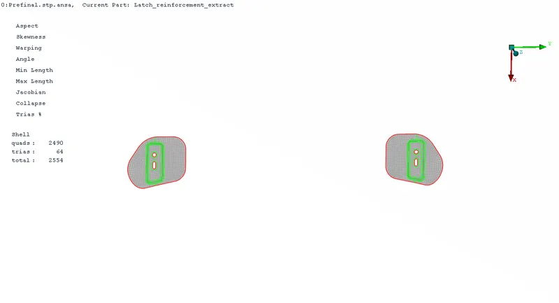
6. Results:
- Extracted the midsurface of each of the four subcomponents[Inner extract,Outer extract,Latch reinforcement extract and Hinge reinforcement extract] of the hood separately after checking the geometrical errors.
- Generated 2D mesh on the extracted midsurfaces as per the given quality criteria.
- Features in the model have been captured properly with good mesh flow.
- Since my file size exceeds the permissible limit in the answer box, Iam uploading Google drive link for the same as adviced by one of the TSEs.
https://drive.google.com/drive/folders/1wm0E-RonXpDrmtRykaiBViZVhJL9haxJ?usp=sharing
7.Outcomes:
- This challenge helped me to understand and have hands on experience on midsurface extraction methods for Sheetmetal components, i.e, skin and offset.
- This challenge also helped me to have hands on experience on meshing complex sheet metal geometries.
- I learnt to do various checks on the given component like single cons check, orientation check etc.
- It gave me knowledge on various tools in ANSA to correct quality of elements and meshflow.
- I learnt to do mesh modelling on a component in an orderly manner.
8.Conclusions:
2D meshing of Hood is a really good challenge which would help starters to understand and to have hands on experience on various tools in ANSA. The inner extract is the major component to put our focus on followed by rest of the components which are comparitively easy. Also, since this file turned out to be large, I have uploaded google drive link for the same in the Results(Section 6).