Week 4-1D Element Creation Challenge
Meshing and Creation of 1D Elements using HyperWorks
1.Aim: To mesh the given component with the Target Element Size of 5 Units and create the mentioned 1D elements on the following component with given cross-section and DOF.
2.Objectives:
- To mesh the given Parallel Bracket Component using HyperWorks.
- To create 1D elements on the component with cross-section and DOF as mentioned below:
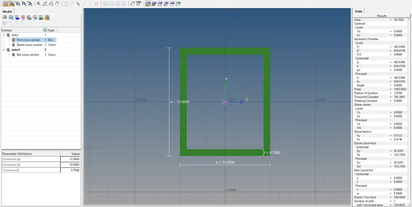
a. Rod element:- Translational DOF should be Constrained with RBE2 link
Cross-Section: BOX- Dimension a= 12 mm
dimension b=10 mm
Thickness t= 0.75 mm
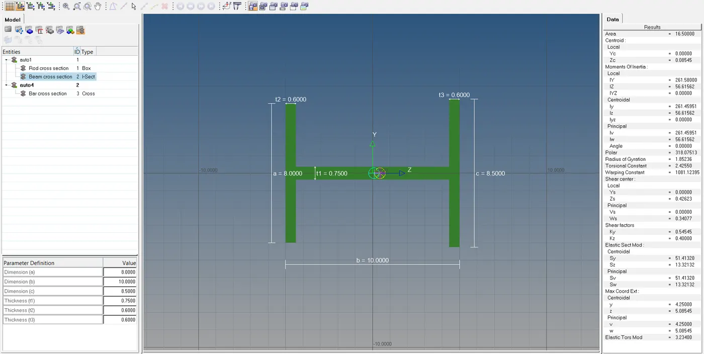
b. Beam element:- All DOF should be constrained with RBE3 link
Cross-Section: I Section- Dimension a= 8 mm
Dimension b= 10 mm
Dimension c= 8.5 mm
Thickness t1= 0.75 mm
Thickness t2= .6 mm
Thickness t3= .6 mm
c. Bar element:- Constrain only x and y DOFs With RBE3 link
Cross-section: X section- Dimension DIM1= 5 mm
Thickness DIM2= 1.2 mm
Dimension DIM3= 10 mm
Thickness DIM4= 1.2mm
d. & e. Apply the mass of magnitude 10 with the RBE2 link
f. Join the two components with Spring elements
Figure 2.1[CAD Model]
3.Theory:
- In HyperWorks,1D elements are basically line shaped elements which are created by two nodes.
- 1D elements can be applied to 2D and 3D model by analyzing the indiviual line element that form the model's infinite element mesh.
- 1D elements are useful for stimulating how different section of the mesh will react to certain condition.
- Example of 1D elements are RBE2,RBE3,ROD,BAR,BEAM,SPRING element.
- RBE2 are basically elements which have infinite stiffness.RBE2 will distribute the load equally to each element irrespective of their position/distance from Independent node.
- RBE3 elements can be moved up,down,forward or backward as per the applied load.Load distribution will be more for the elements which are near to Independent nodes than the elements which are comparitively far from Independent nodes.
- Spring elements are elastic elements.
- Rods are rigid elements used for Tensile and Compressive loading applications.
- Bars allow Bending in addition to Tension and Compression.All 6 dof are allowed. But it is used only for symmetrical sections.
- Beams are similar to bars but they are used for asymmetrical sections.
4.Procedure:
- Firstly, we open HyperWorks and choose the user profile as "OptiStruct".
- Then we import the given IGES file using the 'Import Model' option.
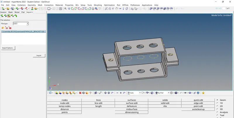
- Select the first bracket,go to `Geomrightarrow midsurfacerightarrow "automidsurface"to"extract` in order to extract the midsurface.We ecxtract the midsurfaces of two brackets separately and name them as "Midsurface Bracket 1" and "Midsurface Bracket 2" and give them orange and green colour respectively.We then Delete the solid componenets and hide the part so that the midsurfaces are clearly visible.
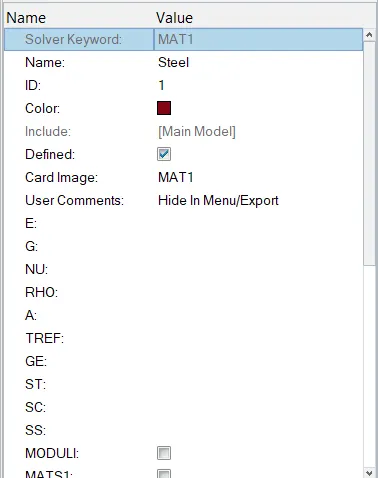
- Assign material by `right clicktocreatetomaterial`.Rename the material as Steel.
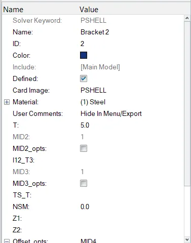
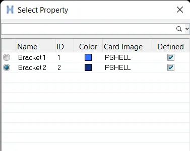
- Create properties for brackets 1 and 2 by `create to "properties"` and rename them as "Bracket 1", "Bracket 2"
- Click on these properties and assign thickness value 5 for each of them, keep the element type as "PSHELL" and add material(i.e. Steel).
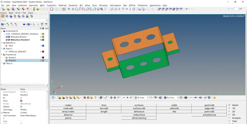
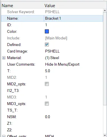
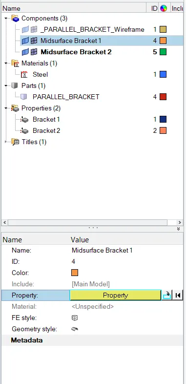
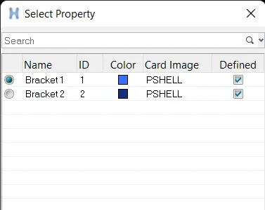
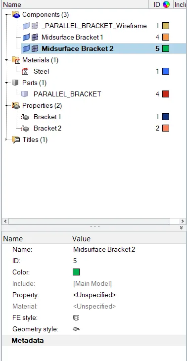
- Go to components, click on "Midsurface Bracket 1" and assign proprties to it and same as for "Midsurface Bracket 2"
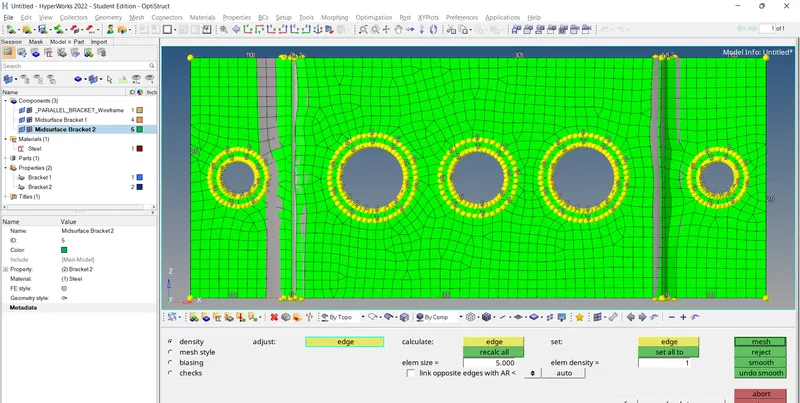
- Now, we are going to mesh the geometry. For that firstly choose the 'autocleanup' option from 'Geom'.Then we add 'washer split'(5mm offset).Go to `2D to "automesh"tomesh`.Make sure that the number of nodes in washer split and hole remains the same.
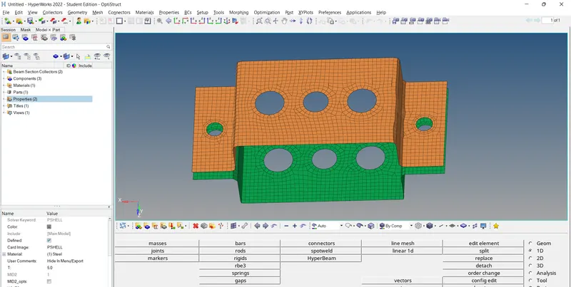
- Afterwards, I have tried to improve the quality of the mesh(reducing the tria elements) by choosing the options `2D to "rebuild mesh", 2D to "elem cleanup", 2D to "qualityindex", 2D to "edit element"`
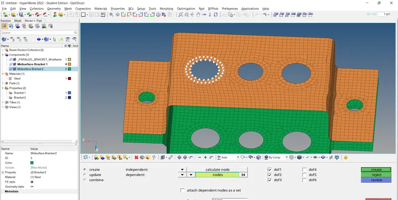
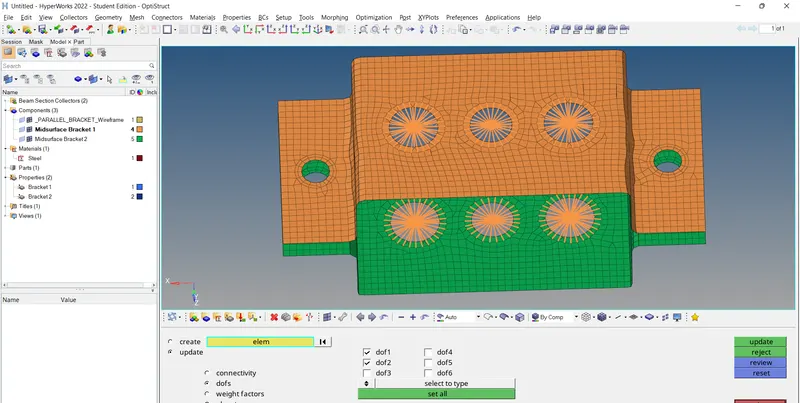
- Then we create the rbe2 and rbe3 elements at the respective positions as per the specifications given in the question.For rbe2 elements,go to `1Dtorigids rightarrow "select the independent and dependent nodes" to create` and for rbe3 elements the option is `1Dtorbe3 rightarrow "select the independent and dependent nodes" to create`. The Degrees of Freedom are constrained by putting a tick mark to the 6 dof check boxes as per requirement. The first 3 dof represent translational dof while the latter 3 represent rotational dof. Later on, these rbe2 and rbe3 elements can be updated using the update option as well.
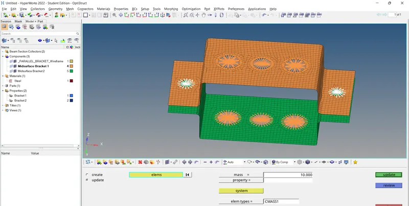
At 'd' and 'e' positions, a mass of magnitude 10 units are added in addition to rbe2 links.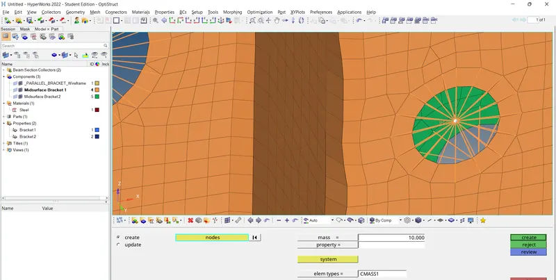
- In this step, we create the rod, beam and bar to be connected to these rbe2 and rbe3 elements. For this the options used are `1D to "rods"to "create"to "choose the nodes"to"element type as CROD" to create`,`1D to "bars"to "bar2"to "choose the nodes"to"element type as CBEAM" to create`,`1D to "bars"to "bar2"to "choose the nodes"to"element type as CBAR" to create`
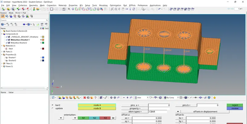
- We have to create the cross sections for these rod,beam,bar. Go to `1D to Hyperbeam to "standard section" to "standard section library"to "standard section type"tocreate`.This will take us to 'Hyperbeam window'. Create the three cross sections as per the given dimensions.
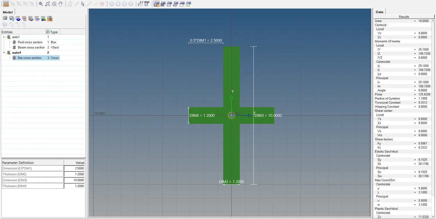
In case of bar section care must be taken because in the question DIM1 is given as 5. Therefore Dimension will be 0.5*DIM1=2.5` - Go bacto to 'Model view', create properties for rod,bar,beam and assign cross sections to them.
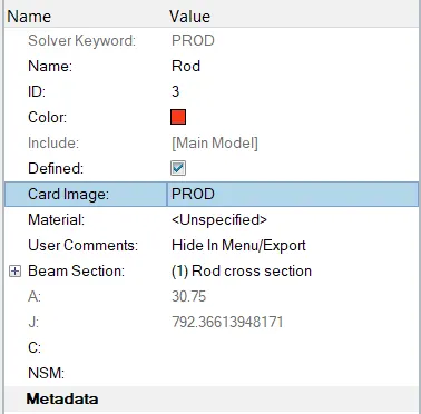
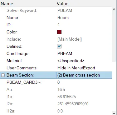
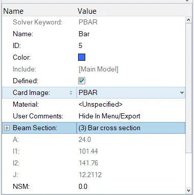
- Now we update the 1D elements i.e, rod,beam and bar with their corresponding properties using `1Dtorodstoupdate`, `1Dto"bars"toupdate`.
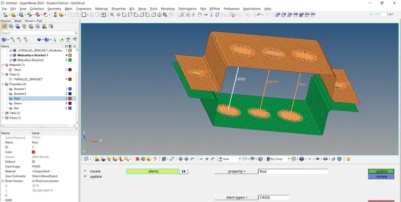
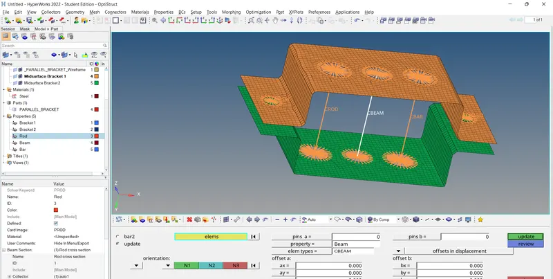
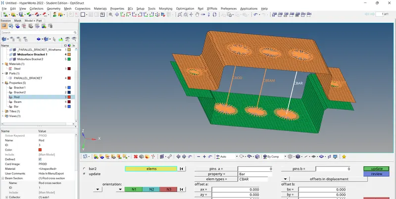
- Finally we create springs at position f(Figure 2.1) by using `1Dto"springs"to createto"choose nodes"to "create"`
5.Outputs:
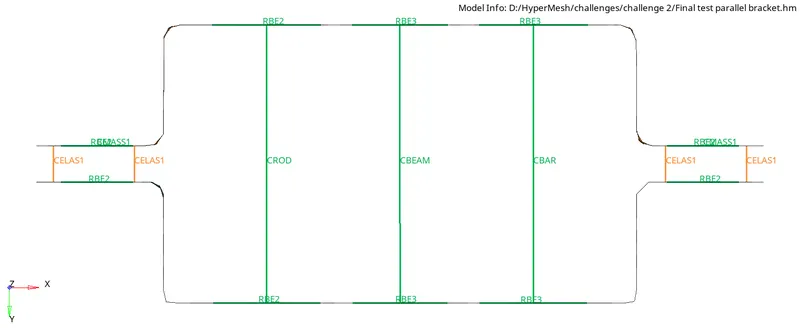
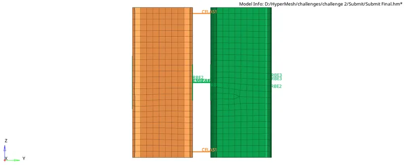
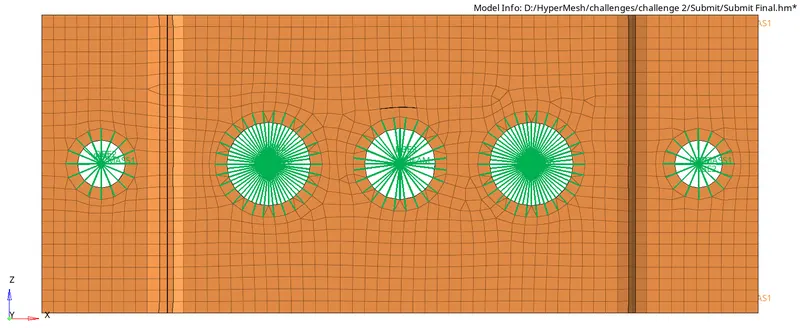
5.1Traditional Element Representation:
Front View
Side View
Top View
Isometric View
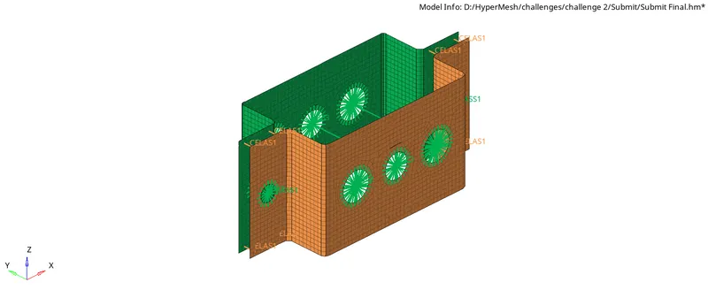
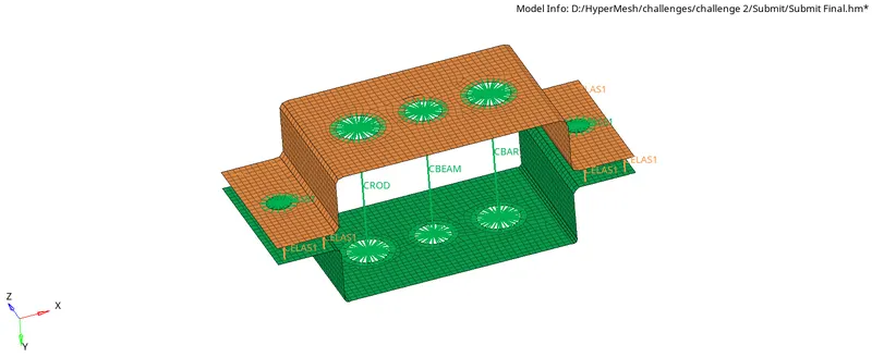
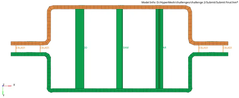
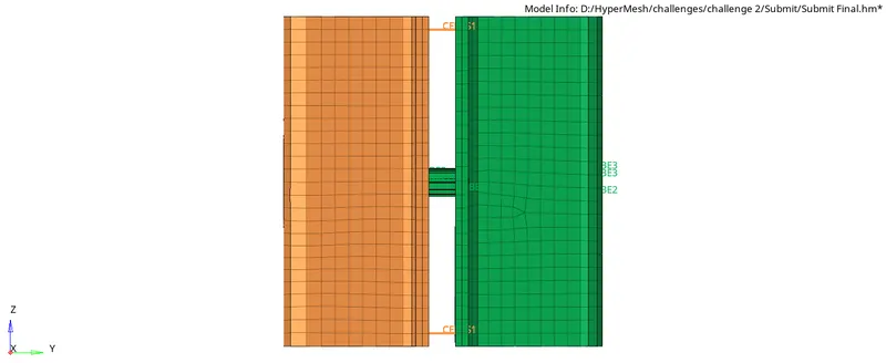
5.2Traditional and Detailed Element Representation:
Front View
Side View
Top View
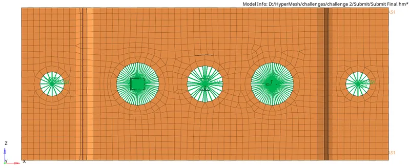
Isometric View
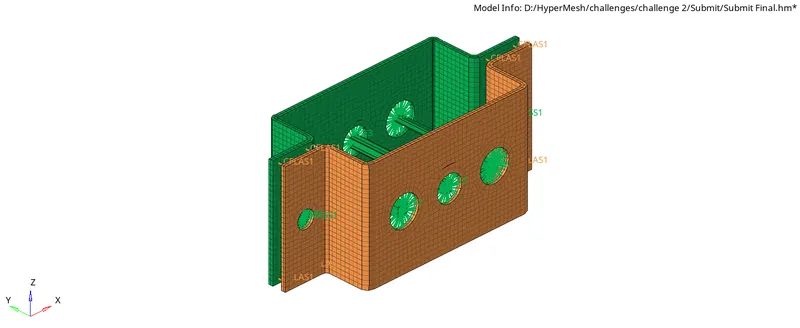
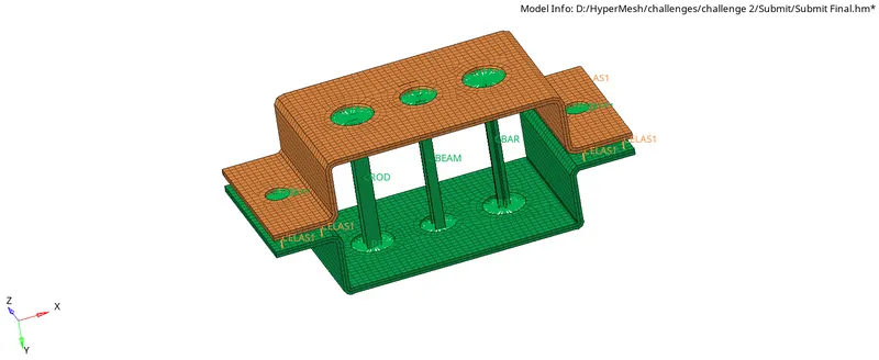
6.Results:
- The given component is meshed using HyperWorks.
- Created 1D elements on the component with cross-section and DOF as mentioned.
7.Conclusions:
- This challenge helped me to learn about various 1D Elements and how they can be used in HyperWorks.
- Through this challenge, I learned to extract midsurfaces,assign properties and cross sections to various components.
- It also helped me to have a little bit more experience on meshing of components.