Week 12:Project 2-Meshing of Rear Wheel Holder challenge
Meshing of Rear Wheel Holder
1.Aim: To mesh the rearwheel holder as per the given quality criteria and assign thickness.
2.Objectives:
- To extract midsurface of the given sheetmetal component(rearwheel holder) using HyperWorks.
- To mesh the midsurface as per the following quality criteria:
Target Element Length = 5 Units
S.N Quality Criteria Value 1 Aspect Ratio 5 2 Skewness 45 3 Warping 15 4 Taper 0.5 5 Min. Length 2 Units 6 Max. Length 8 Units 7 Min angle Quad 45 8 Max angle Quad 135 9 Min angle Tria 20 10 Max angle Tria 120 10 Tria % 10 - To check and validate the quality of mesh using the "qualityindex" and various modal check options available in HyperWorks.
- To measure the thickness and assign material and thickness to the component.
3.Theory:
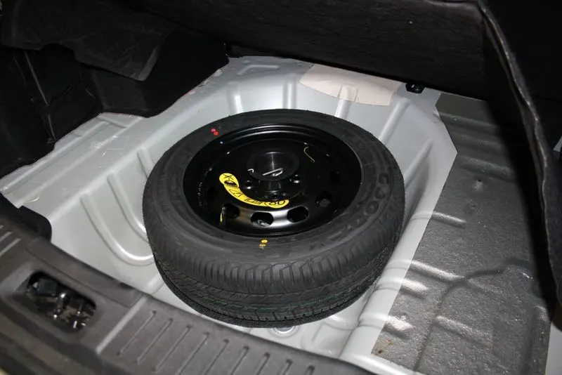
- A spare tyre or stepney is an additional tyre carried in a motor vehicle as a replacement for one that goes flat, has a blowout, or has another emergency.
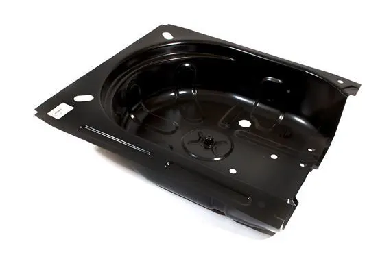
- In most passenger cars, there is a recessed storage space in the trunk for a spare wheel mounted tyre, a jack and a lug wrench. Traditionally produced in stamped steel, and more recently in aluminium, this spare wheel well (SWW, also known as a spare wheel baffle) is a large, heavy, tub-like component that also plays a role in vehicle structure and crash safety.
- The given component i.e, Spare Wheel Well or Rearwheel Holder is a sheet metal component(thickness<6mm).
- Hence, we have to take the midsurface in order to mesh the component.
- Sheet metal is a metal formed by an industrial process into thin, flat pieces.Sheet metal is one of the fundametal forms used in metal working.
- It can also be deformed into varities of shapes.
- Thickness can vary significantly, extremely thin sheets are considered as foil or leaf.
- And pieces thicker than 6mm are considered as plate steel or structural steel.
4.Procedure:
Step - 1: Importing the geometry
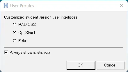
- For this challenge we choose the OptiStruct user-profile.
- Import the given model into HyperWorks using the option File → Import → Import geometry → Choose the file and its type → Import.
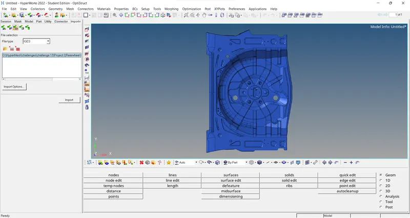
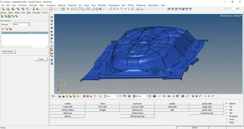
Figure: CAD Model - Then we organise all the surfaces into a single component collector and delete rest of the collectors.
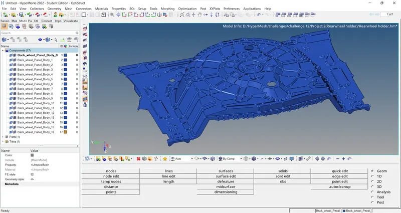
Figure: Given component collectors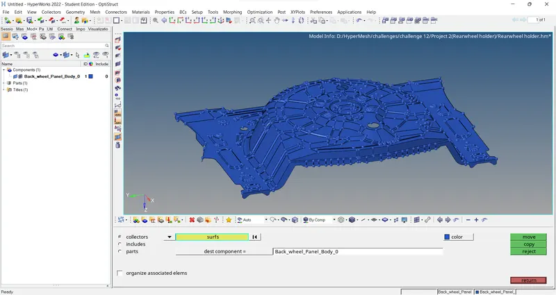
Figure: After organising all the surfaces into single component collector
Step - 2: Setting the Criteria and Parameter files
- We input the given criteria into the HyperWorks software using the options
Preferences → criteria file settings and Preferences → parameter file settings.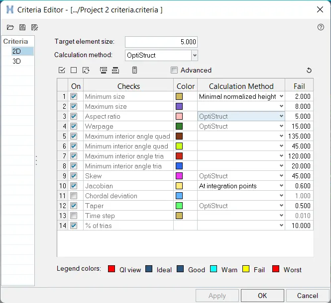
Figure: Criteria File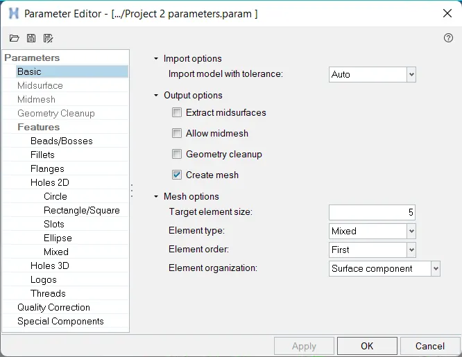
Figure: Parameter File - We also save them to be used later, if required.
Step - 3: Geometry cleanup
- Once the model is imported, we check it in wireframe mode in 'By Topo' view to check for errors like free edges and missing surfaces.
- The rear wheel holder is a sheet metal component and it has a uniform thickness throughout. The cleaning process consists of; closing the small holes, toggling the unwanted lines in the surfaces, defeaturing the small dia fillet areas, splitting the surfaces into parts, filling the empty surface, add/remove the points in the lines, delete the unwanted surfaces.
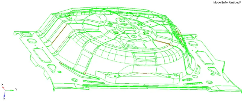
Figure: Checking for errors using wireframe geometry - Such geometry defects can be corrected using the tools like toggle edge,filler surfs, replace points etc. from quick edit panel.
Some of the parent geometry errors before and after correction are listed below: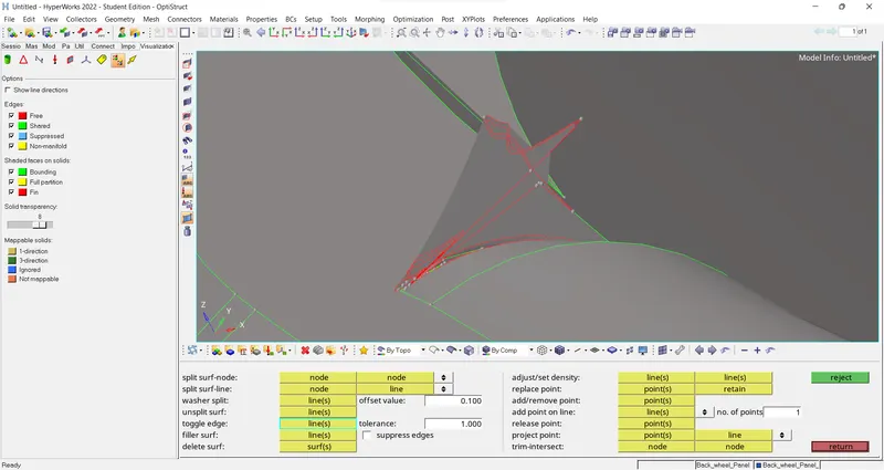
Figure: Error 1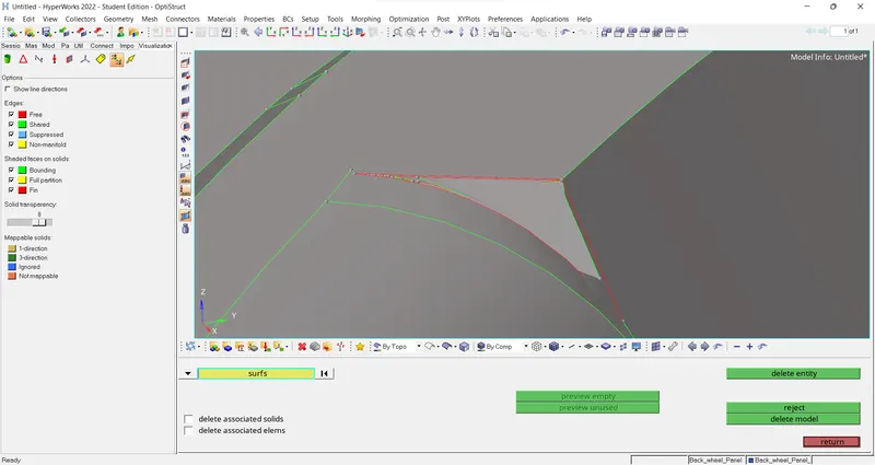
Figure: Correcting Error 1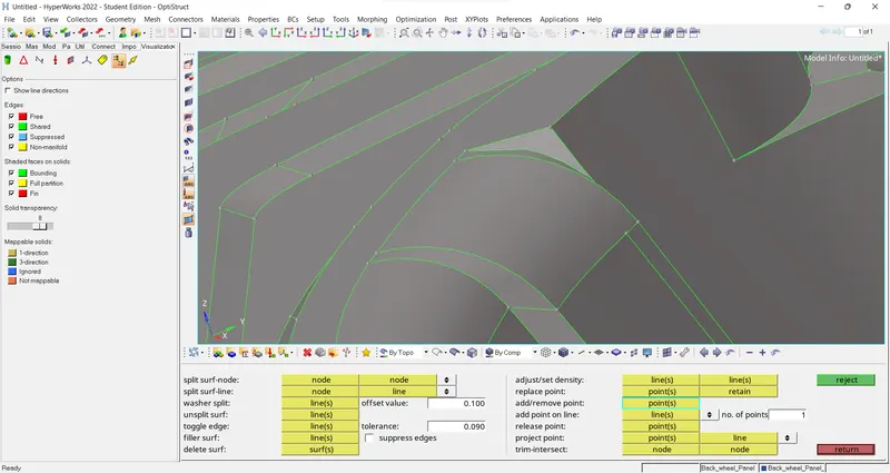
Figure: Error 1 after correction
Error 1 is corrected by using replace point, delete surface and toggle edge tools.
quick edit(F11) → replace point → Select the points to replace and retain.
Delete(F2) → Surface → Select surface → delete entity.
quick edit(F11) → toggle edge → Left click on the edge to toggle it.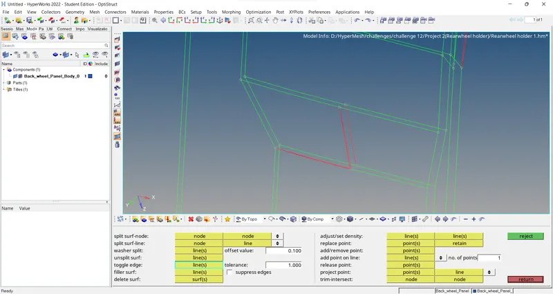
Figure: Error 2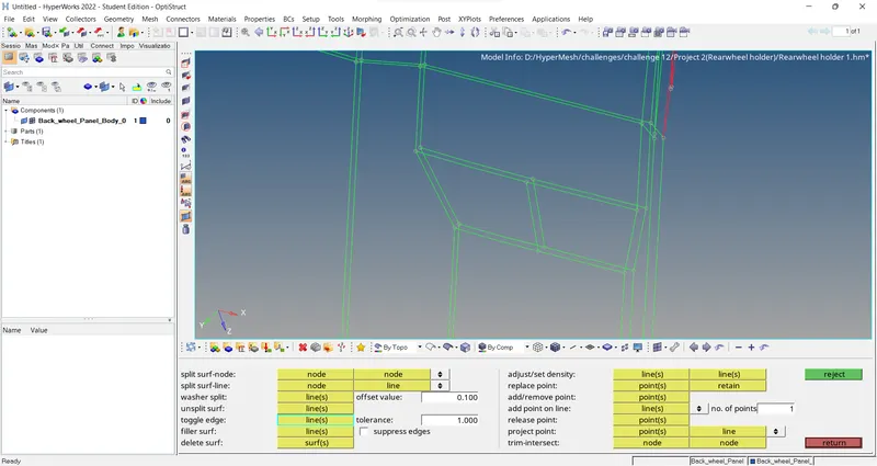
Figure: Error 2 after correction - Remove the buttons which are shown below because it will be difficult to capture that area as well as mesh flow will not be proper. Except this feature, all the other features should be captured with proper element quality.
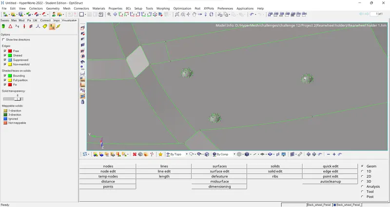
Figure: Buttons to be removed - For this, firstly we delete the surface using the option
Delete(F2) → Surface → Select surface → delete entity.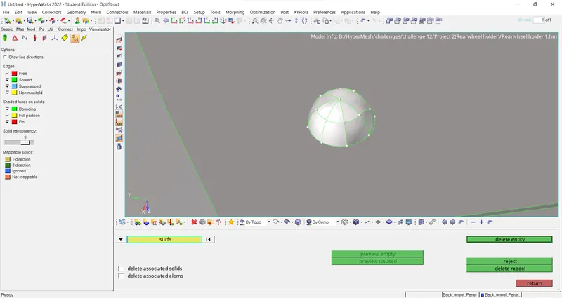
Figure: Deleting button - Then we fill the holes left by removing the button using filler surface tool
quick edit(F11) → filler surf → Select the free edge of the hole.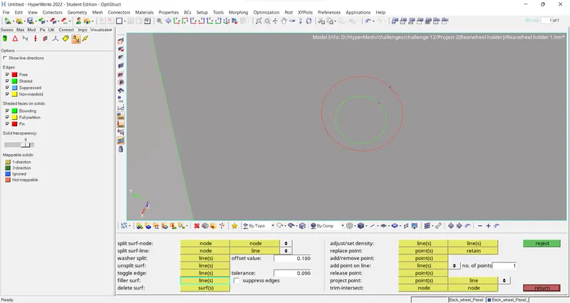
Figure: Correcting button using filler surface tool - Finally we toggle the edge of newly created surface
quick edit(F11) → toggle edge → Left click on the edge to toggle it.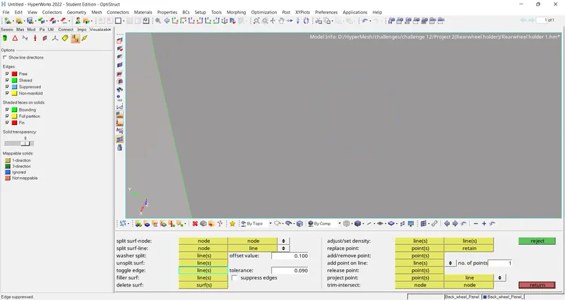
Figure: Button after correction
Step - 4: Midsurface generation
- Before extracting the midsurface, we delete all the solids of the component. This is done using the option
Delete → Solid → Select solid → delete entity. - Since, the given model is sheet metal, we can perform auto-midsurface.
Geom. → midsurface → select automidsurface, extraction option as 'offset' , then select autoextraction → select surface → extract - Rename the midsurface as Middle Surface_thickness. Compare the midsurface with parent body to check whether the midsurface has captured all the features or not. Check for any defects in the midsurface and correct them if any.
- The geomery cleanup on midsurface can be carried out using the same tools as discussed in Step 3.

Figure: Midsurface extraction options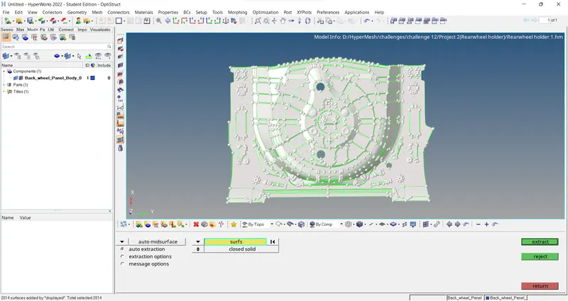
Figure: Midsurfacing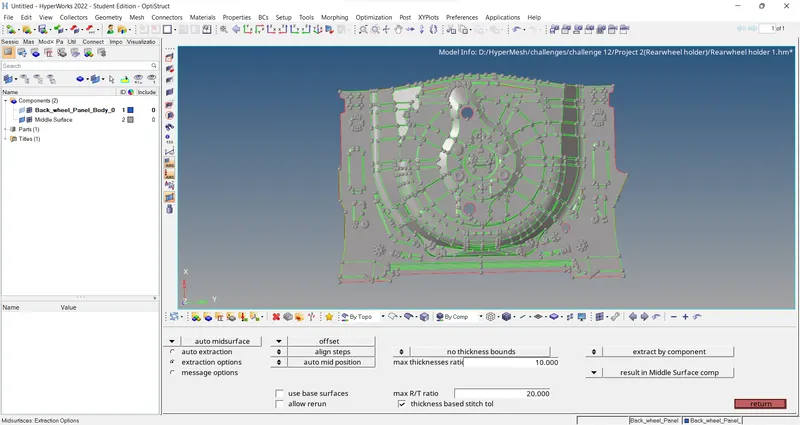
Figure: Extracted Midsurface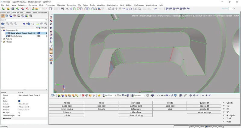
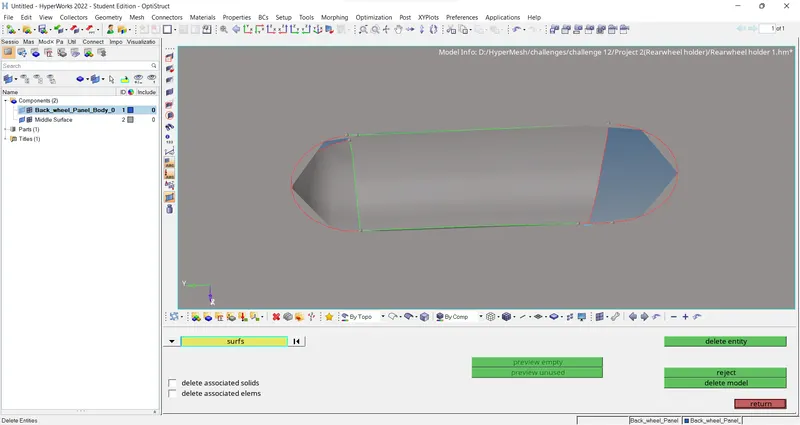
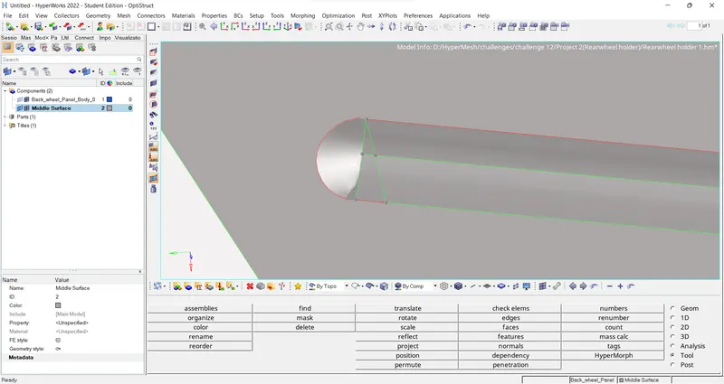
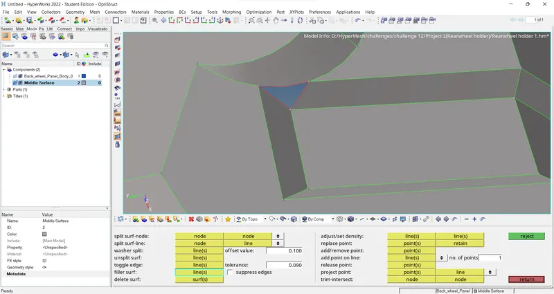
Figure: Errors in Midsurface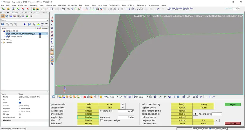
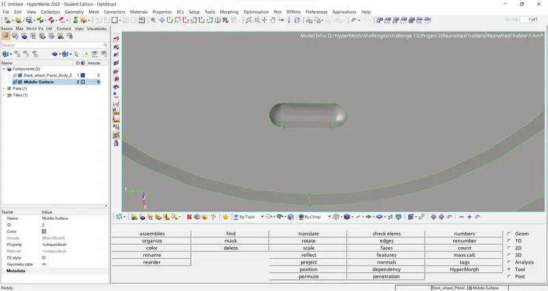
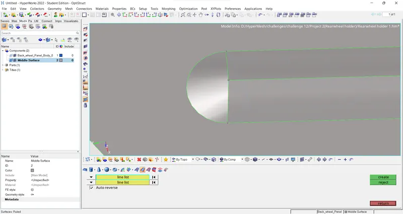
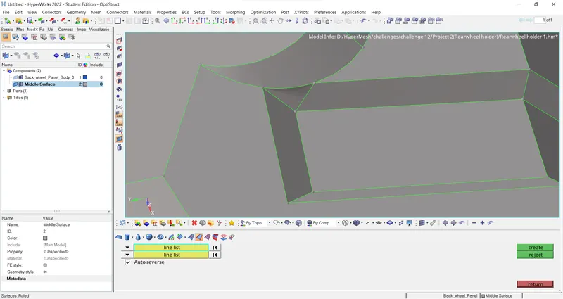
Figure: After correcting the errors - We can also toggle the unwanted lines on midsurface which would disrupt the meshflow or cause the elements to fail.
- The final midsurface obtained after geometry cleanup is shown below:
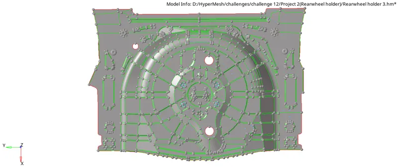
Figure: Midsurface after Geometry cleanup
Step - 5: Meshing
- The next step is to mesh the component.
- To perform meshing on the component, we use the Automesh(F12) command in the 2D panel. Here, we use batch-meshing.
2D → Automesh → Batchmesh/ QI optimize → Select the surface displayed → Select criteria as well as parameter files → mesh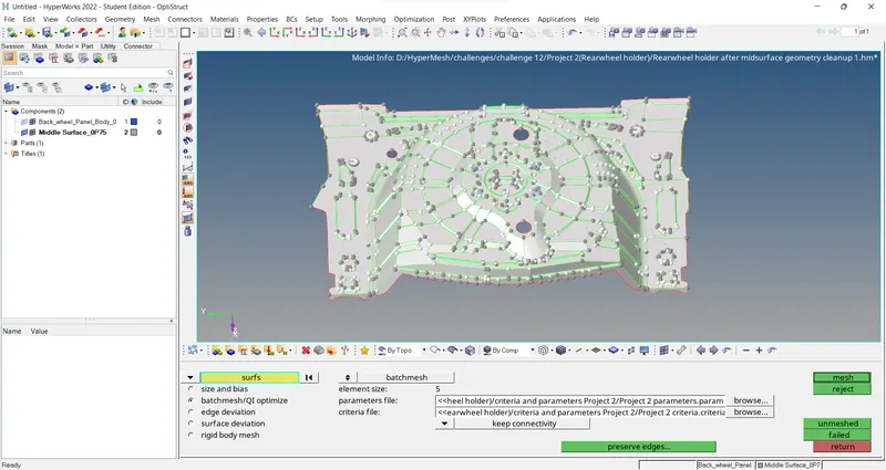
Figure: Batch-meshing the component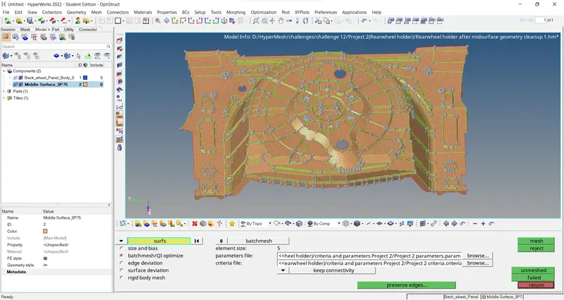
Figure: Batch-meshed component - After meshing, check whether the elements are created in all areas of the surface. Check the mesh created and use 'rebuild' tool at required region. Correct the mesh flow. Try to avoid back-to-back trias, trias touching each other, rotating quads and trias at free edge. Use rebuild, element edit, replace, drag tria tools for that purpose.
- Post meshing, if we are adding any lines or points to the meshed surface, it will distort the created mesh. To avoid this, use disassociate option from topology revision
Preferences → topology revision option → select 2D mesh as disassociate.
But this operation may result in lack of connectivity between elements. So, use replace node option to make connection and perform 'rebuild tool' on those areas to get a better meshing.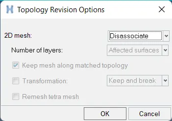
Step - 6: Checking Quality Criteria
- This is the most important step in the entire process.Once after completing the mesh we need to check and ensure that the mesh so generated is as per the given quality criteria.
- For this we use the option 2D → qualityindex as well as Tool → check elems. There might be deviations in some or all of the quality criteria which we need to correct by using the various options available in the cleanup tool option available in the qualityindex.
- We can also use 'distance' and 'element edit' tools for correcting failing elements.

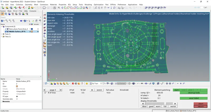
Figure: Deviations in qulatyindex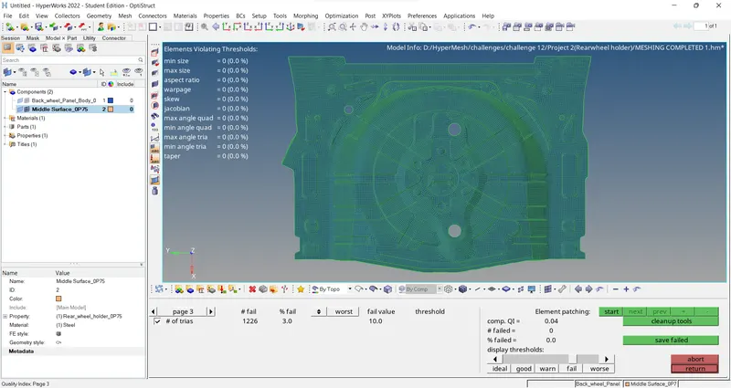
Figure: qulatyindex after correcting the errors
Step - 7: Modal check
- Edges check: Find edges of the modal for perfection.
Tools → edges → select element dispalyed → find edges
If no error noticed, delete edges . Else, Select the elements where there are Free Edges within the geometry → preview equiv → equivalence → return. Click on edges again and confirm that the free edges have been removed.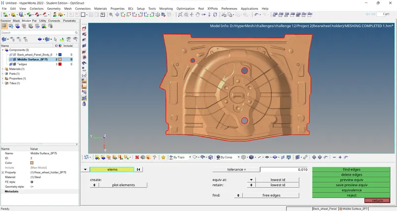
Figure: Free Edges Check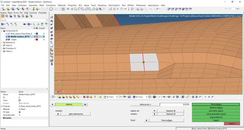
Figure: Correcting free edges using equivalence option - Check for Normal: The normal direction is checked by following the below steps,
Tools → Normals → display → we can choose colordisplay or vector display.
The defected element's normals are reversed using the same tool by selecting the element.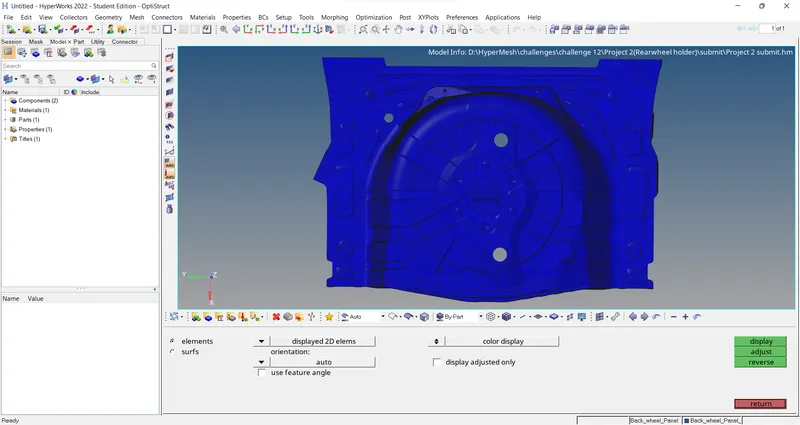
Figure: Normals check - Element to surface check: To check how the element is captured the surface geometry.
mesh → check → elements → comparison → click on element tab shown in source entity → Select element displayed → Proceed → click surface tab in the target entity → select surface displayed → Proceed → Tolerance = 0.2 → Run
The yellow and pink color in mesh is okay. If there is defect, we use project tool to rectify it.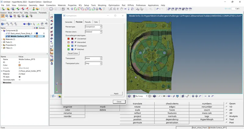
Figure: Elements to Surface Check - Penetration and intersection check: Penetration is defined as the overlap of the material thickness of shell elements, while intersection is defined as elements that actually pass completely through one another.
Tools → Penetration → select entities to be checked for penetrations or intersections → Choose all interferences → Select the type of elements to check → Select a method adjusting thickness → check.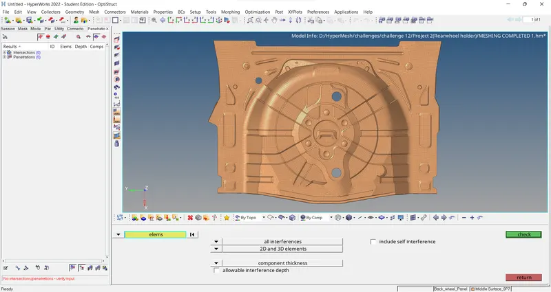
Figure: Penetration and intersections check
Step - 8: Assigning material and thickness
- The next step is to assign thickness to the model. The first step when assigning thickness is to measure the thickness at various spots in the model by using 'distance' tool.
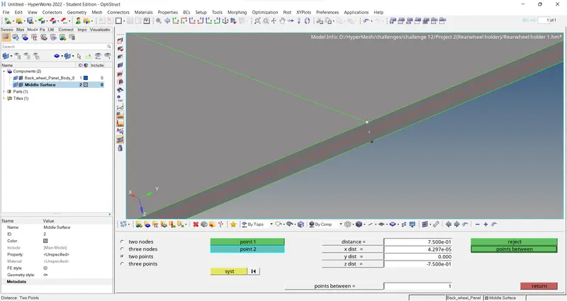
Figure: Measuring thickness - Before that we create a Material collector for the component.
Right click on component tab → Create → Material.
The material is given as Steel with card image as MAT1.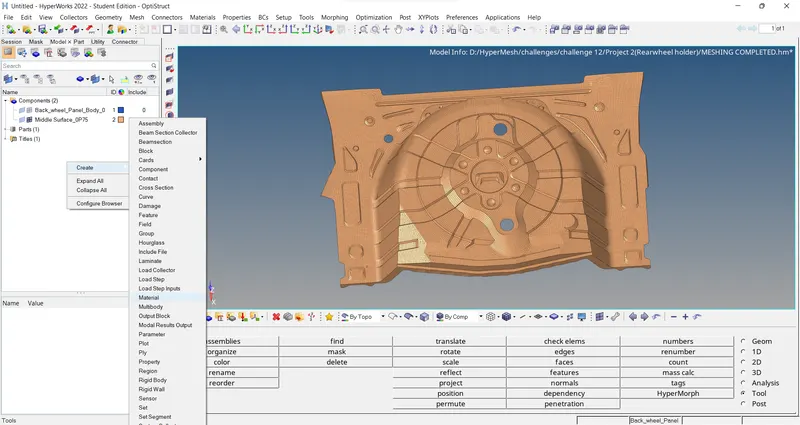
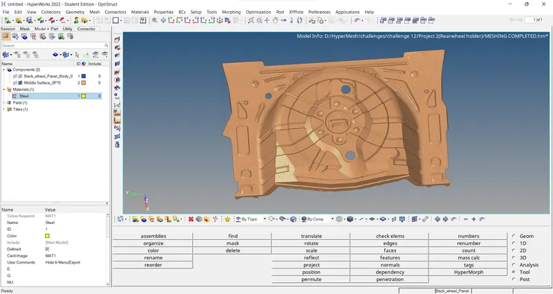
Figure: Creating Material - To assign proper thickness to the elements, we need to create a property and input the value of thickness for that property.
Right click on component tab → Create → Property.
Rename the property as Rear_wheel_holder_thickness.
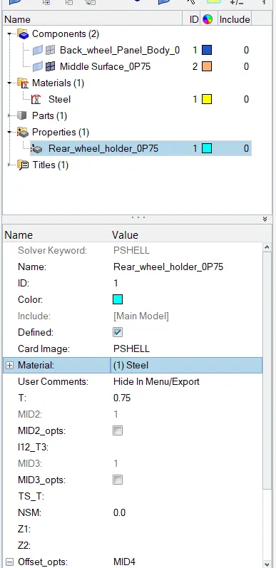
Figure: Creating property and inputing thickness and material to the property - Now we assign this material and property to our component collector i.e, Middle Surface_0P75
Right click on component collector → select the required property and material → Click OK.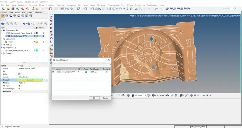
Figure: Assigning property and material to the component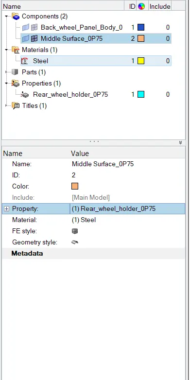
Figure: Component after assigning property and material - We can view the element as 2D detailed element representation or viewing element by thickness (From element color mode) to check whether the thickness is assigned or not.
5.Outputs:
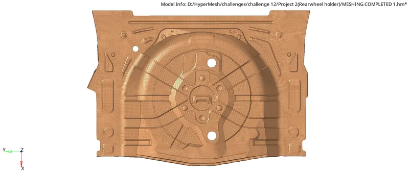
Figure: Final Meshed component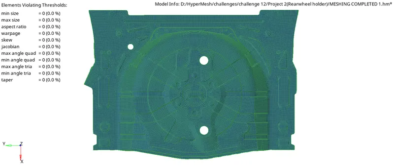
Figure: Qualityindex after error correction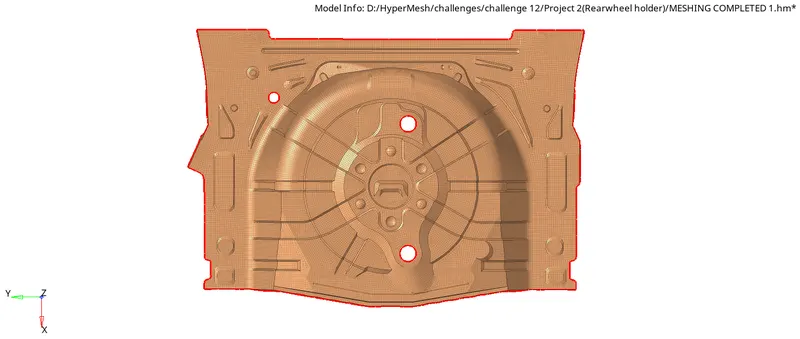
Figure: Free Edges Check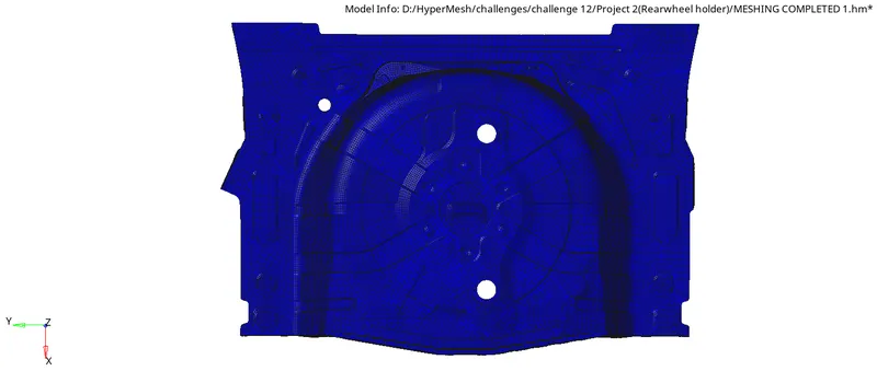
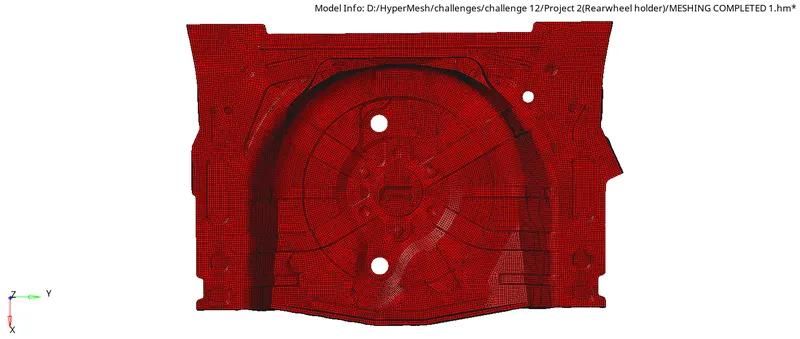
Figure: Normals check
6.Results:
- Extracted midsurface of the given sheetmetal component(rearwheel holder) using HyperWorks.
- Generated mesh on the midsurface as per the given quality criteria.
- Validated the meshed components against the given quality criteria using the "qualityindex" and various modal check options available in HyperMesh.
- Measured the thickness using distance tool and assigned material and thickness to the component.
7.Conclusions:
- This project helps us to have better understanding of tools and methods in Hypermesh for meshing and element quality correction.
- It also reminds us the importance of creating midsurface without any defects for getting proper mesh with quality and connectivity.
- This project provides better experience in manual geometry clean-up, handling trias at critical areas and element quality correction.