Week 1 Spur Gear Challenge
Spur Gear Challenge
1.Aim: To perform static structural analysis and find out Equivalent stress, Total deformation and Stress intensity on a pair of Spur Gears using different materials and compare their results.
2.Objective:
-
To perform static structural analysis and find out Equivalent stress, Total deformation and Stress intensity on a pair of Spur Gears using Cast Iron(ductile) as the material.
- To perform the same analysis using Cast Steel as the material.
- To perform the analysis using Cast Bronze as the material.
3.Theory:
i.Spur gears are the simplest type of gear. They consist of a cylinder or disk with teeth projecting radially. Though the teeth are not straight-sided (but usually of special form to achieve a constant drive ratio, mainly involute but less commonly cycloidal), the edge of each tooth is straight and aligned parallel to the axis of rotation. These gears mesh together correctly only if fitted to parallel shafts. No axial thrust is created by the tooth loads. Spur gears are excellent at moderate speeds but tend to be noisy at high speeds.
Spur gear teeth are manufactured by either involute profile or cycloidal profile. Most of the gears are manufactured by involute profile with 20° pressure angle. When two gears are in mesh at one instant there is a chance to mate involute portion with non-involute portion of mating gear. This phenomenon is known as "Interference" and occurs when the number of teeth on the smaller(pinion) of the two meshing gears is less than a required minimum. To avoid interference we can have undercutting, but this is not a suitable solution as undercutting leads to weakening of tooth at its base. In this situation Corrected gears are used. In corrected gears Cutter rack is shifted upwards or downwards.
The spur gears can be classified into two main categories: External and Internal. The gears with teeth cut outside of the cylinder are known as external gears. The gears with teeth cut on the internal side of the cylinder are known as internal gears. An external gear can mesh with an external gear or an internal gear. When two external gears mesh together they rotate in the opposite directions. An internal gear can only mesh with an external gear and the gears rotate in the same direction.
ii.Stress Intensity:
The stress intensity factor, , is used in fracture mechanics to predict the stress state ("stress intensity") near the tip of a crack or notch caused by a remote load or residual stresses. It is a theoretical construct usually applied to a homogeneous, linear elastic material and is useful for providing a failure criterion for brittle materials, and is a critical technique in the discipline of damage tolerance. The concept can also be applied to materials that exhibit small-scale yielding at a crack tip. The magnitude of stress intensity depends on specimen geometry, the size and location of the crack or notch, and the magnitude and the distribution of loads on the material. It can be written as:
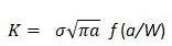
Where, f (a/W) is a specimen geometry dependent function of the crack length a, and the specimen width W, and `sigma` is the applied stress.
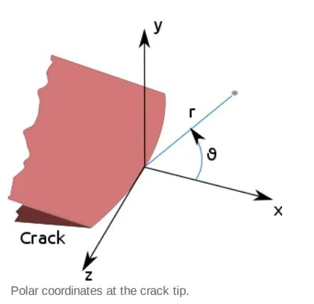
Linear elastic theory predicts that the stress distribution near the crack tip, in polar coordinates
 with origin at the crack tip, has the form as:

Where is the stress intensity factor (with units of stress length1/2) and fij is a dimensionless quantity that varies with the load and geometry. Theoretically, as goes to 0, the stress goes to
  resulting in a stress singularity. Practically however, this relation breaks down very close to the tip (small) because plasticity typically occurs at stresses exceeding the material's yield strength and the linear elastic solution is no longer applicable. Nonetheless, if the crack-tip plastic zone is small in comparison to the crack length, the asymptotic stress distribution near the crack tip is still applicable.
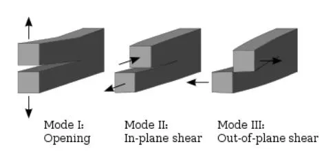
Stress Intensity Factors for various modes:In 1957, G. Irwin found that the stresses around a crack could be expressed in terms of a scaling factor called the stress intensity factor. He found that a crack subjected to any arbitrary loading could be resolved into three types of linearly independent cracking modes. These load types are categorized as Mode I, II, or III as shown in the figure.
- Mode I is an opening (tensile) mode,Where the crack surfaces move directly apart.
- Mode II is a sliding (in-plane shear) mode where the crack surfaces slide over one another in a direction perpendicular to the leading edge of the crack.
- Mode III is a tearing (antiplane shear) mode where the crack surfaces move relative to one another and parallel to the leading edge of the crack.Mode I is the most common load type encountered in engineering design.
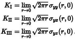
Different subscripts are used to designate the stress intensity factor for the three different modes. The stress intensity factor for mode I Is designated KI and applied to the crack opening mode. The mode KII stress intensity factor, , applies to the crack sliding mode and
The mode III stress intensity factor, KIII, applies to the tearing mode. These factors are formally defined as:
Example: Uniform uniaxial stress:
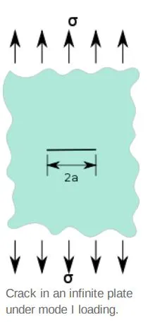
The stress intensity factor for an assumed straight crack of length 2a perpendicular to the
Loading direction, in an infinite plane, having a uniform stress field σ is

4.Procedure:
In this challenge, we will be carrying out Static Structural Analysis on a pair of Spur Gears with 3 different materials namely Ductile Cast Iron, Cast Steel and Cast Bronze. The case setup for Ductile Cat Iron will be discussed here and will be same for the rest of the materials.
- Open the ANSYS Workbench software. Under the Analysis system select the Static structural and wait for few seconds to pop up the window, which contains Engineering data, Geometry, Model, setup, Solution and Results.
- Rename the static structural as Spur Gear.
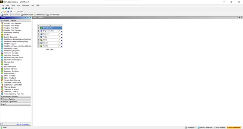
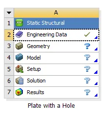
- Update the required material to the system, under the Engineering data. Since the required materials are not available in our data base we add them as a new material with their material properties as shown below:
Case 1: Cast Iron(Ductile)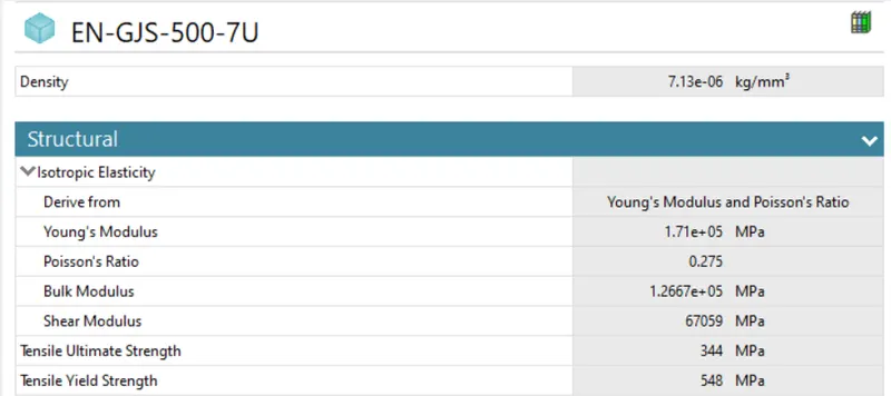
Case 2: Cast Steel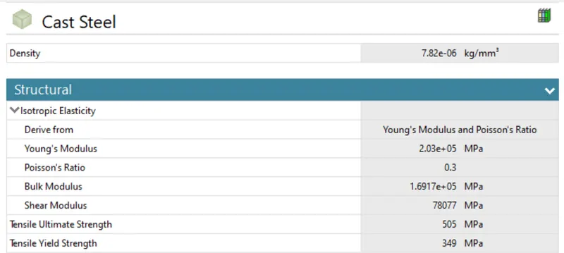
Case 3: Cast Bronze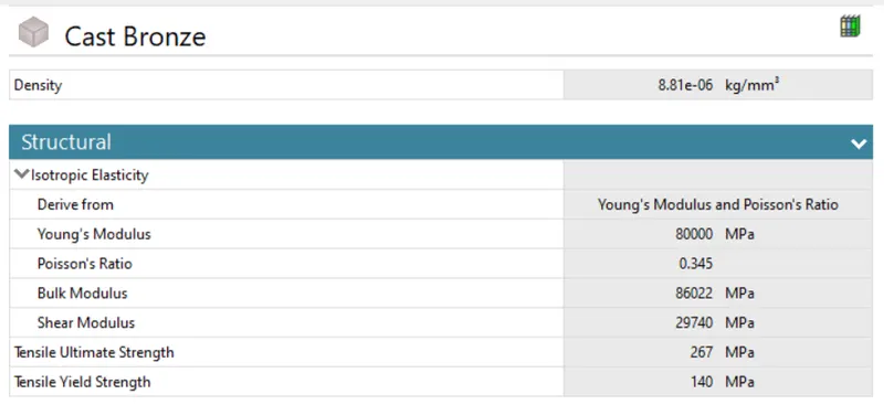
- Import the given geometry into design modeller.The spur gear has 13 teeth with driver gear being named as right gear and driven gear being named as left gear.
- Now we need to define contact between the pair of spur gers. For this we use Frictional Contact with the following details:
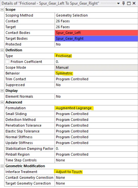
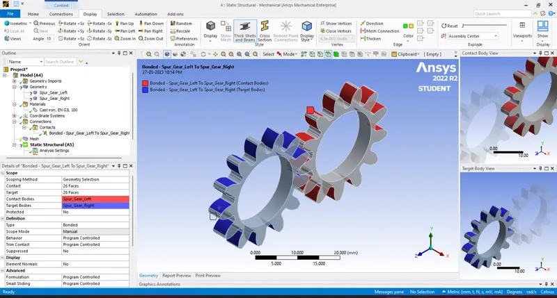
Select Contact type = Frictional. Because due to friction, there will be movement between gears.
Select Behavior = Symmetric
Select Formulation = Augmented Lagrange. As soon as teeth come in contact, it will tend to move from its position. So, Augmented Lagrange formulation reduces vibration and penetration and increases stiffness of gears.
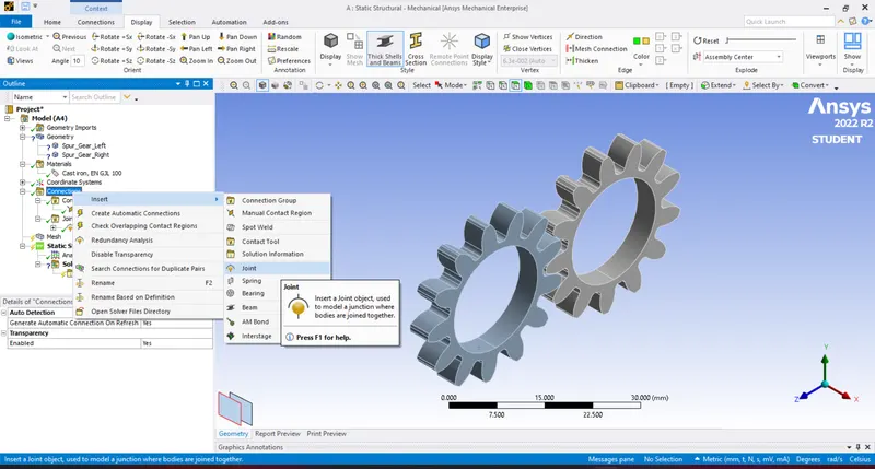
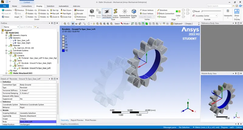
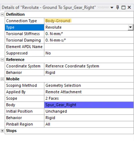
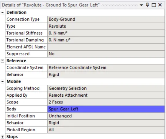
Select Interface Treatment = Adjust to Touch. Because if there is a gap between them or initial penetration, then this setting will help to adjust it and any error can be avoided. - After creation of connection between gears, create joints. Select inner face of each gear and give it a Revolute Joint as described in the image.For frame of reference for gears, select Connection Type = Body to Ground for both of the gears.We can see that in revolute joint, degree of freedom for gears automatically set to its axis or in RZ direction.
-
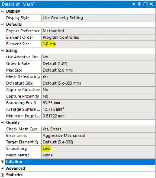
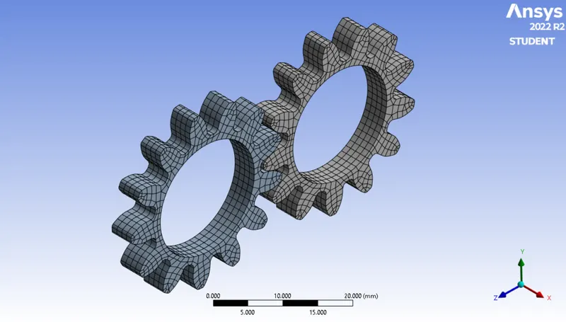
Meshing: Create a 2D mixed mesh using the default mesh size(i.e. 1mm)
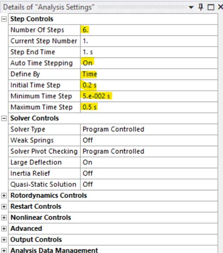
- Boundary conditions: Here we are going to look at contact forces, traces and stress developed for 1 revolution of gear. So for 180 degree angle , In analysis settings give values as given below:
No. of Steps = 6
Auto Time stepping = ON
Defined by = Time
Initial Time Step = 0.2
Minimum Time Step = 0.05 s
Maximum Time Step = 0.5 s
Select all 6 steps and select “Large Deflection = ON” in solver controls.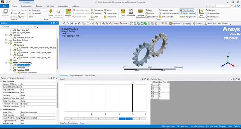
Other Boundary conditions for joints are as given below:
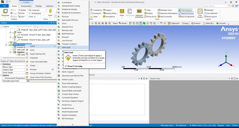
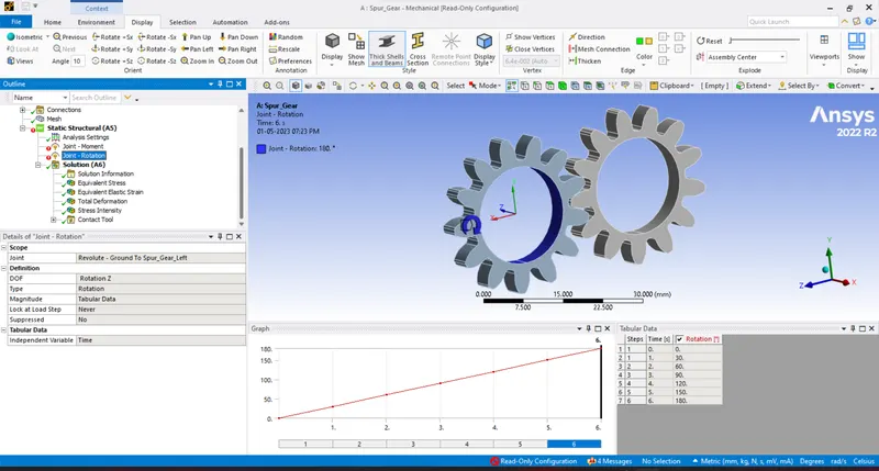
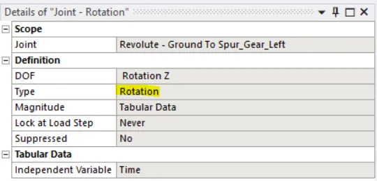
Joint Load :
Joint: Revolute – Ground to Spur_Gear_LeftType: Rotation
Magnitude: Tabular Data
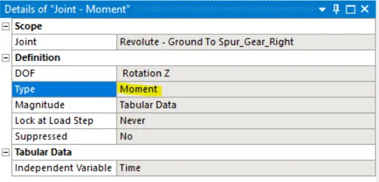
For pionion(driver), we give the Type as Moment.Joint Load :
Joint: Revolute – Ground to Spur_Gear_RightType: Moment
Magnitude: Tabular Data
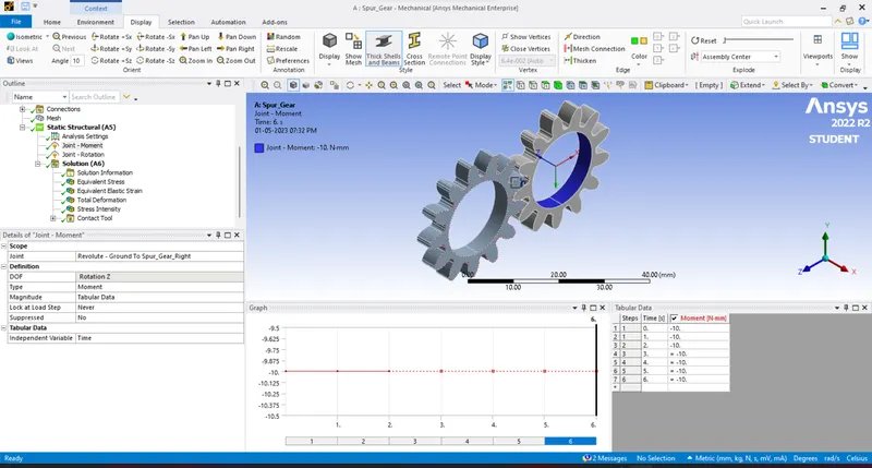
The left gear is the driven gear hence, rotation (clockwise) for 1800 is specified with an increment value of 300 for each step.
The right gear is the driver gear hence, moment (anti-clockwise) of -10 N-m is specified for all the steps.
-
Solution:After giving proper boundary conditions, create desired solutions for output results.
Create Solutions for “Equivalent (Von Mises) Stress", “Equivalent (Von Mises) Strain",“Total Deformation” and for “Stress Intensity”.
Also give Contact Tool and create solutions for contact “Status” and “Pressure”.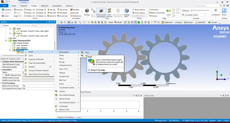
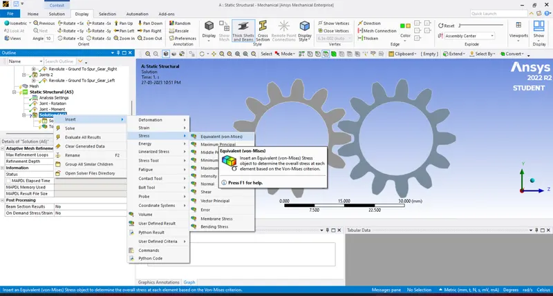
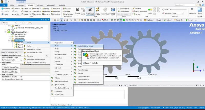

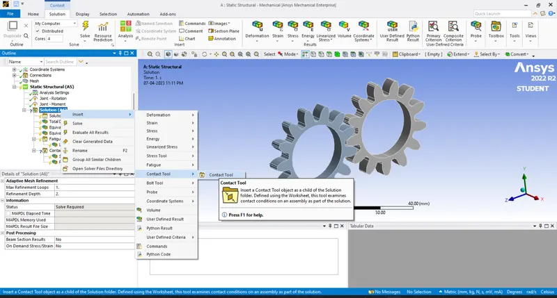
Finally evaluate all the results.
6.Results and Observations:
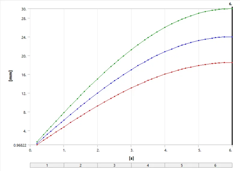
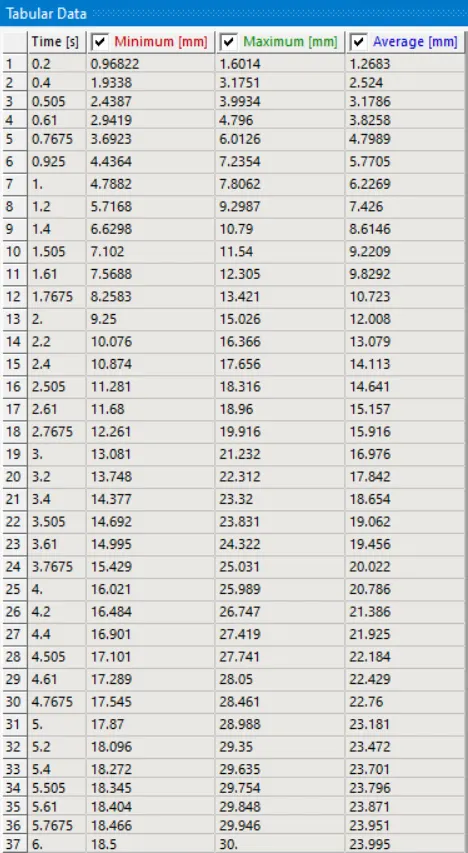
6.1 Total Deformation:
Case-1: Cast Iron(Ductile)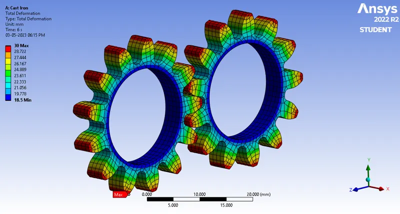
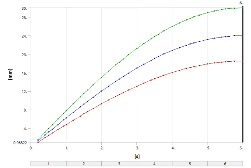
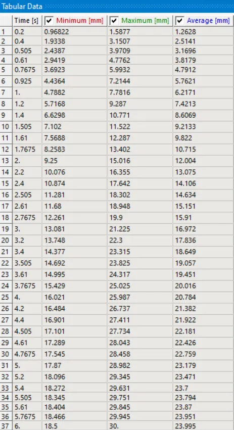
Case-2: Cast Steel: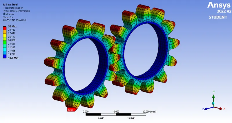
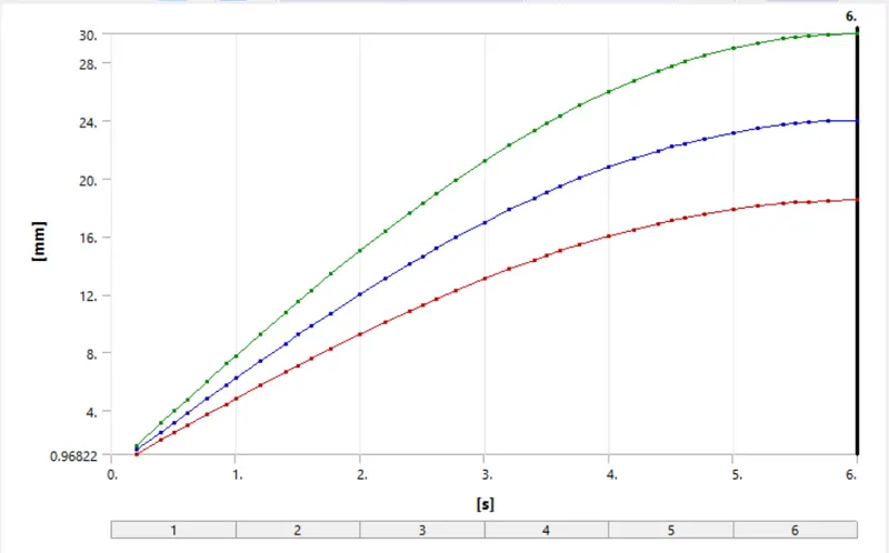
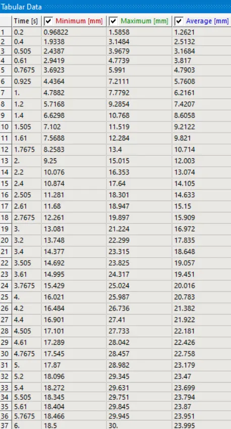
Case-3: Cast Bronze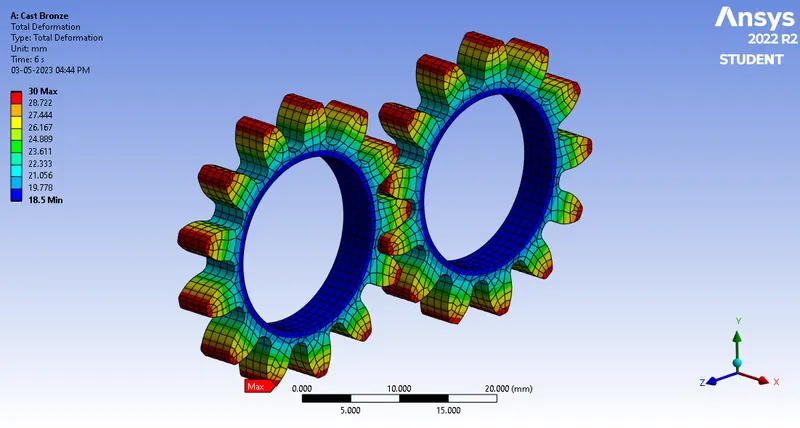
6.2 Equivalent stress distribution:
Case-1: Cast Iron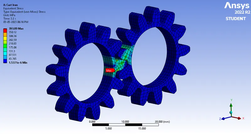
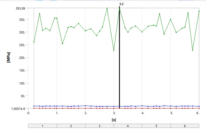
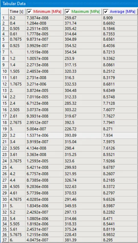
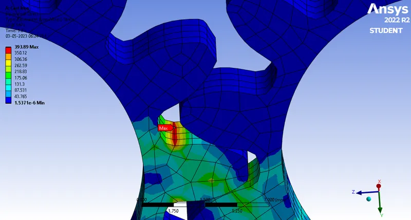
The above image shows the region of maximum stress which is more prone to failure.
Case-2: Cast Steel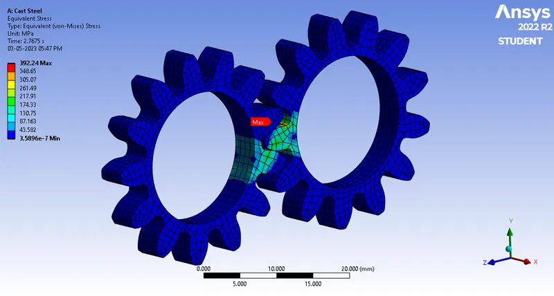
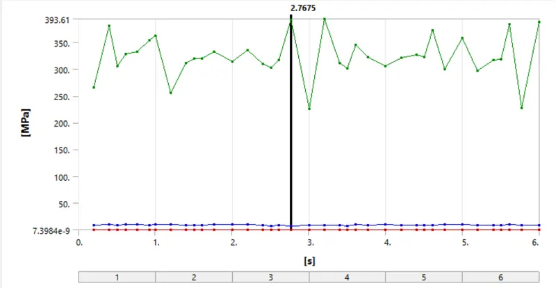
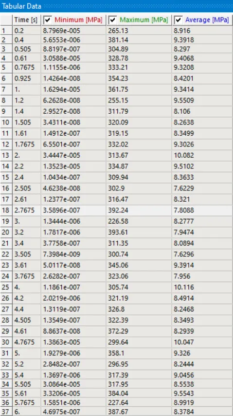
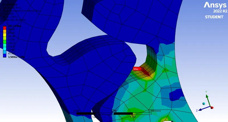
The above image shows the region of maximum stress which is more prone to failure.
Case-3: Cast Bronze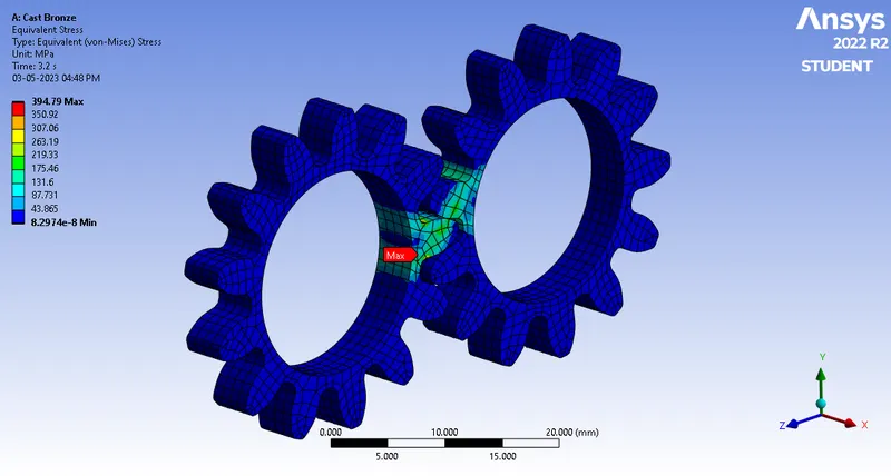
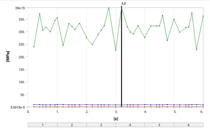
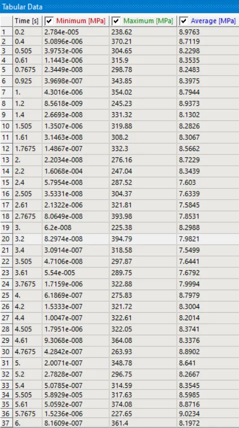
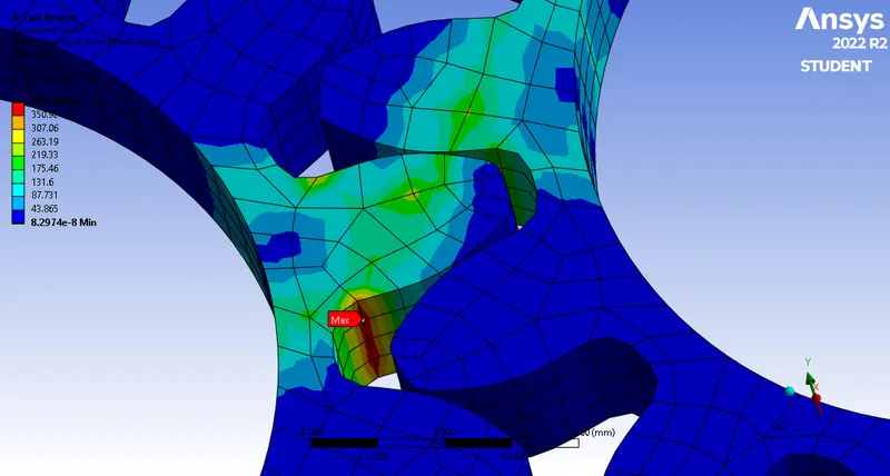
The above image shows the region of maximum stress which is more prone to failure.
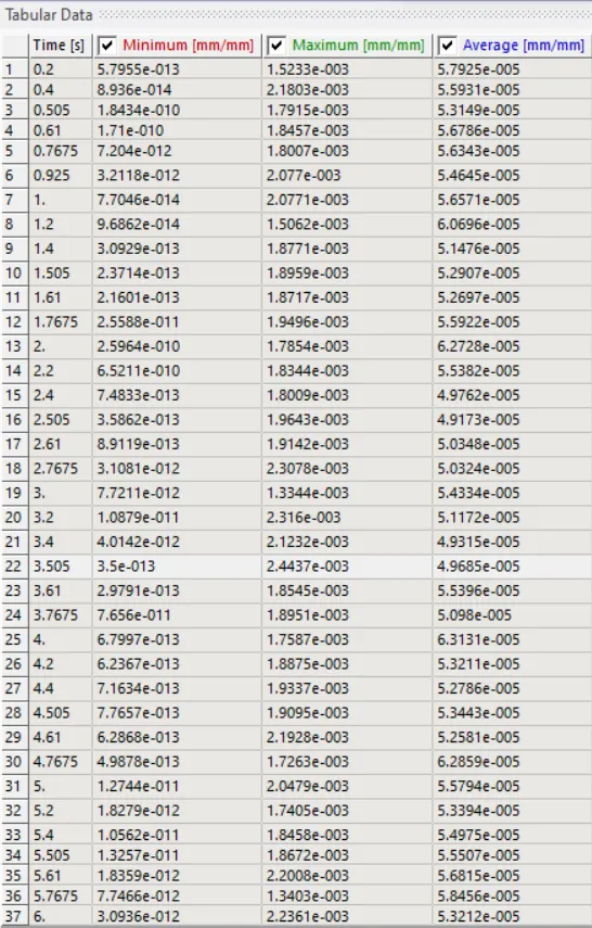
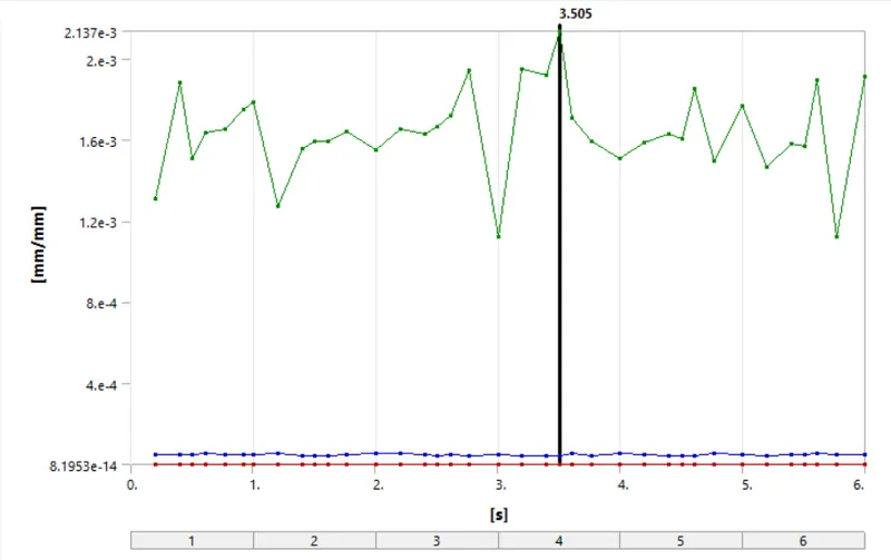
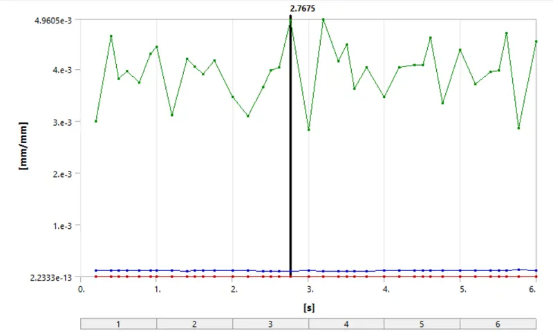
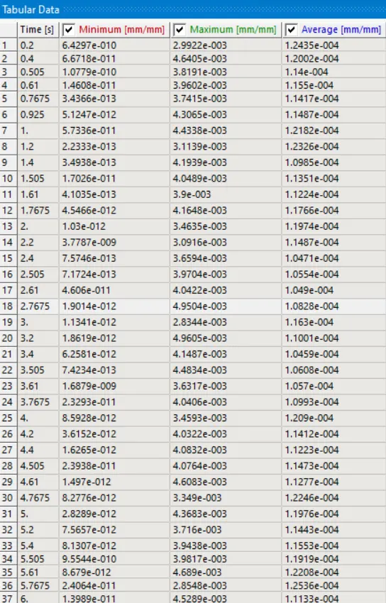
6.3 Equivalent strain distribution:
Case-1: Cast Iron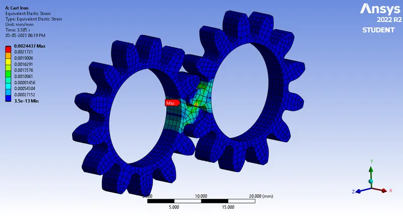
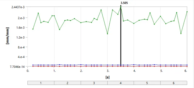
Case-2: Cast Steel: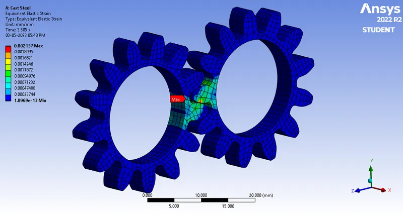
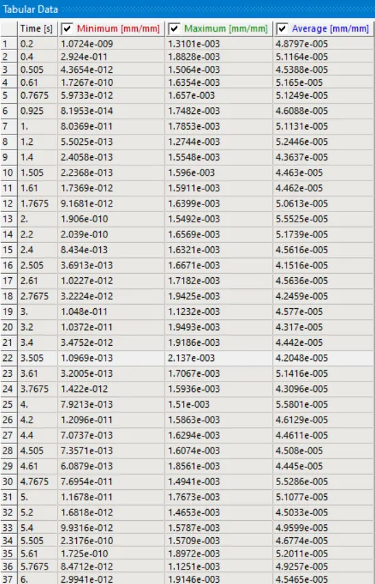
Case-3: Cast Bronze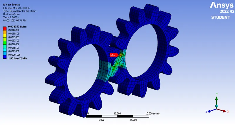
6.4 Stress Intensity:
Case-1: Cast Iron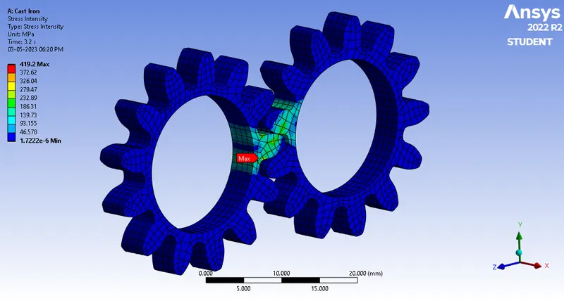
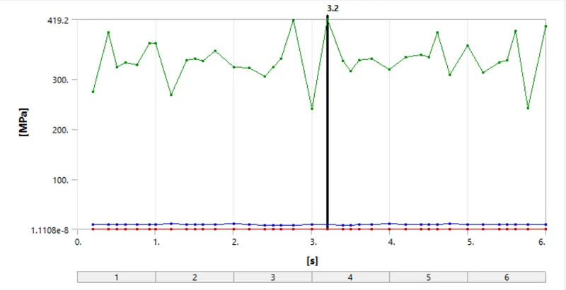
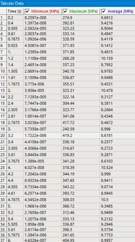
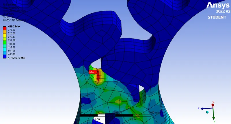
The above image shows the region of maximum stress intensity which is more prone to fracture/failure.
Case-2: Cast Steel: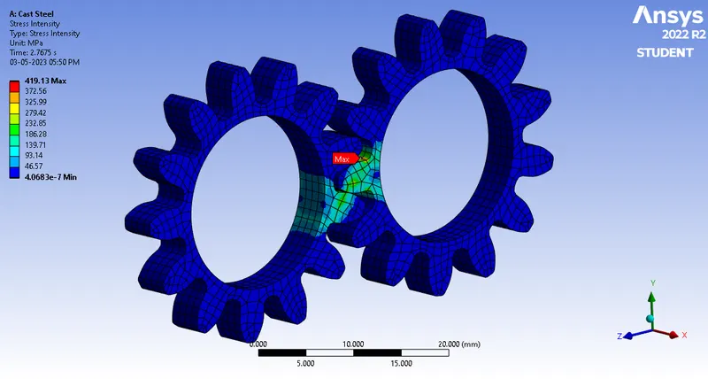
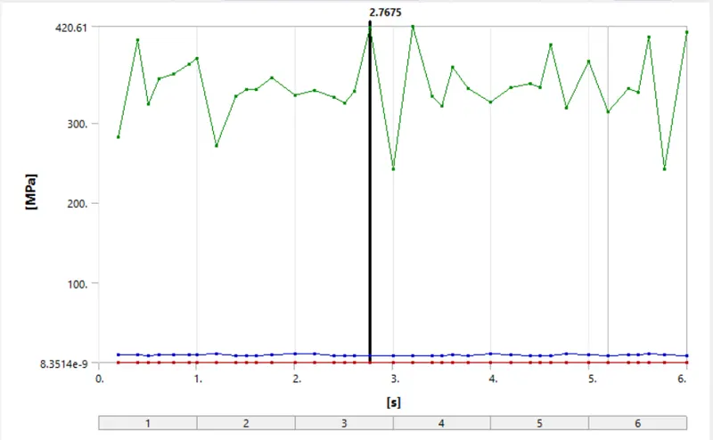
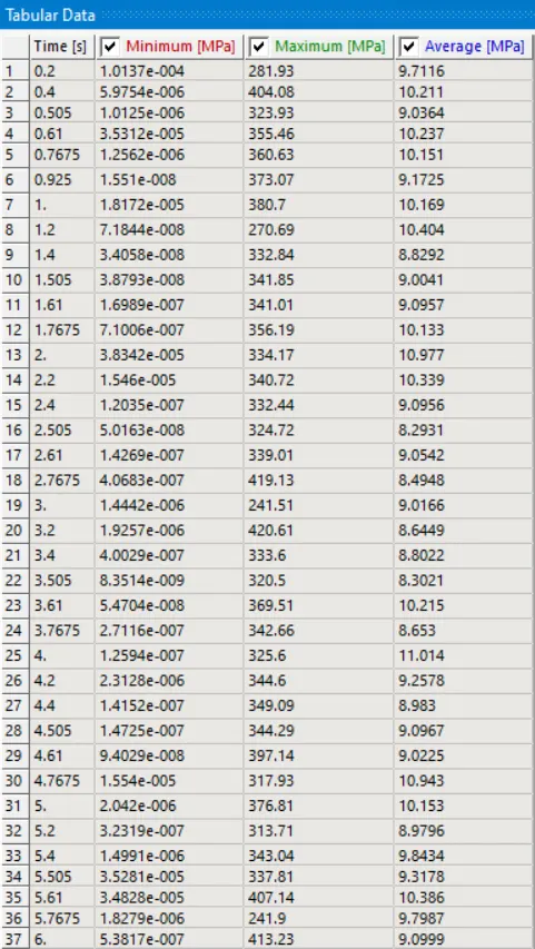
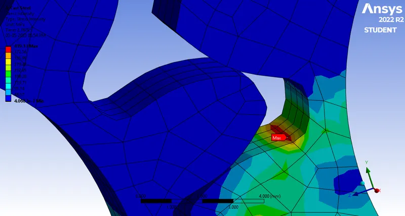
The above image shows the region of maximum stress intensity which is more prone to fracture/failure.
Case-3: Cast Bronze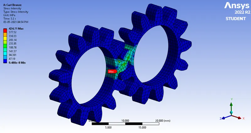
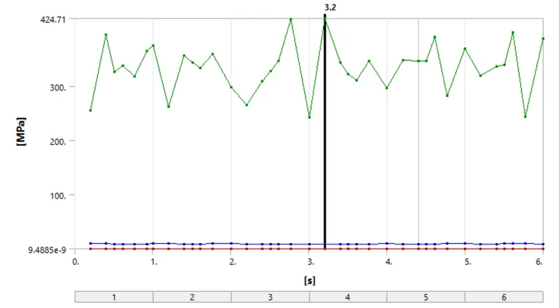
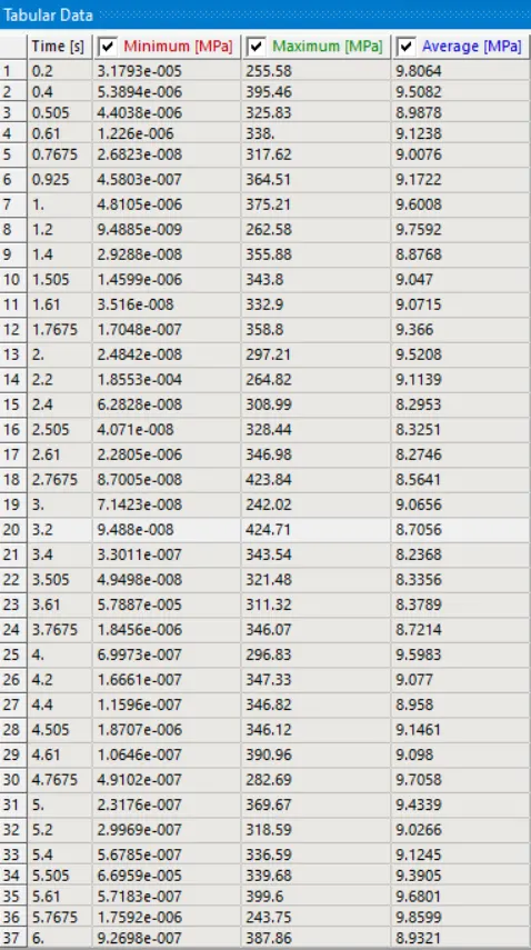
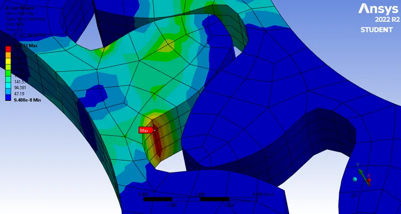
The above image shows the region of maximum stress intensity which is more prone to fracture/failure.
6.5 Contacts :
6.5.1 Contacts Status:
Case-1: Cast Iron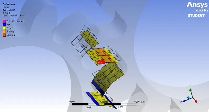
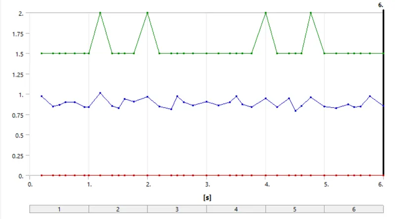
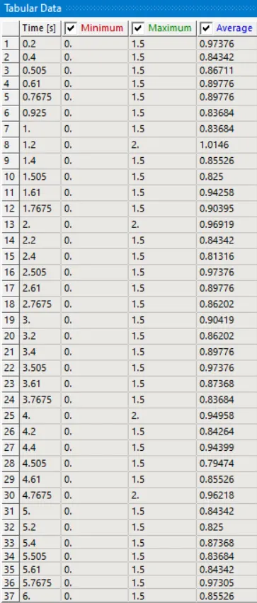
Case-2: Cast Steel: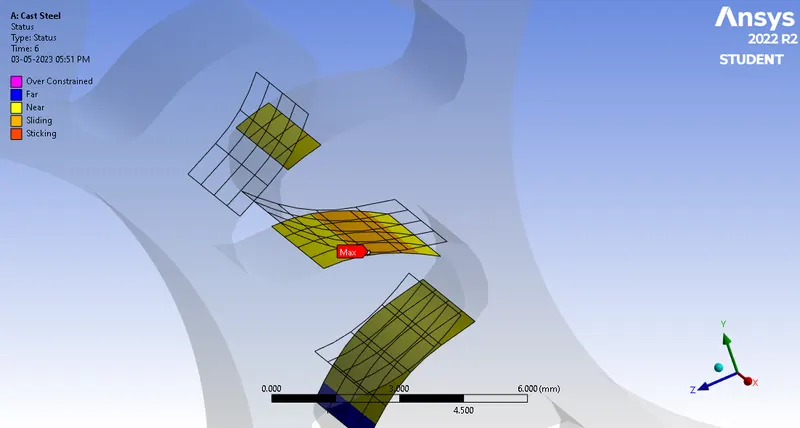
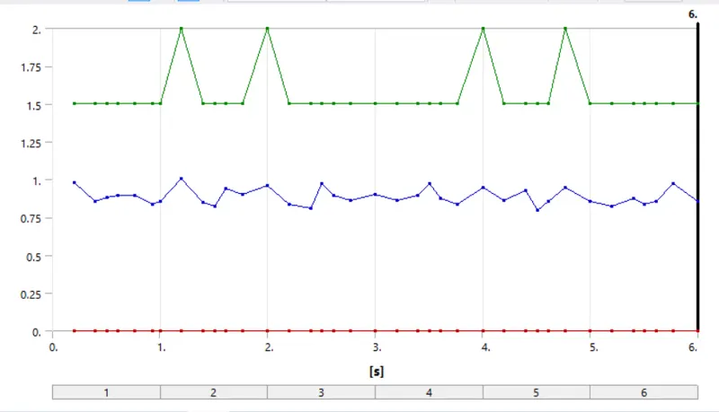
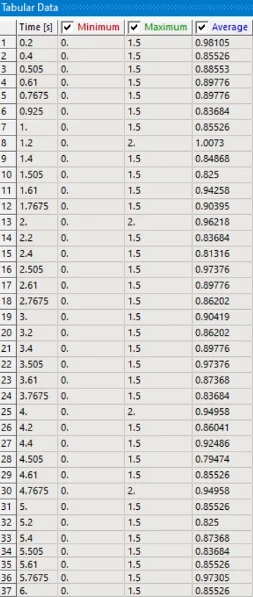
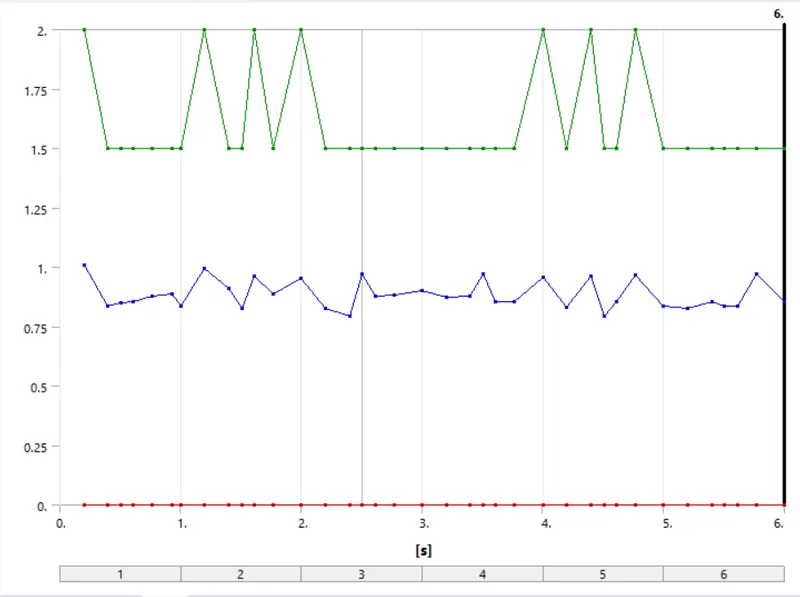
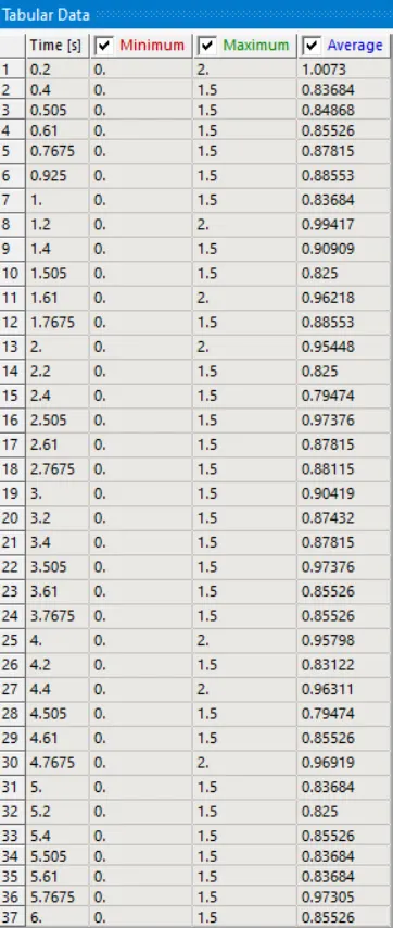
Case-3: Cast Bronze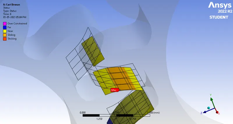
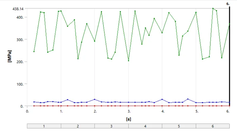
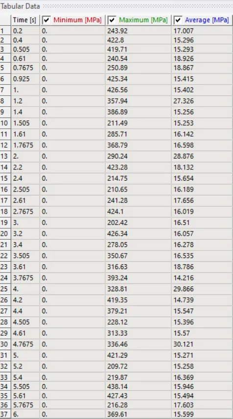
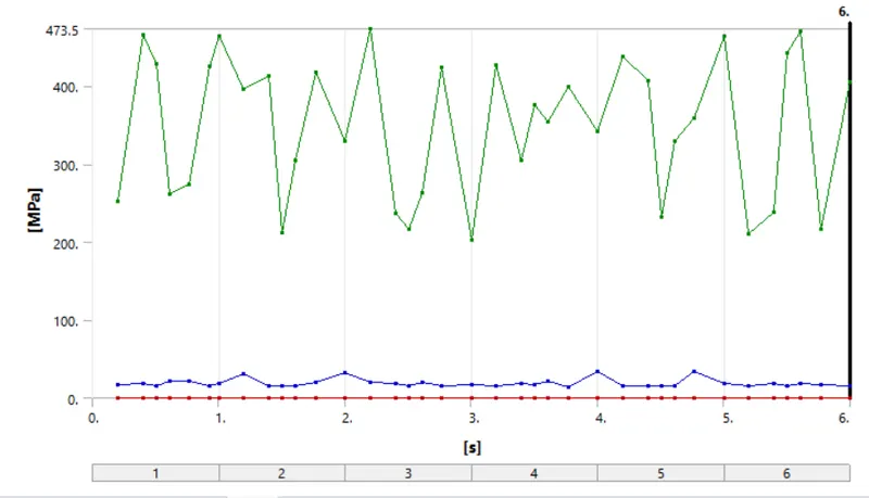
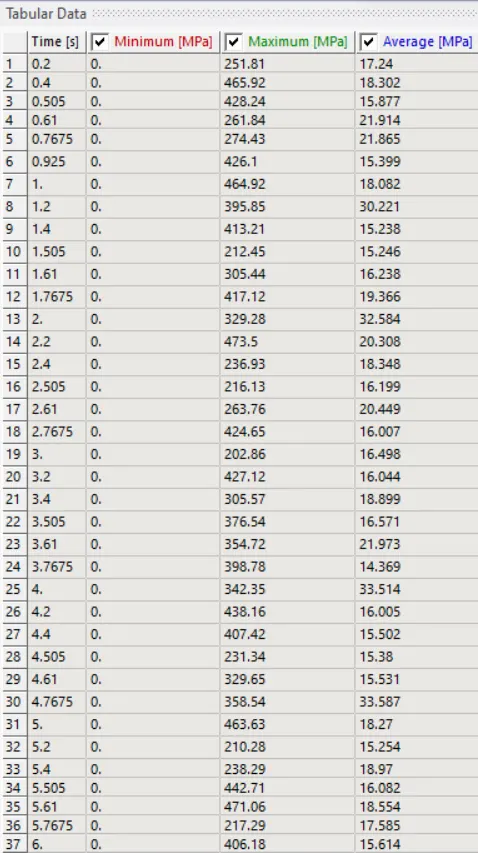
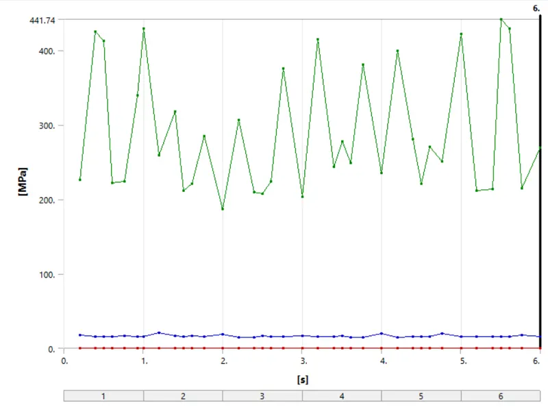
6.5.2 Contacts Pressure:
Case-1: Cast Iron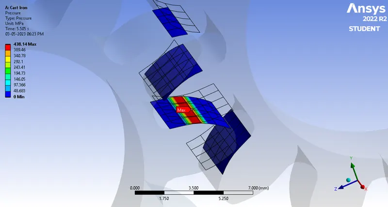
Case-2: Cast Steel: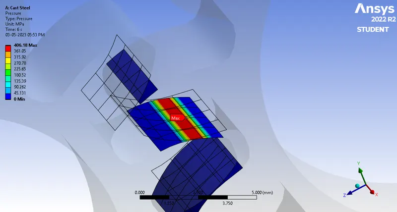
Case-3: Cast Bronze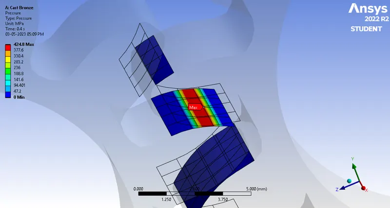
7.Conclusions:
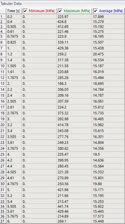
The maximum and minimum values of total deformation, Von-Mises stress and stress intensity is tabulated as shown below.
|
Materials |
Total Deformation (mm) |
Equivalent Stress (MPa) |
Stress Intensity (MPa) |
|||
|
Max. |
Min. |
Max. |
Min. |
Max. |
Min. |
|
|
Case-1: Cast Iron |
30 |
18.5 |
393.89 |
1.5371e-6 |
419.20 |
1.7222e-6 |
|
Case-2: Cast Steel |
30 |
18.5 |
392.24 |
3.5896e-7 |
419.13 |
4.0683e-7 |
|
Case-3: Cast Bronze |
30 |
18.5 |
394.79 |
8.2974e-8 |
424.71 |
9.488e-8 |
Eventhough all the three materials are giving results in comparable ranges, from the above table it is evident that the max stress and stress intensity values occur for Cast Bronze. Hence, it is the least preferred material for making the gear pair. If we look at the values for Cast steel, we can find that the analysis gives min values for Cast Steel as the material.
Hence, the choice of material would be as follows:
1.Cast Steel
2.Cast Iron
3.Cast Bronze
for both traditional Strength of Materials approach and Fracture Mechanics approach.