Week 9-Creation of 1D Connectors Challenge
Creation of 1D Connectors Challenge
1.Aim: To mesh the geometry as per the given quality parameters, create connectors and attach the various components of the model using HyperWorks.
2.Objectives:
- To mesh the given geometry as per the required quality parameters using HyperWorks.
Target Element size - 5 Units
S.N
Quality Criteria
Value
1
Aspect Ratio
5
2
Skewness
45
3
Warping
15
4
Taper
0.5
5
Min. Length
2 Units
6
Max. Length
8 Units
7
Min angle Quad
45
8
Max angle Quad
135
9
Min angle Tria
30
10
Max angle Tria
110
10
Tria %
15
- To create suitable connectors and connect the various components of the given model as per requirement.
1. Right_Rail_2 & Front_truss_1:- Seam-Quad(angled+capped+L)
2. Left_Rail_2 & Front_truss_1:- Quad elements
3. Front_truss_2, Front_truss_1 & Right_Rail_1:- Spot weld with 2 Layers and 5 mm Diameter
4. Front_truss_2, Front_truss_1 & Left_Rail_1:- Hexa (Adhesive)
5. Rear_truss_2 & Right_Rail_2:- Bolt Connector
6. Rear_truss_2 & Left_Rail_2:- Bolt Connector
7. Right_Rail_1 & Right_Rail_2:- Spot-weld with Rigid Elements
8. Left_Rail_1 & Left_Rail_2:- Spot-weld with Spring Elements
9. Rest all the component left Join them with suitable connectors
3.Theory:
Connectors are geometric entities (not FE) primarily used to create spot and seam welds, but also used to create adhesives, bolts and masses. They are simply a database of information defining specific requests for connections at specific locations.They are a medium to create both solver independent and/or solver dependent connections between geometric and/or FE entities. They can be created interactively or from different master connection files (.xml, .mcf, .vip).
Types of Connectors:
- Spot:
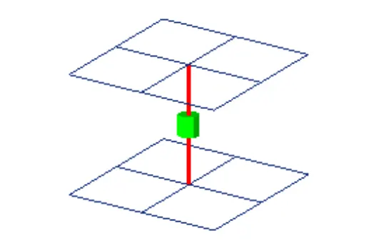
Connections at a point. Spot welds, rivets, etc. - Bolt:
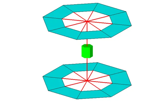
Connections at hole locations. - Trim Mass:
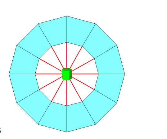
Non-physical mass. Simplification through replacement of parts with mass only or add mass to existing part. - Seam:
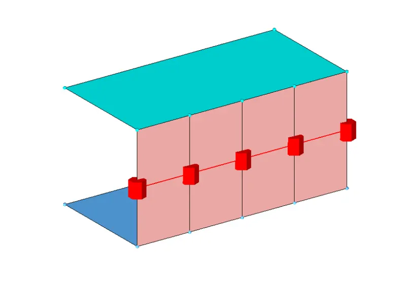
Connections along a length.
Seam welds.
Connects geometry only. - Area:
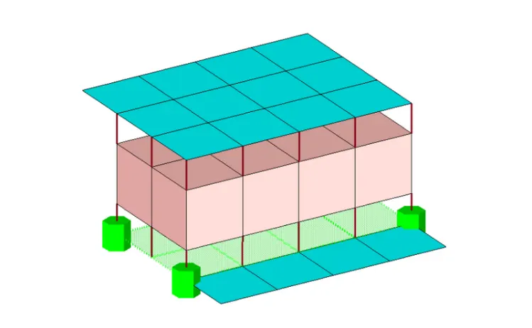
Connection of areas.
Adhesives.
Connectors: Terminology
- Link Entities - The entities that are being connected.
User can explicitly define link entities or specify a search tolerance
Can be components, elements, surfaces, nodes, or tags
Typically components are linked. - Connector Location - Where the entities are linked
Nodes – created at the node location
Points – created at the point location
Lines – created for the line. line may be split into multiple projection locations as specified by the offset, spacing, and density values
Elements – created at the element location (adhesives only)
Surface – created at the surface location (adhesives only) - Connector Realization – The creation of the finite element representation of that connector
Rigids, springs, etc., or custom configurations such as ACMs, CWELDS, etc. - Connector's Module -

1D Page → connectors
- Spot
- Bolt
- Seam
- Area
[create, edit, and realize that style of connectors.] - Apply Mass – adds a mass value to entities.Used to represent mass of parts that are not present in the model.
- FE Absorb – Create new connectors from existing elements of recognizable FE representations of welds, bolts, adhesives, etc.
- Add Links – Add link entities to existing connectors.
- Unrealize – Delete FE representations of welds / bolts / adhesives associated with existing connectors.
- Compare – Checks the MCF against displayed model file.
- Quality – Check for duplicate connectors, combine connectors, check quality of realized elements.
- Connector State –
Whether an FE representation of a connector has been created.
- Unrealized - The initial status of the connector entity upon creation.
Newly created or imported connector before the first realization. Editing the connector definition (i.e. add or delete a link entity from the connector), the connector removes the welds it created, and reverts back to an unrealized state. Manual unrealization.
- Realized - The status only if creation of the FE weld representation at the connector was successful.
- Failed – The status if the creating the FE weld representation at the connector was not successful.
If the creation of the FE representation is unsuccessful (due to low tolerance, insufficient link entities, etc.) the connector icon is displayed as failed (red).
4.Procedure:
Step 1: Importing the geometry
- To import the geometry, go to file → Import → Import Solver Deck→ File Type: Optistruct → File: frame_assembly_welding.hm → Import.
The CAD model image is shown below with the subcomponents highlighted in different colours.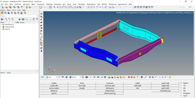
- After importing the geometry, the geometry is checked for any missing surfaces or any other errors and then correct it.
- The given components are already midsurfaces or are lacking thickness, so there is no need to create midsurfaces.
Step 2: Setting the Criteria and Topology cleanup
- We input the given criteria into the HyperWorks software for the respective model using the options
Preferences → criteria file settings and Preferences → parameter file settings.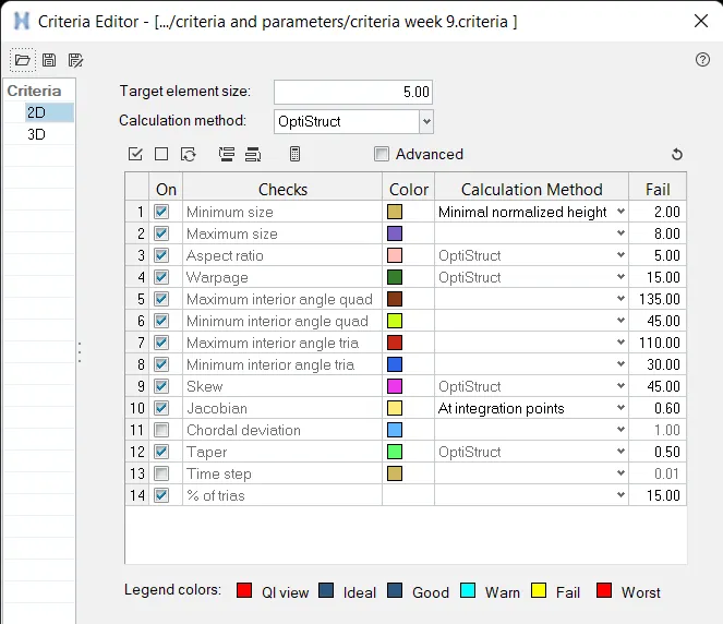
Figure: Criteria file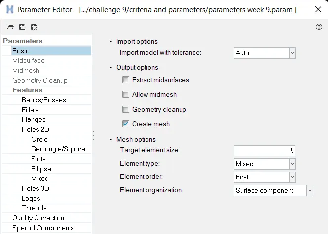
Figure: Parameter file
We also save them to be used later, if required. - Then we remove the solids using the option delete → Solid → Select solid → delete entity.
- Prior to meshing we do Geometry or Topology Clean-up in which we check for any free lines, unfilled surfaces and other errors.
- Toggle the unwanted lines(other than Feature lines) for better meshing.
- Remove the surface fillets having maximum radius less than the minimum mesh length using the option defeature → surf fillets → select the surfaces → min radius=0.1, max radius= min mesh length → find → delete.
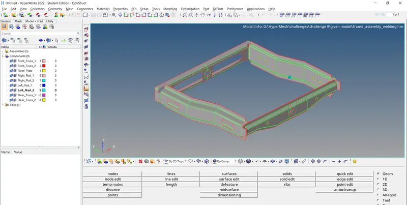
Figure: Model after Topology clean-up
Step 3: Meshing
- There are two ways by which we can generate mesh on the given model. First one, is to select all the components and mesh them at once.We can do it by the batchmesh option in 2D panel.
2D → automesh → Batchmesh/QI optimize → select criteria as well as parameter file saved → Select surface → mesh.
However, this may consume quite a bit of time depending upon the system specifications.
The second method is exactly the same but here we will be batchmeshing each component separately so as to reduce the load on the computer. I have chosen the latter. - I batchmeshed each component separately and corrected the quality deviations(if any) along with it.
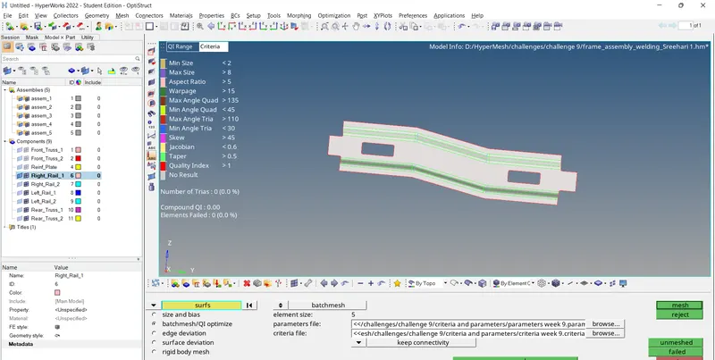
Figure: Right_Rail_1 before mesh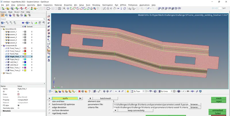
Figure: Right_Rail_1 after mesh - For symmetric components,we can also mesh the half portion and then reflect the mesh on to the other half.
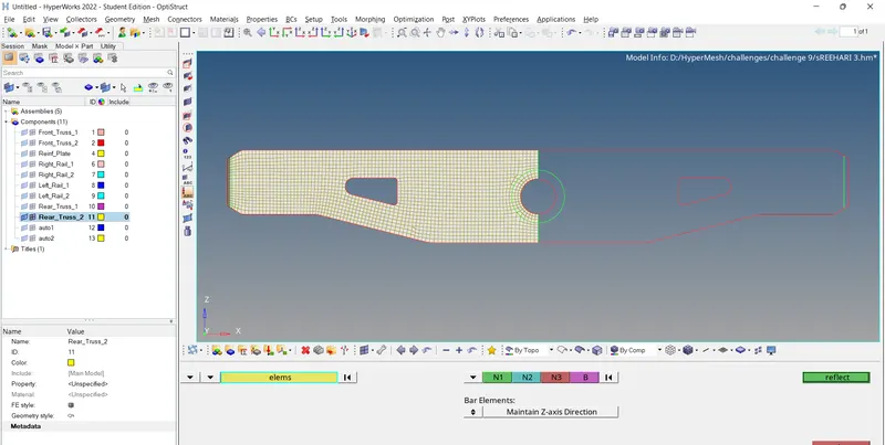
Figure: Reflecting the mesh on Rear_Truss_2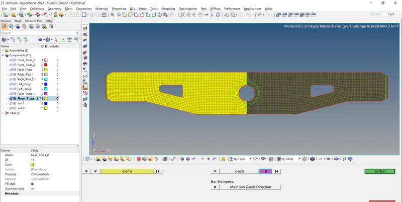
Figure: Reflected mesh on Rear_Truss_2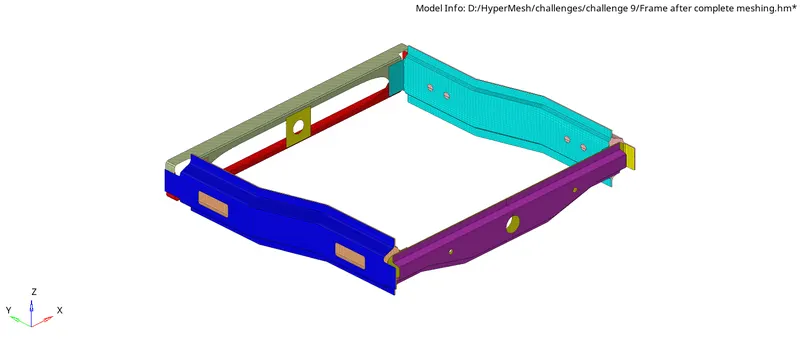
Figure: Final meshed model
Step 4: Quality checking
- Once after completing the mesh we need to check and ensure that the mesh so generated is as per the given quality criteria.
- For this we use the option 2D → qualityindex as well as Tool → check elems. There might be deviations in some or all of the quality criteria which we need to correct by using the various options available in the cleanup tool options available in the qualityindex.

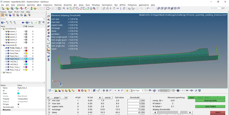
Figure: Deviations in qualityindex for Front_Truss_1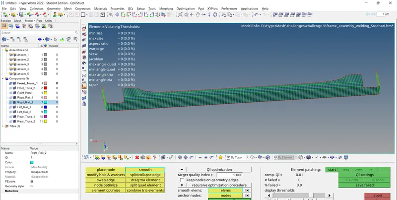
Figure: Corrected qualityindex for Front_Truss_1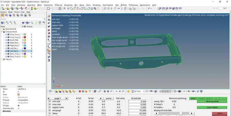
Figure:qualityindex after correcting all errors
Step 5: Creating 1D Connectors
- This is the most important step as far as this challenge is concerned.In this challenge,we are given a frame in which there are no connection among the components.Hence,after generating the mesh, we need to connect them using the 1D connectors as specified in the question.
1.Right_Rail_2 & Front_truss_1:- Seam-Quad(angled+capped+L)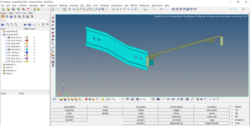
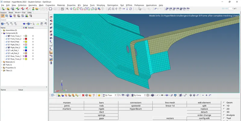
Figure:Right_Rail_2 & Front_truss_1 without connectors
To create a Seam-Quad(angled+capped+L) connector between the components, use the option
1D → connectors → seam → choose type: seam-quad(angled+capped+L), location: node path, spacing= Target element size, select components, weld angle=45, cap angle=60, use avg mesh size to imprint → create
Choose the tolerance value as per requirement.
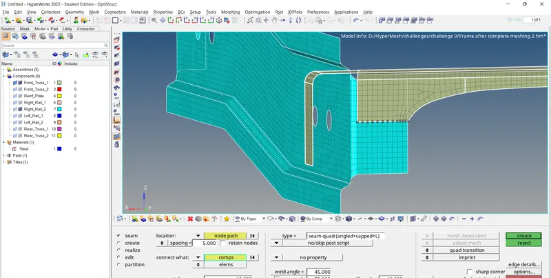
Figure: Creating connector
Since, we have chosen "imprint" the resulting connector may disrupt the mesh flow, which we need to correct manually.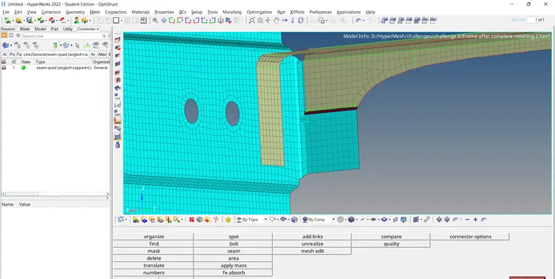
Figure: Connector causing disturbance in mesh flow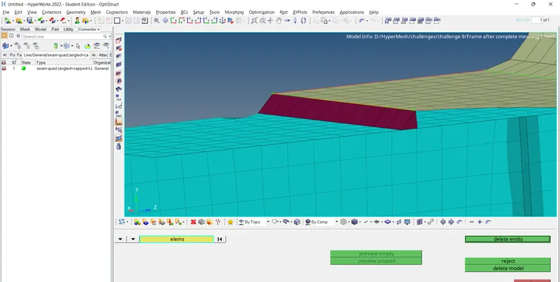
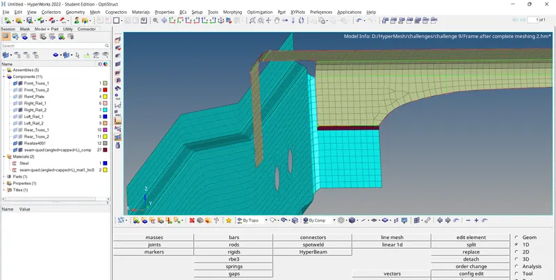
Figure: Connector after correcting the mesh flow
2. Left_Rail_2 & Front_truss_1:- Quad elements
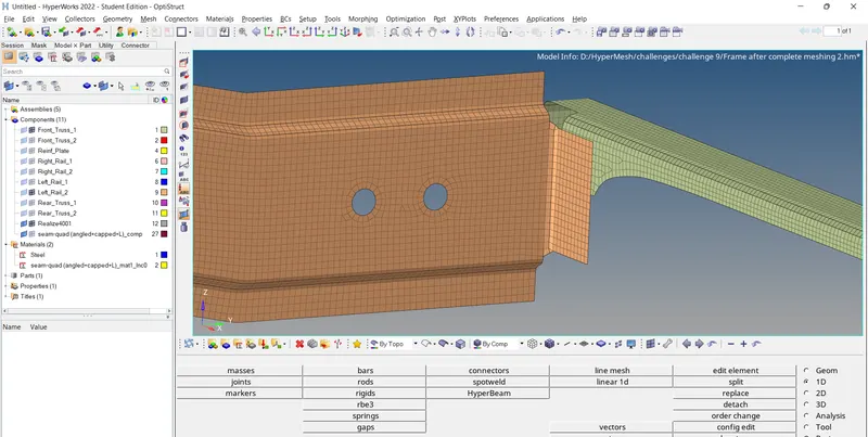
Figure: Left_Rail_2 & Front_truss_1 without connectors
To create a Quad connector between the components, use the option
1D → connectors → seam → choose type: quads, location: node path, spacing= Target element size, select components, use avg mesh size to imprint → create

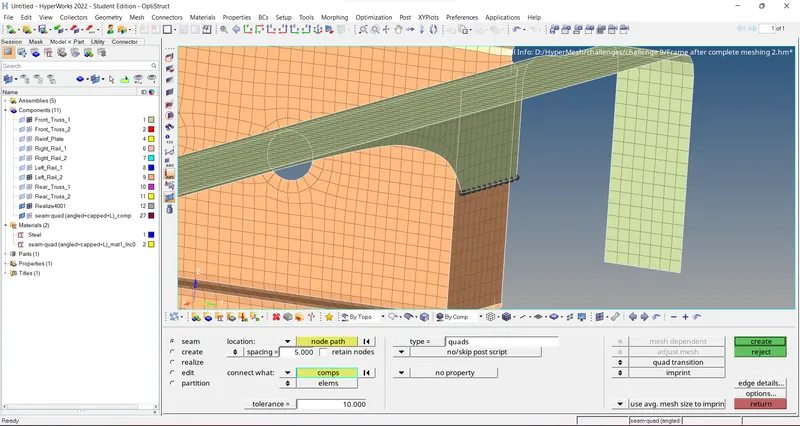
Figure: Creating connector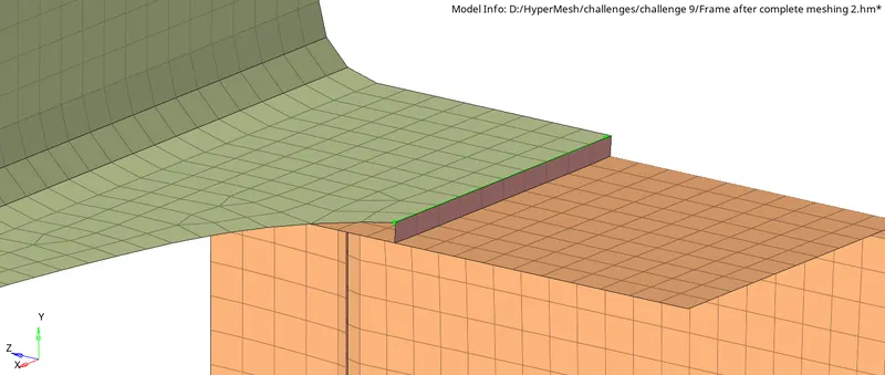
Figure: Left_Rail_2 & Front_truss_1 with connector after correcting meshflow
3. Front_truss_2, Front_truss_1 & Right_Rail_1:- Spot weld with 2 Layers and 5 mm Diameter
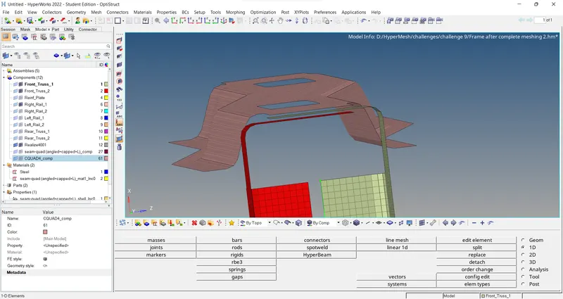
Figure: Front_truss_2, Front_truss_1 & Right_Rail_1 without connectors
To create Spot weld with 2 Layers and 5 mm Diameter among the components, use the option
1D → connectors → spot → choose type: weld, location: nodes, select components, num Layers: total 2, diameter 5 → create
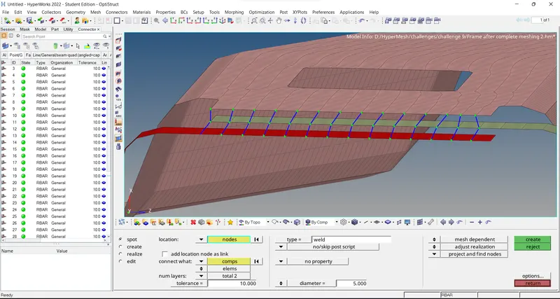
Figure: Front_truss_2, Front_truss_1 & Right_Rail_1 after spot weld
4. Front_truss_2, Front_truss_1 & Left_Rail_1:- Hexa (Adhesive)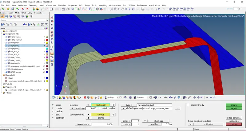
Figure: Front_truss_2, Front_truss_1 & Left_Rail_1 without connector
To create a Hexa(adhesive) among the components, use the option
1D → connectors → seam → choose type: hexa(adhesive), location: node path, spacing= Target element size, select components → create

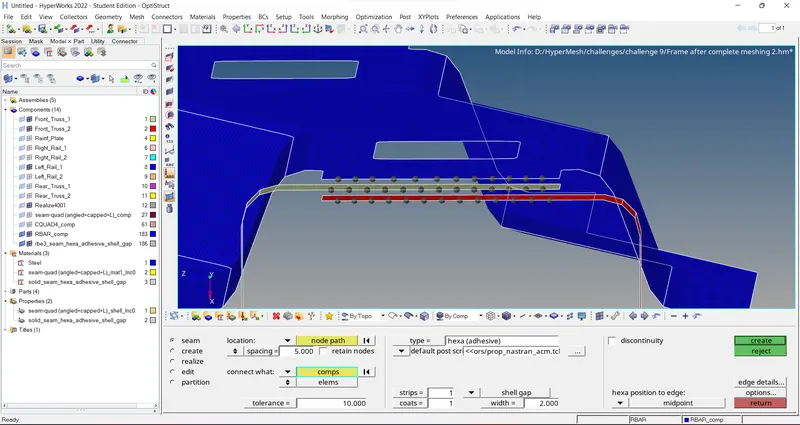
Figure: Front_truss_2, Front_truss_1 & Left_Rail_1 connecting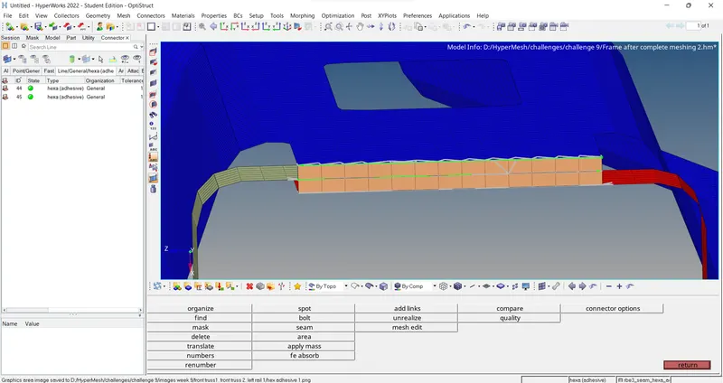
Figure: Front_truss_2, Front_truss_1 & Left_Rail_1 with hexa(adhesive) after mesh correction
5. Rear_truss_2 & Right_Rail_2:- Bolt Connector
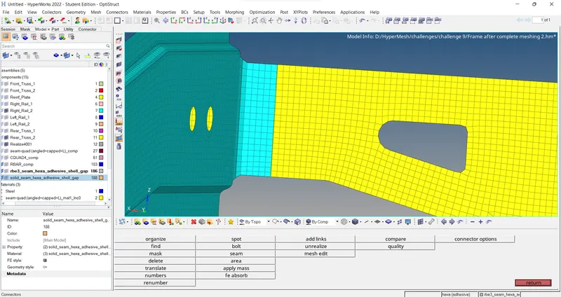
Figure: Rear_truss_2 & Right_Rail_2 before connector
To create a Bolt between the components, use the option
1D → connectors → bolt → choose type: bolt(CBAR), location: nodes, select components, create hole, if none → create
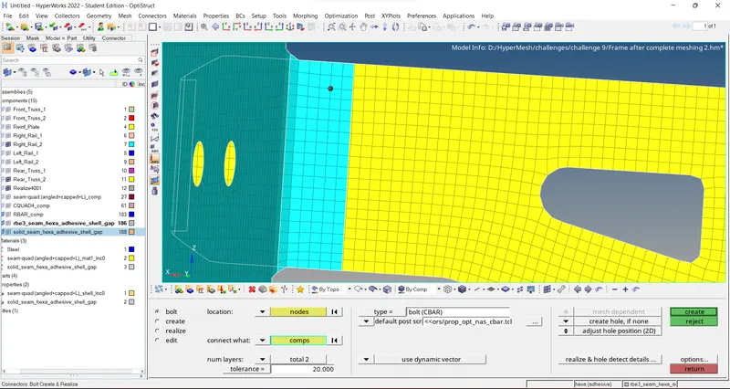
Figure: Rear_truss_2 & Right_Rail_2 connecting
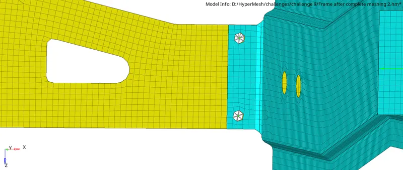
Figure: Rear_truss_2 & Right_Rail_2 connected and meshflow corrected
6. Rear_truss_2 & Left_Rail_2:- Bolt Connector
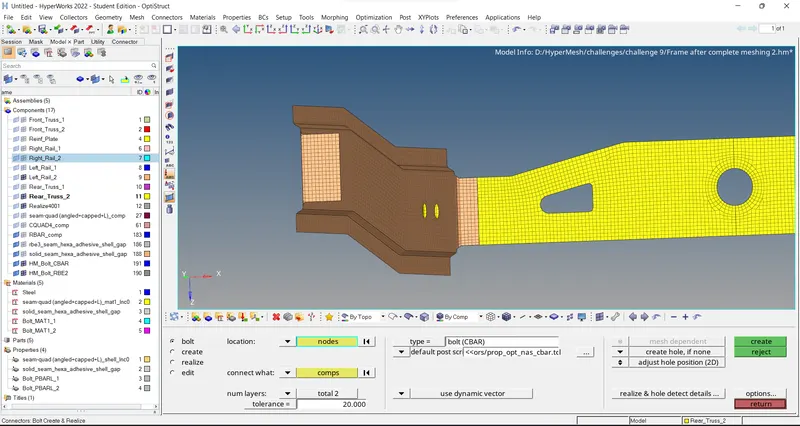
Figure: Rear_truss_2 & Left_Rail_2 without connector
To create a Bolt between the components, use the option
1D → connectors → bolt → choose type: bolt(CBAR), location: nodes, select components, create hole, if none → create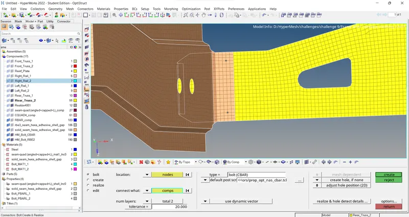
Figure: Rear_truss_2 & Leftt_Rail_2 connecting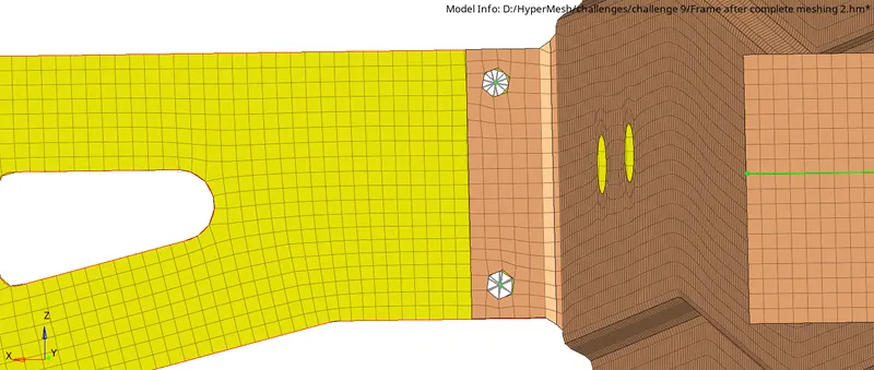
Figure: Rear_truss_2 & Left_Rail_2 connected and meshflow corrected
7. Right_Rail_1 & Right_Rail_2:- Spot-weld with Rigid Elements
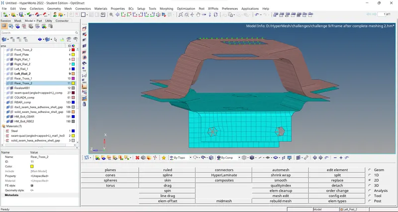
Figure: Right_Rail_1 & Right_Rail_2 without connector
To create Spot weld with Rigid Elements between the components, use the option
1D → connectors → spot → choose type: rigid, location: nodes, select components, num Layers: total 2, diameter 5 → create
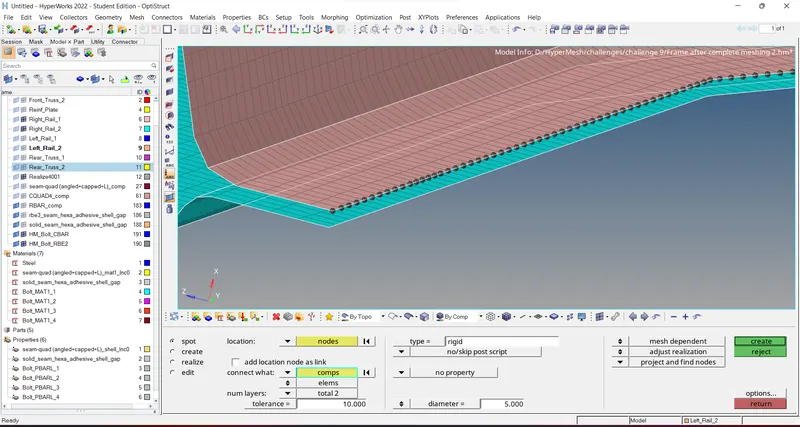
Figure: Right_Rail_1 & Right_Rail_2 connecting
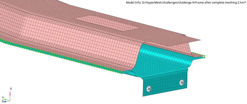
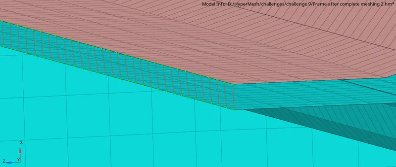
Figure: Right_Rail_1 & Right_Rail_2 with connector
8. Left_Rail_1 & Left_Rail_2:- Spot-weld with Spring Elements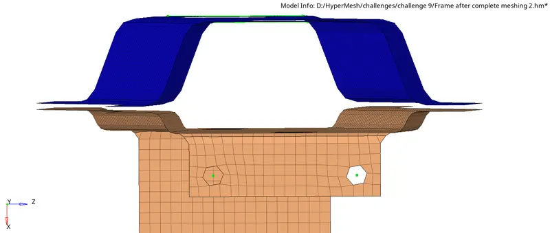
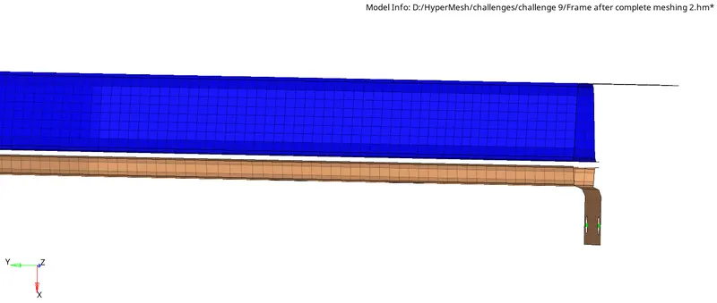
Figure: Left_Rail_1 & Left_Rail_2 without connector
To create Spot weld with Spring Elements between the components, use the option
1D → connectors → spot → choose type: spring, location: nodes, select components, num Layers: total 2, diameter 5 → create
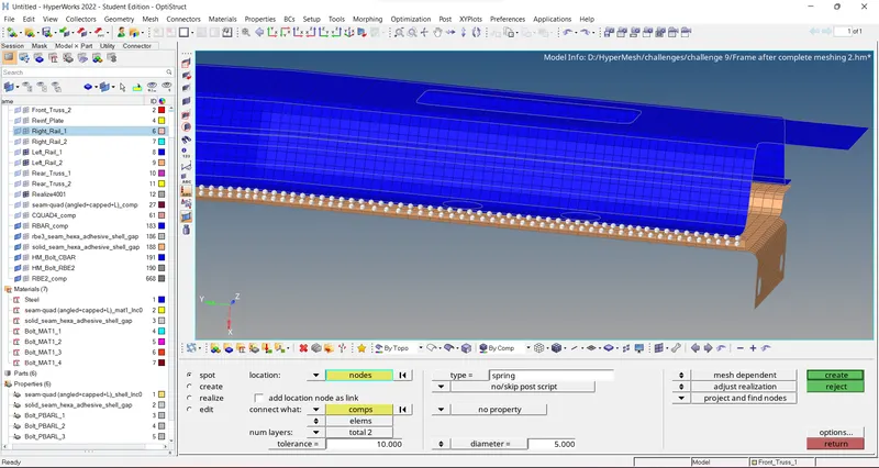
Figure: Left_Rail_1 & Left_Rail_2 connecting
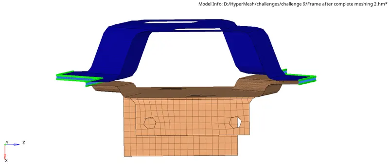
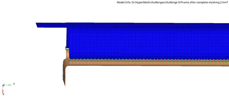
Figure: Left_Rail_1 & Left_Rail_2 connected
9.Right_Rail_2 & Front_truss_2:- Seam-Quad(angled+capped+L)
We connect them in the same way as we connected Right_Rail_2 & Front_truss_1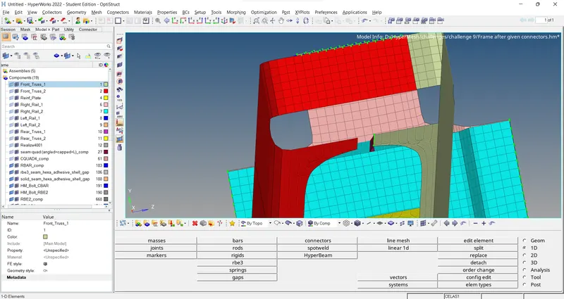
Figure: Right_Rail_2 & Front_truss_2 without connector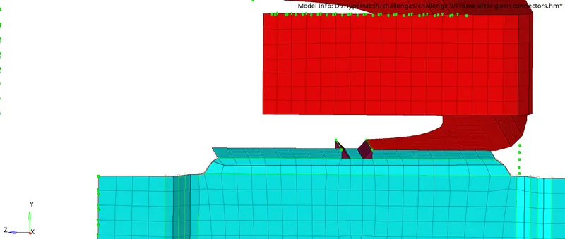
Figure: Right_Rail_2 & Front_truss_2 connected
10.Left_Rail_2 & Front_truss_2:- Quad elements
We connect them in the same way as we connected Leftt_Rail_2 & Front_truss_1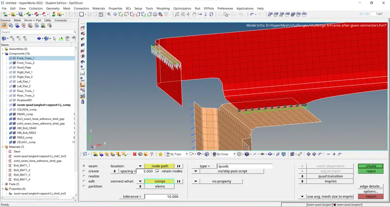
Figure: Left_Rail_2 & Front_truss_2 connecting with quad elements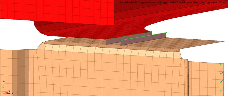
Figure: Left_Rail_2 & Front_truss_2 connected with quad elements
11.Rear_truss_1 and Rear_truss_2- Spot weld with Rigid Elements
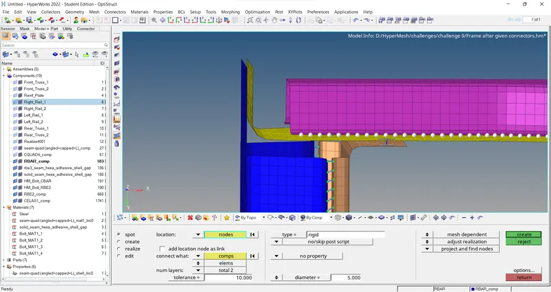
Figure: Rear_truss_1 and Rear_truss_2 connecting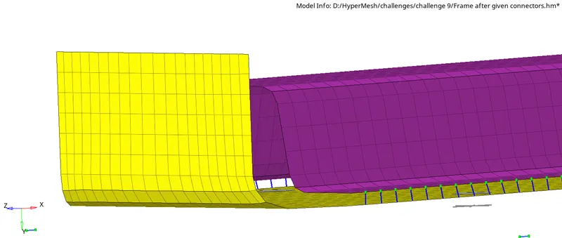
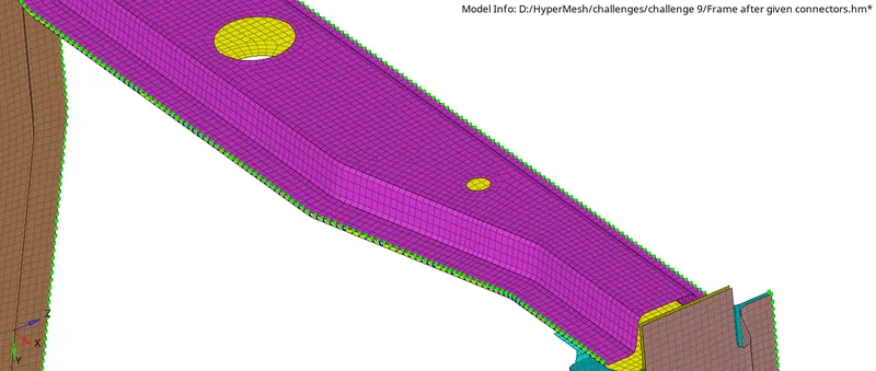
Figure: Rear_truss_1 and Rear_truss_2 connected
12. Rear_truss_2 and Left_rail_1- Bolt Connector
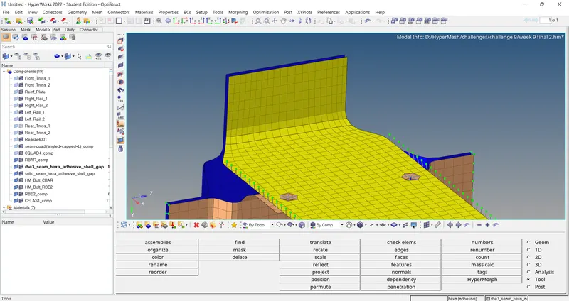
Figure: Rear_truss_2 and Left_rail_1 without connector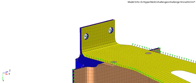
Figure: Rear_truss_2 and Left_rail_1 with Bolt Connector
13.Rear_truss_2 and Right_rail_1- Bolt Connector
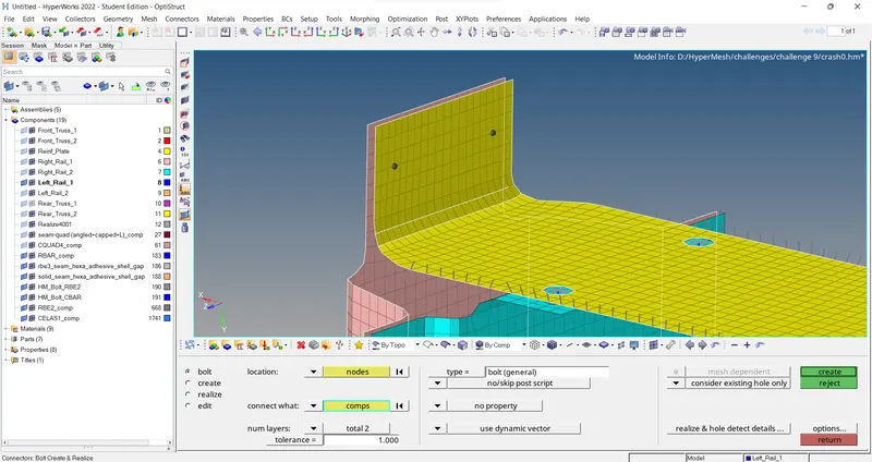
Figure: Rear_truss_2 and Right_rail_1 connecting
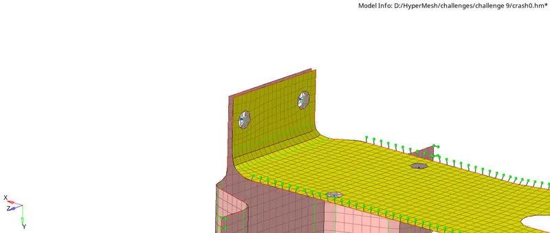
Figure: Rear_truss_2 and Right_rail_1 with Bolt Connector
14.Reinforcement plate, Front_truss_1,Front_truss_2- Quad Elements
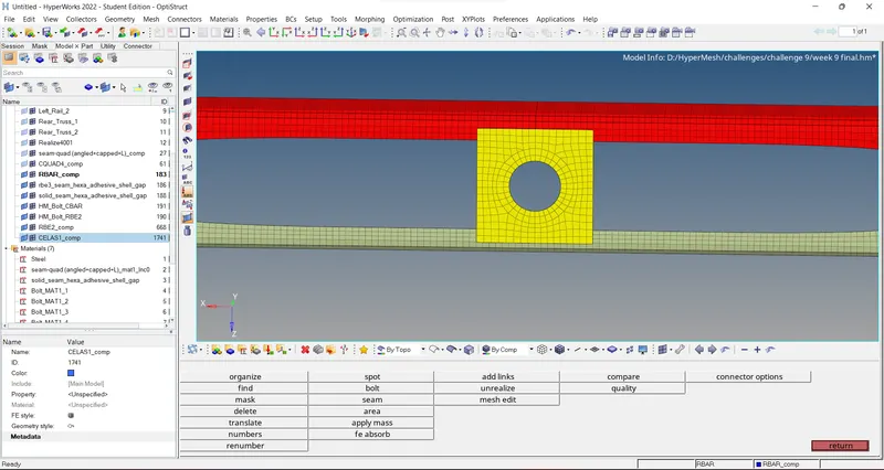
Figure:Reinforcement plate, Front_truss_1,Front_truss_2 without connector
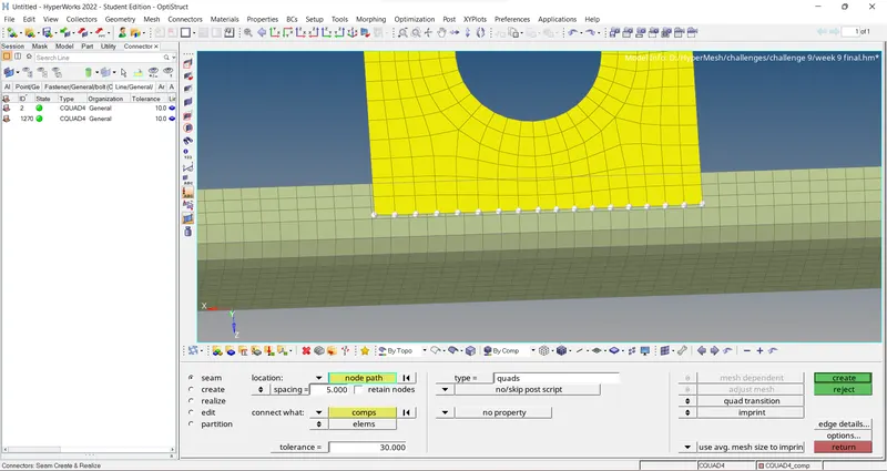
Figure:Reinforcement plate, Front_truss_1,Front_truss_2 connecting
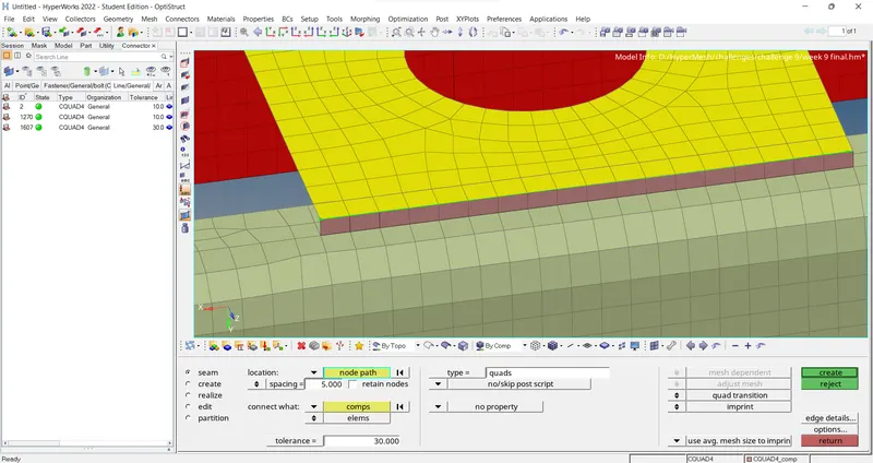
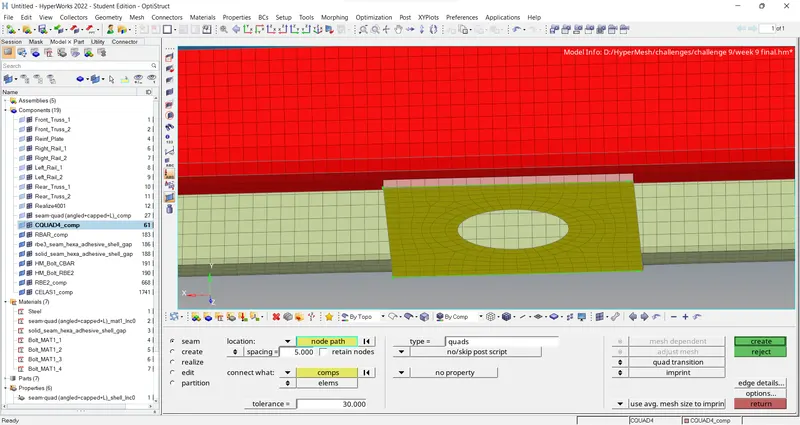
Figure:Reinforcement plate, Front_truss_1,Front_truss_2 connected
5.Results:
- Generated mesh on the given geometry as per the required quality parameters using HyperWorks.
- Connected the components of the given model using suitable connectors.
- The Final mesh with connectors is shown below:
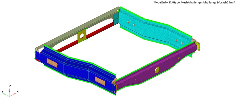
Figure: Final meshed model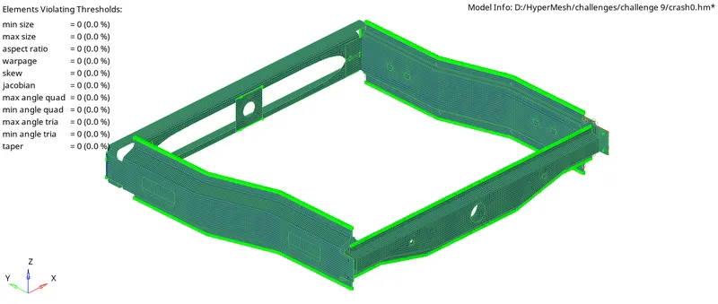
Figure:qualityindex of Final meshed model
6.Conclusions:
- This challenge helped me to understand about various 1D connectors available in HyperWorks and their uses.
- This challenge also helped me to have in hand experience with the various connectors in HyperWorks and taught me the imporatance of connectors in a model.