Week 8-3D Tetra Meshing Challenge
3D Tetra Meshing Challenge
1.Aim: To carry out Tetra meshing on the given models in HyperWorks.
2.Objectives:
- To create a Tetramesh for the given Housing component with the following quality criteria using 2D to 3D conversion method.
Elements sizes: Min- 2 Units, Target- 5 Units, Max- 7 Units
Tet collapse: 0.15 - To create a 3D Tetramesh on the given model with the following quality criteria using Quick Tetra Mesh/ Volume Tetra Mesh.
Target Element size: 3 Units.
Tet Collapse: 0.15 - To create a 3D Tetramesh on the given assembly model(Turbo charger) with the following quality criteria using Quick Tetra Mesh/ Volume Tetra Mesh.
Target Element size: 4 Units.
Tet Collapse: 0.15
3.Theory:
- 3D elements are usually used to mesh volumes. They are derived from 2D elements that are used when the problem is unable to be simplified. 3D solid elements only account for translational displacements.
- These elements are suitable for three-dimensional analysis. They are mainly used to mesh solid parts and sheets of thickness more than 5mm, transmission castings. engine blocks etc.
- Tetra element, 4 noded with 4 triangle faces are formulated in three-dimensional space with three degrees of freedom per node. These are the translational degrees of freedom in the X, Y and Z directions, respectively. In the figure Tetra element is shown for 4 nodes and 10 nodes.
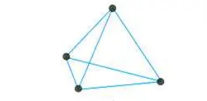
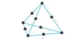
-
There are two methods of tetra meshing:
1. Automatic mesh: This approach is limited to simple geometries and pre-requisite is error free CAD model. User selects the volume and software automatically, carries out meshing as per specified element length, quality criteria etc.
Advantages: Very quick, no meshing efforts
Disadvantages: Results in very high number of nodes and elements. There is no control on mesh flow lines and specific mesh pattern requirement (like bolted, welded joints or contact surface simulation).
2. 2D (Tria) to 3D (Tetra): Most commonly used method. Quad or tria meshing is carried out on all the outer surface of the geometry, quads split into trias and then converted to tetras. - Tetra Collapse: Ideal Value = 1.0 (Acceptable > 0.1)
Tetra collapse = h*1.24/A (Defined as distance of node from opposite face divided by area of the face multiplied by 1.24)

4.Procedure: Since we are given three different models, each model is meshed and saved separately. For this challenge we will be using the userprofile RADIOSS since we are carrying out 3D meshing.
Step 1: Importing the geometry
- To import the geometry, go to file → Import → Import geometry → Import.
Model-1: File name: housing.stp
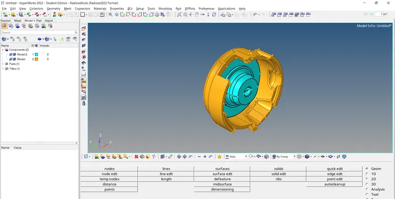
The housing model consists of two components which are highlighted in different colours as shown in the image.
Model -2: File name: Week 8 Model2.iges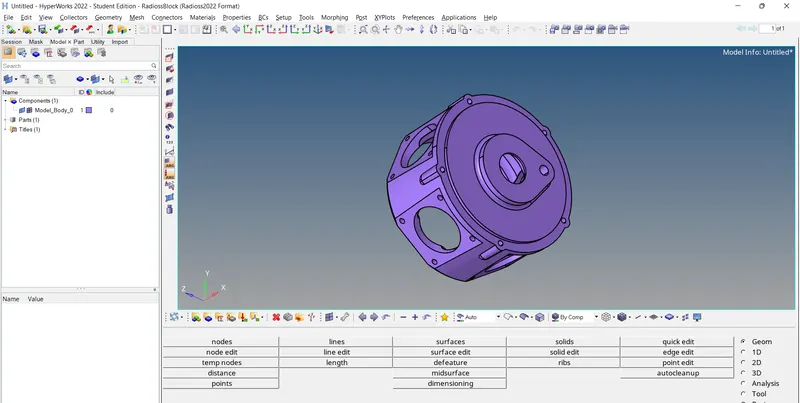
Model -3: File name: Turbo Charger_Week_8.hm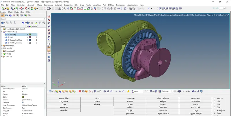
- After importing the geometry, the geometry is checked for any missing surfaces or any other errors and then correct it.
Step 2: Setting the Criteria and Topology cleanup
- We input the given criteria into the HyperWorks software for the respective model using the options
Preferences → criteria file settings and Preferences → parameter file settings.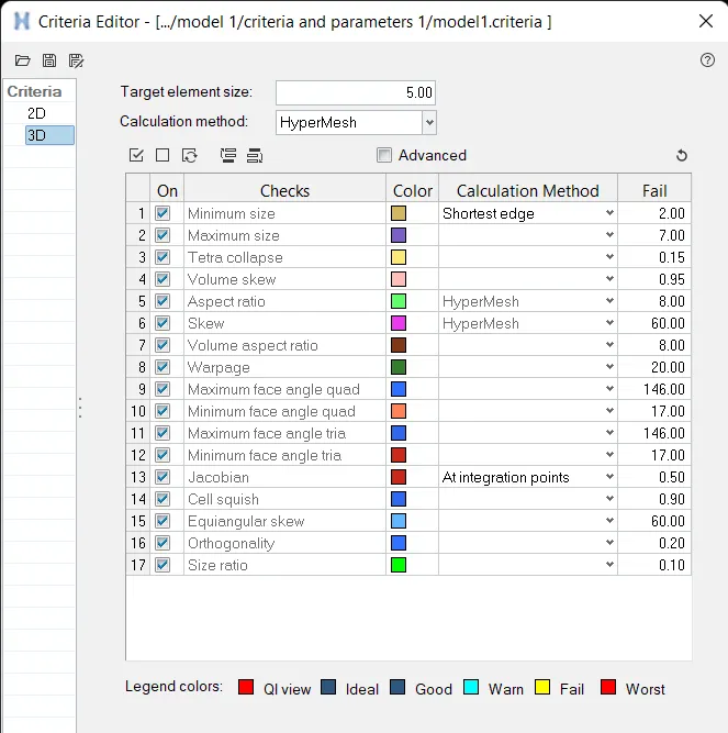
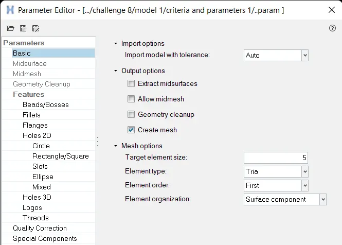
We also save them to be used later, if required. - Then we remove the solids using the option delete → Solid → Select solid → delete entity.
- Prior to meshing we do Geometry or Topology Clean-up in which we check for any free lines, unfilled surfaces and other errors.
- Toggle the unwanted lines(other than Feature lines) for better meshing.
- Remove the surface fillets having maximum radius less than the minimum mesh length using the option defeature → surf fillets → select the surfaces → min radius=0.1, max radius= min mesh length → find → delete.
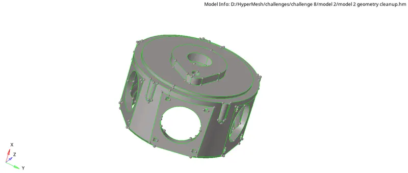
Figure: Model 2 after Topology clean-up
Step 3: Meshing
Model 1(Housing component)
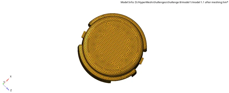
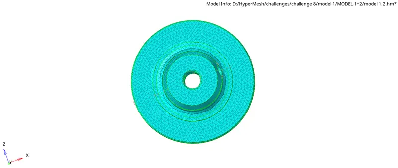
- Here we are asked to generate 3D mesh on the given component using 2D to 3D conversion method. Hence we need to make 2D(trias) shell elements first, correct them for any errors as per the given quality criteria, convert them to 3d tetra elements and check for 3D quality criteria.
- Generate the 2D mesh using the option 2D → automesh → select surface, element size=5, mesh type=trias → mesh.
- Check quality criteria for the generated 2D tria elements using 2D → qualityindex. Correct the failing elements as per criteria by using smooth, element optimize, rebuild mesh etc. Before using rebuild, the parameter should be corrected with mesh type as trias only.
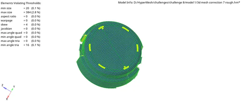
Figure: qualityindex before correcting the errors
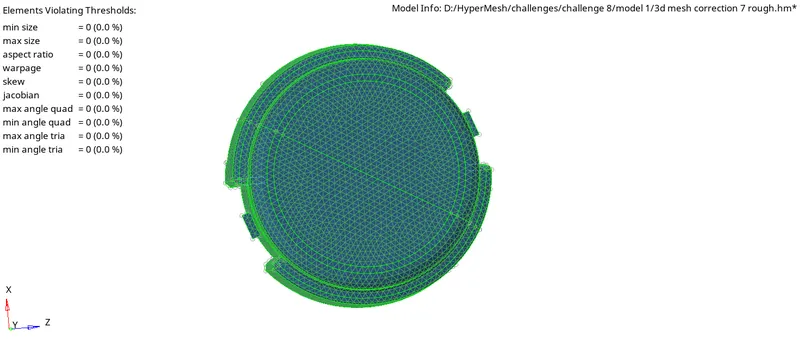
Figure: qualityindex after correcting the errors - The next step is to generate 3D tetra mesh from already created 2D tria elements. For this we use the option
3D → Tetramesh → Instead of comps. select elements and select displayed → mesh.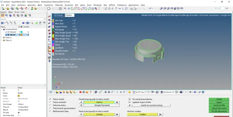
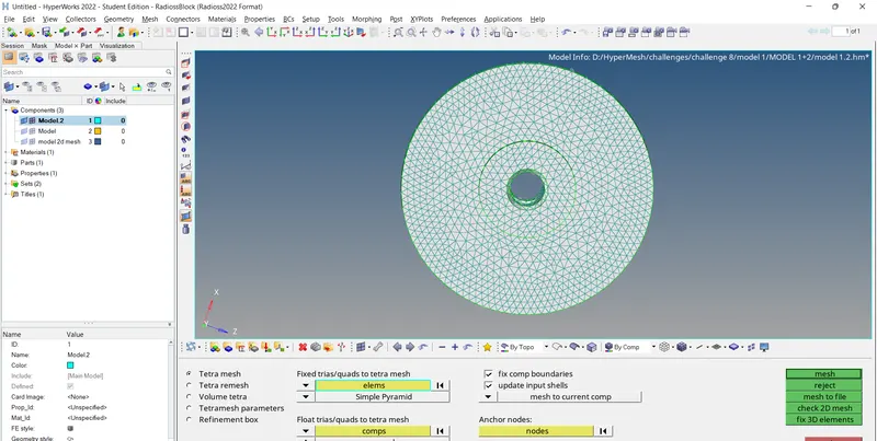
Prior to this we input the Tetramesh parameters using 3D → Tetramesh → TetraMesh parameter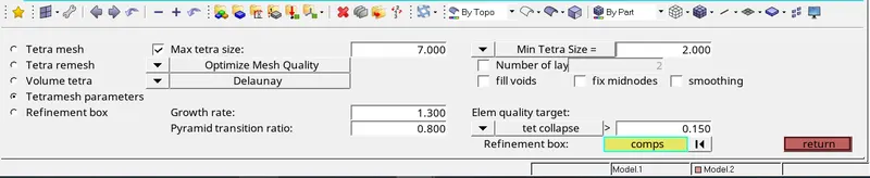
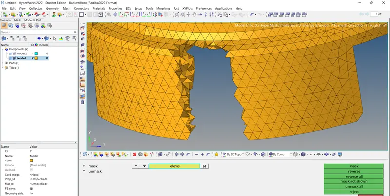
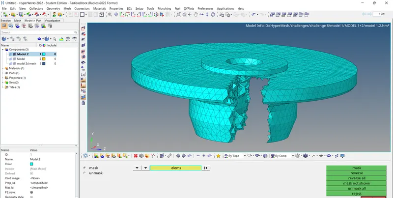
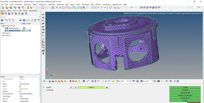
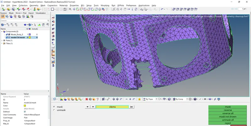
- Now by using the mask tool check whether the Tetra elements have been successfully created in the model.
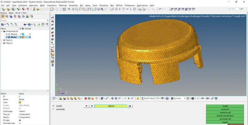
- Finaly we delete the 2D shell elements using the option
Delete(F2) → elems → By config. → select config. as tria3 → select entities → return → delete entity.
Model 2:
- The second model is meshed with Quick Tetra Mesh/ Volume Tetra Mesh. These methods are used when we are not that much concerned about the quality criteria.
- Firstly we input the criteria and parameter values as discussed earlier.
- Then we check the Tetramesh parameters using 3D → Tetramesh → TetraMesh parameter.
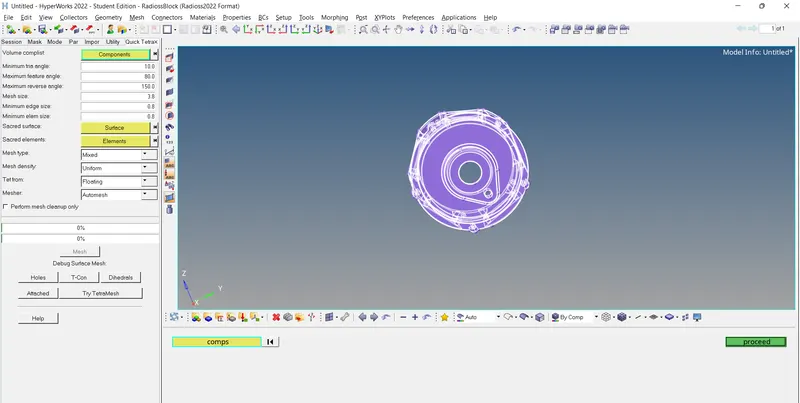
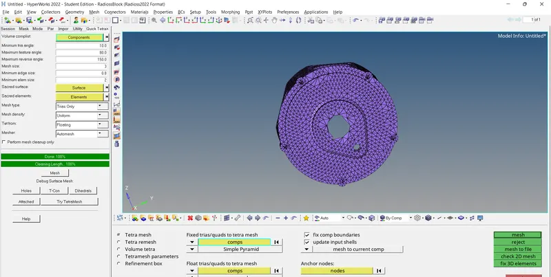
- Method 1: Quick Tetra Mesh
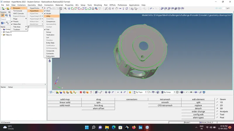
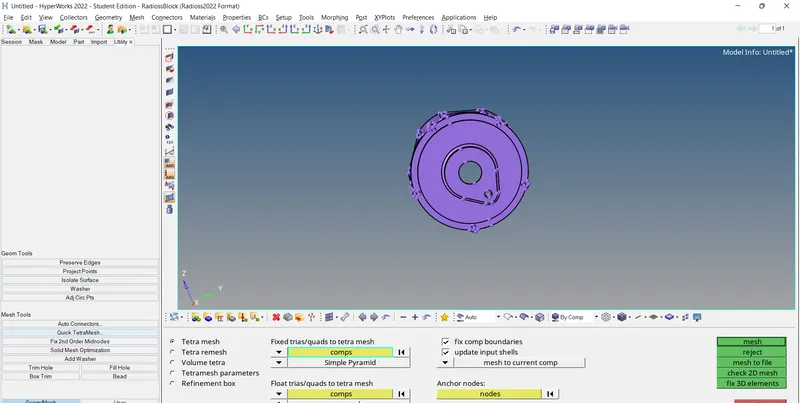
View → Browser → HyperMesh → Utility → Geom/mesh → Quick tetramesh → select comp. → we can fix mini. tria angle, max. feature angle, max reverse angle, mesh size (3), minimum edge size, mini. element size → mesh type (trias only) → mesh
- Method 2: Volume Tetra Mesh
I have used this method to mesh my model. After keeping the 3D parameters as mentioned in previous case, we generate the Volume Tetra Mesh using the option
3D → Tetramesh → Volume tetra → select solids / surface → set element size → mesh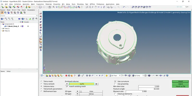
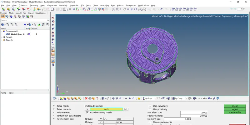
- Soon after the Tetra mesh is created, we check whether the Tetra mesh has been created successfully by using the mask tool.
Model 3(Turbo Charger):
- Here also I have used Volume Tetra Mesh, although it can also be meshed using Quick Tetra Mesh option.
- There are four components in the given turbocharger model namely Casing, Hub, Supporting plate and Holder housing. Each part is meshed separately.
- First set the criteria as well as parameter. 3D → Tetramesh → TetraMesh parameter
- Then we mesh each of the components using the option
3D → Tetramesh → Volume tetra → select solids / surface → set element size(4) → mesh. - As in the previous case, after meshing we mask a portion of mesh to check whether the entire volume has been captured by the mesh properly.
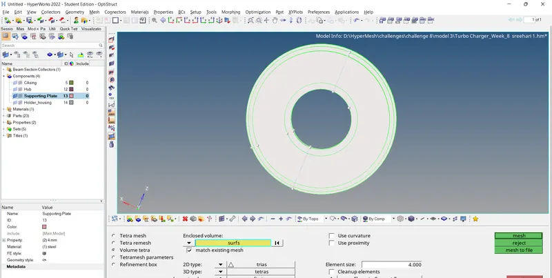
Figure: Meshing the Supporting Plate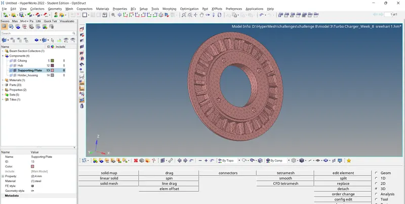
Figure: Tetra meshed Supporting Plate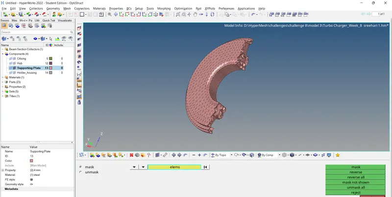
Figure: Checking for Tetra Mesh
Step 4: Quality checking
- Each model is checked for mesh quality as per given criteria using the check elems option in Tools.
Tools → Check elements → 3D. - Our primary focus is to check for Tet collapse followed by minimum and maximum length and finally connectivity,duplicates.
- If any error found, correct it manually by using translate, distance tools etc... Also we can use tetra remesh tool.
To see the failing element, click on
Tools → check elems → 3D → click on quality you want to check (say tet collapse)→ save failed → return.
Then, Tools → mask → element → retrieve → mask → reverse. This step will show the elements which are failing.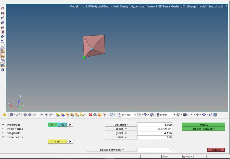
Figure: Editing minimum/maximum length using distance tool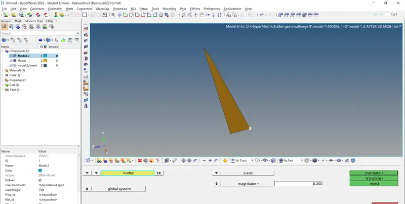
Figure: Correcting Tet collapse using translate tool
5.Outputs:
5.1 Model 1(Housing component)
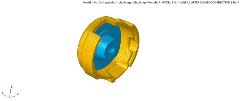
Figure: Model 1 3D Tetra Mesh
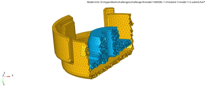
Figure: Model 1 Checking 3D Tetra Mesh
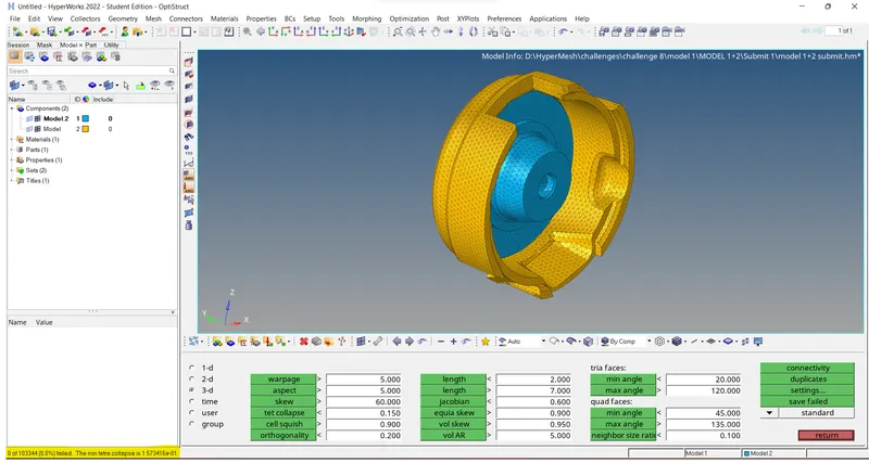
Figure: Model 1 Check for Tetra collapse
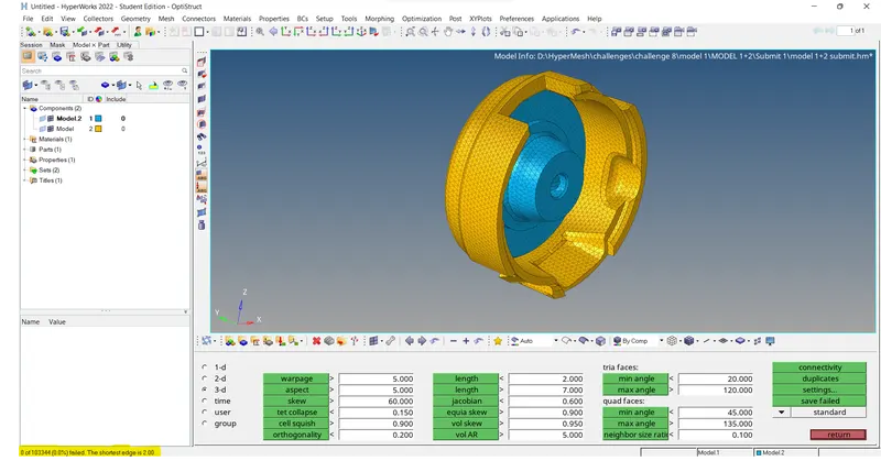
Figure: Model 1 Check for minimum length
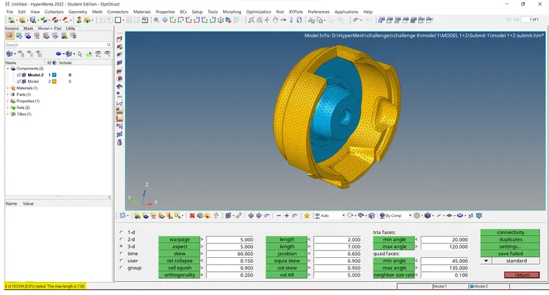
Figure: Model 1 Check for maximum length
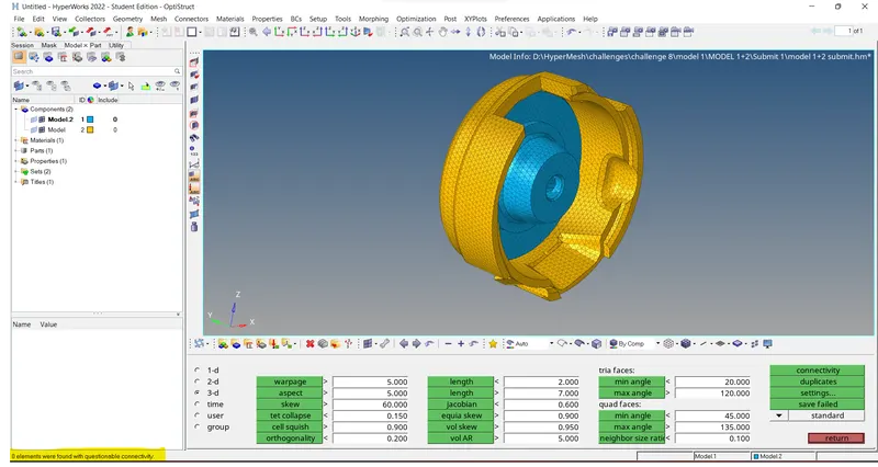
Figure: Model 1 Check for connectivity
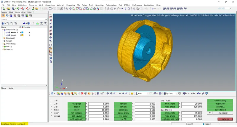
Figure: Model 1 Check for duplicates
5.2 Model 2
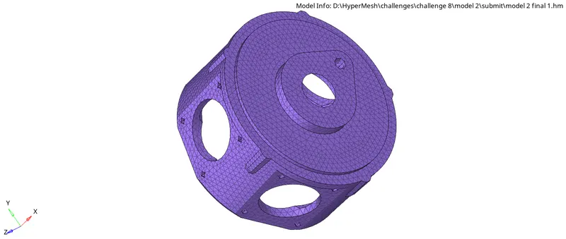
Figure: Model 2 3D Tetra Mesh
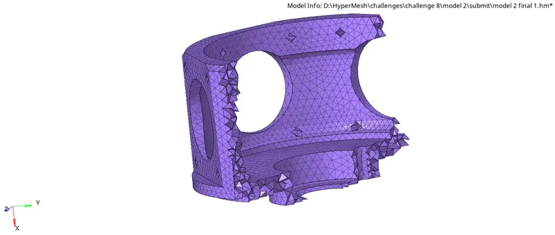
Figure: Model 2 Checking 3D Tetra Mesh
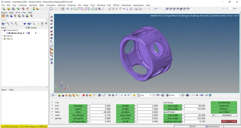
Figure: Model 2 Check for Tetra collapse
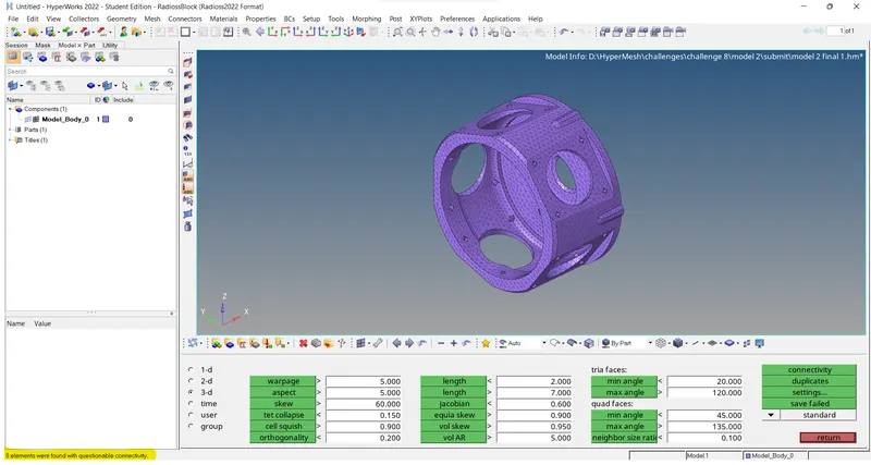
Figure: Model 2 Check for connectivity
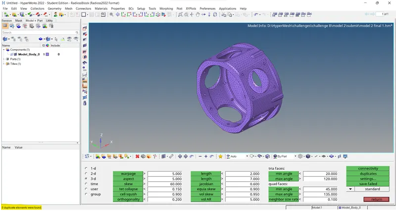
Figure: Model 2 Check for duplicates
5.3 Model 3(Turbo Charger)
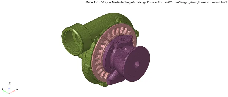
Figure: Model 3 3D Tetra Mesh
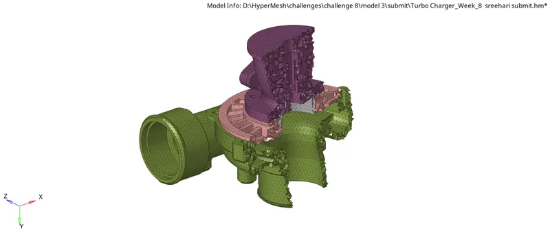
Figure: Model 3 Checking 3D Tetra Mesh
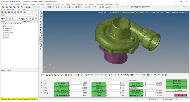
Figure: Model 3 Check for Tetra collapse
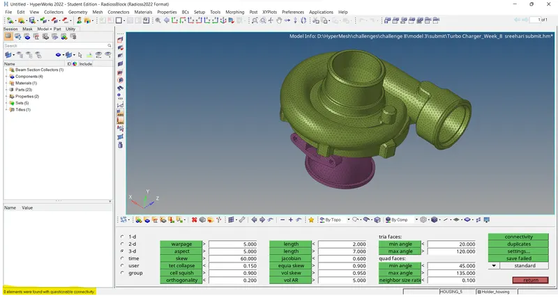
Figure: Model 3 Check for connectivity
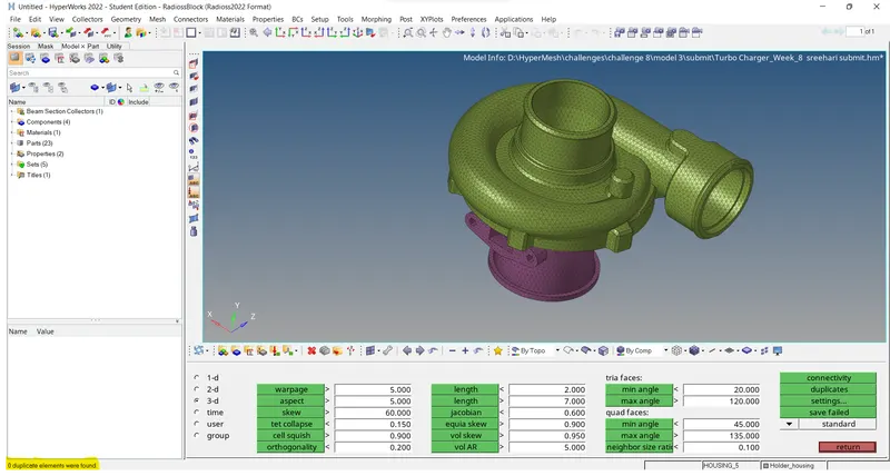
Figure: Model 3 Check for duplicates
6.Results:
- Created a Tetramesh for the given Housing component satisfying the quality criteria using 2D to 3D conversion method.
- Created a 3D Tetramesh on the given model with the required quality criteria using Volume Tetra Mesh.
- Created a 3D Tetramesh on the given assembly model(Turbo charger) with the mentioned quality criteria using Volume Tetra Mesh.
7.Conclusions:
This challenge helps us to learn about 3D Tetra Meshing and the various methods used for 3D meshing namely, 2D to 3D conversion method, Quick Tetra Mesh and Volume Tetra Mesh. This challenge introduces us to various tools in 3D tetramesh tab as well as the tools used to correct errors in Tetramesh.