Week 6-Meshing of Hood Challenge
2D MESHING OF HOOD
1.Aim: To mesh the given component[Hood] as per the mentioned quality criteria and assign property and thickness to the component using HyperMesh.
2.Objective:
- To extract the midsurface of each of the four subcomponents[Inner extract,Outer extract,Latch reinforcement extract and Hinge reinforcement extract] of the hood separately.
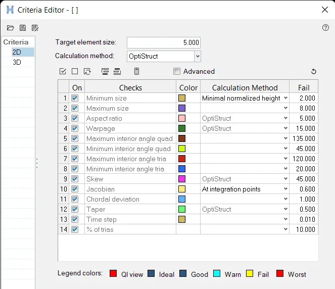
- To mesh the midsurfaces as per the given quality criteria:
Target Element Length = 5 Units
S.N Quality Criteria Value 1 Aspect Ratio 5 2 Skewness 45 3 Warping 15 4 Taper 0.5 5 Min. Length 2 Units 6 Max. Length 8 Units 7 Min angle Quad 45 8 Max angle Quad 135 9 Min angle Tria 20 10 Max angle Tria 120 10 Tria % 10 - To check and validate the quality of mesh using the "qualityindex" and various model check options available in HyperMesh.
3.Theory:
Engine cover or Engine hood is the most eye-catching body component and important opening piece to the body, which directly affects the overall performance and comfort. Front cover assembly not only plays an important role in air guiding, but also protects the engine and surrounding pipeline accessories, meanwhile it can sufficiently avoid impact, corrosion, rainwater and electric interference.
The following are the design consideration involved in the Design of Engine Hood.
- Pedestrian Safety:
Pedestrian safety always a factor involved in the design of the hood. This is achieved by proper selection of material that can readily deform avoiding risk during impact, Providing embosses to inner panels, etc. This is one of the major factors for a vehicle to have better safety ratings.
- Vehicle Quality:
This involves how best the hood can be designed to have better quality in terms of Torsional stiffness, dent resistance(Hailstone and stone chippings), Corrosion resistance better weight distribution, and noise attenuation.
- Occupant Safety:
The design consideration must include the impact caused due to Frontal Crash Collapse. Such Scenario is expected that Hood maintains its Integrity with hinges and also retain any of loosed components from Engine Compartments.
- Styling:
Better Surface quality (A-class Surface Finishing), Tight radii on hemmed panel edges & low strain between curved regions of the inner and outer panel.
- Manufacturability:
The design should be always considered for manufacturability e.g. Embossing on the inner Panel should have sufficient draft angles provided for the Punching tool to flowin and flow-out. Any Design should be studied for Manufacturability in order to produce it.
Material selection for automotive closures is influenced by different factors such as cost, weight and structural performance.The commonly used materials are Steel and Aluminium.
4.Procedure:
Step 1: Importing the geometry and Topology cleanup
- Firstly, we import the Geometry given to us into the HyperWorks software.We are given a CAD model of a car hood divided into four subcomponents namely Latch reinforcement,Hinge reinforcement, Inner and Outer extracts. For importing the file we use the option
File → Import → Import geometry → Choose the file in '.stp' format → Import.
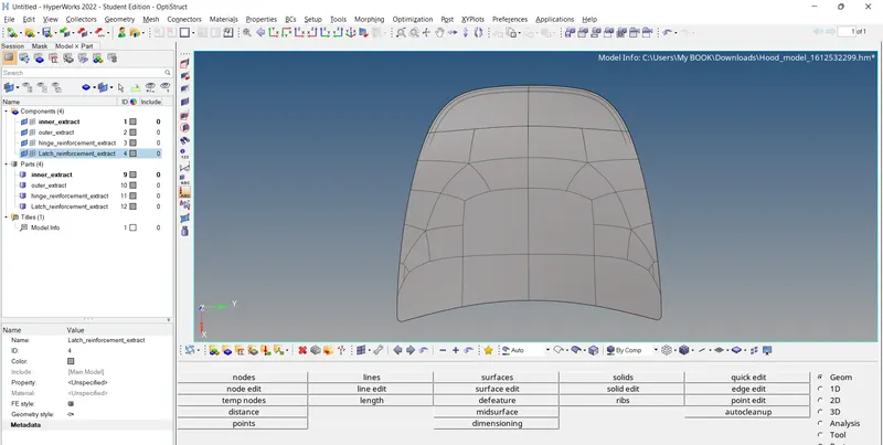
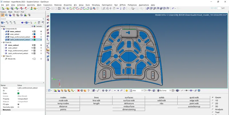
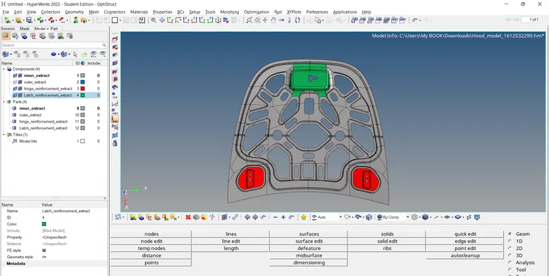
The CAD model image is shown below with the subcomponents highlighted in different colours.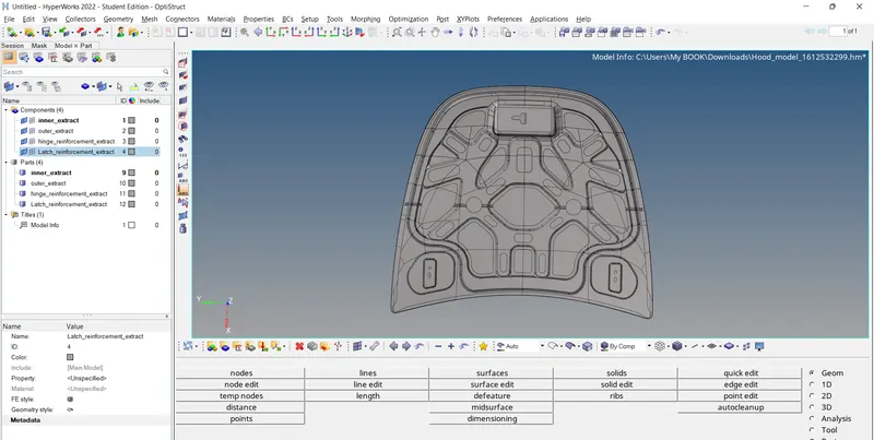
- After importing the geometry we carry out Topology cleanup on each of the four subcomponents in which the geometry is checked for any missing surfaces or triple cons.Once such errors are rectified the geometry is ready for mid-surface extraction.
Step 2: Mid-surface generation
- Hood or Bonnet is considered to be a sheet metal component(thickness<6mm).Hence we carry out meshing on midsurface of the component.
- Before extracting the midsurface, we delete all the solids of that particular part of the component. This is done using the option
Delete → Solid → Select solid → delete entity. Then using "By Topo" geometry color mode check the model for free lines and errors.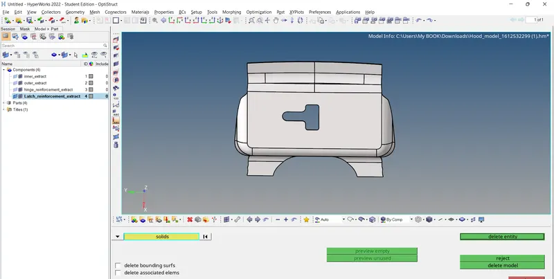
- After checking the model, the midsurface of the respective part is extracted and named appropriately.Midsurface is extracted using the option Geom. → auto midsurface → select surface → extract.
Selected extraction option: skin offset.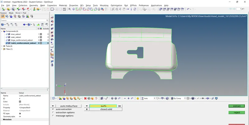
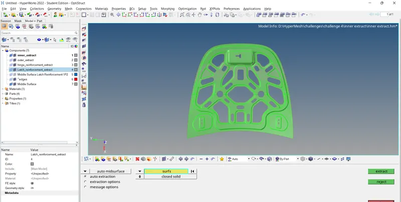
- After extracting the midsurface itself we can create the material and properties(defining the thickness value) and assign them to the respective part. Here, thickness of each component is measured by using the distance option in Geom.
The property created for Inner extract is shown below.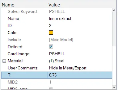
Then we assign this property to the part by clicking on the middle surface of Inner extract in components window and adding the property and material to it.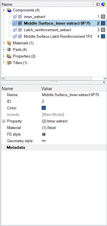
- The midsurface is also checked for any freelines and errors. Then the criteria file is saved using the option Preferences → criteria file settings.
Step 3: Auto cleanup
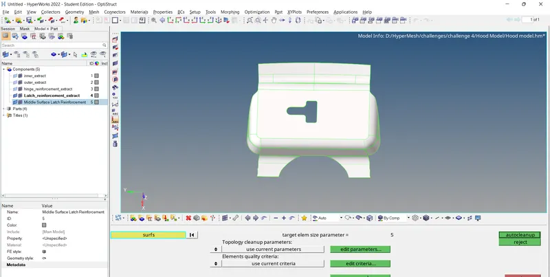
- Prior to meshing we do "auto cleanup"
- This option comes very handy to toggle the unwanted lines,pinholes etc.which would ultimately help to achieve a better quality mesh.
Step 4: Surface trimming
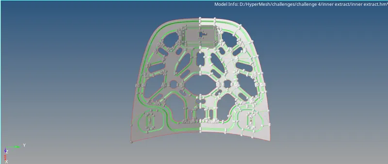
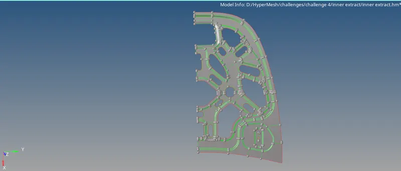
- For components which are symmetric, for example, inner and outer extracts in this particular case, it is better to trim the midsurface at the plane of symmerty and carry out meshing only on half portion of the component.Later the mesh on the other half can be generated by duplicating and reflecting this mesh on to the other half. This effectively reduces the mesh time and human effort.
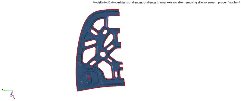
Figure:Inner Extract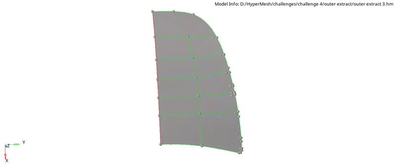
Figure:Outer Extract - In case of inner extract, while trimming off the surfaces, the region where the latch reinforcement is to fit in should be excluded because it is not symmetric. That portion should be meshed separately.
Step 5: Meshing
- The next step is to mesh the component. In case of Latch reinforcement, we mesh the entire component, while in case of symmetric components like inner and outer extracts we mesh only the half portion of the component and reflect a duplicated mesh to the remaining half. Hinge is a special case where the same component is repeated twice. Hence,we mesh only 1 component and reflect the mesh onto the next one.
- We can either batch mesh or mesh the entire component at once. For larger components it is advisable to do batch mesh for easier and better results.For this divide the component into rectangular components by using construction lines. This helps to avoid trias to a great extent.
- Here we are using mixed mesh(quads and trias) because we are preparing the model for crash & safety simulations. The quad-only mesh is preferred for durability and structural simulations.
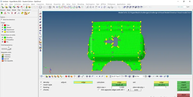
Figure: Meshing the Latch reinforcement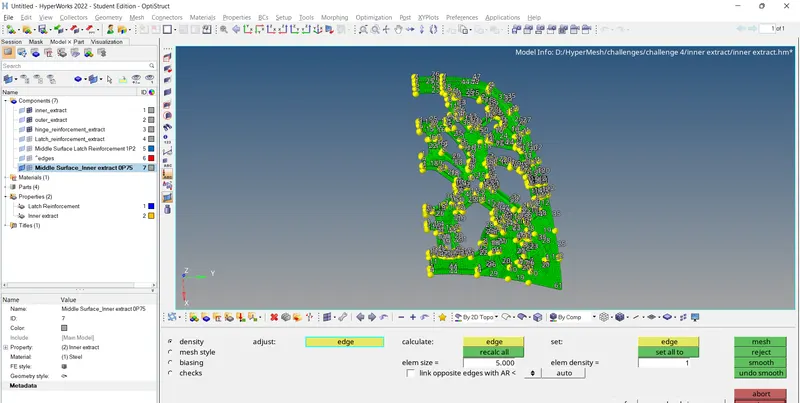
Figure: Meshing the Inner extract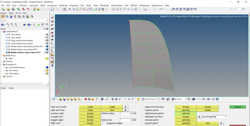
Figure: Construction lines modified on Outer extract for better quality batch meshing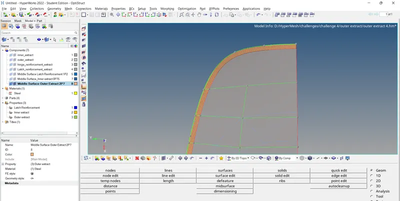
Figure: Batch meshing of Outer extract hemming region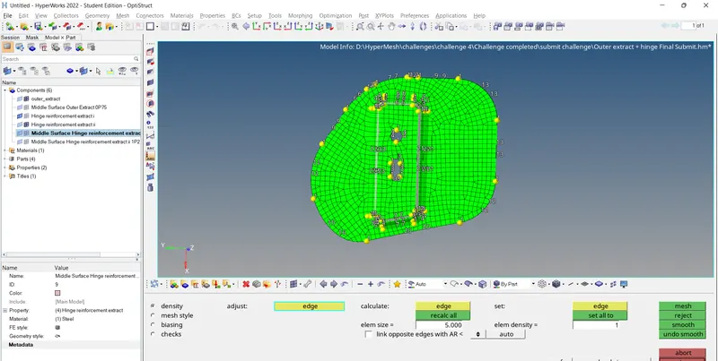
Figure: Meshing Hinge reinforcement - The initially obtained mesh may not be of high quality. We edit it by remeshing as well as by making use of rebuild mesh option.
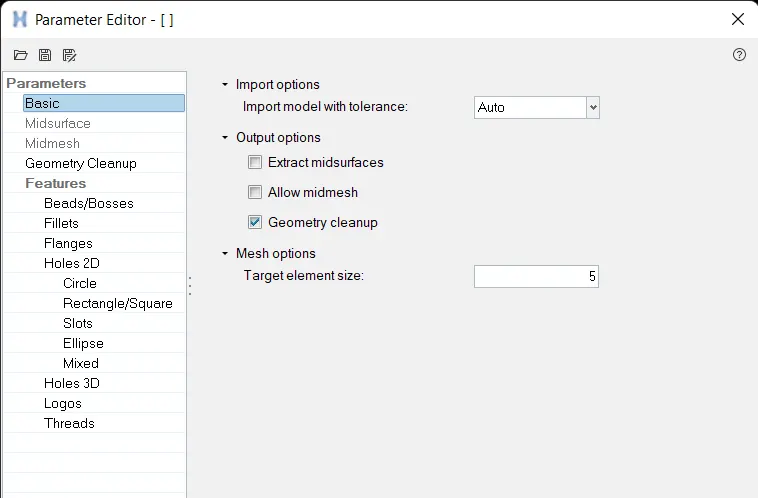
- We should check the criteria and parameter file settings from preferences drop down menu at the top of the HyperWorks window and ensure that required qulaity criteria is used as inputs.
Step 6: Quality checking
- This is the most important step in the entire process.Once after completing the mesh we need to check and ensure that the mesh so generated is as per the given quality criteria.
- For this we use the option 2D → qualityindex as well as Tool → check elems. There might be deviations in some or all of the quality criteria which we need to correct by using the various options available in the cleanup tool options available in the qualityindex.

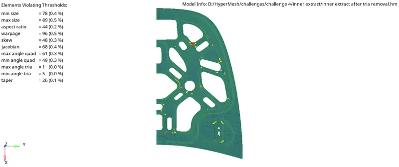
Figure: Deviations in qulatyindex for Inner extract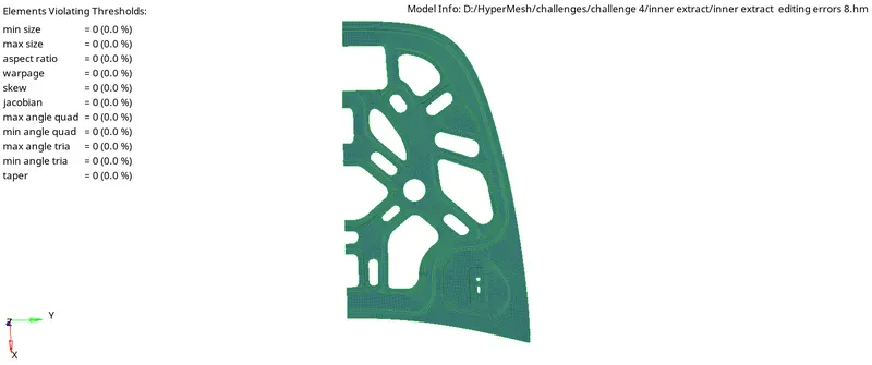
Figure: Inner extract after correcting all the deviations
Step 7: Completing the mesh using reflect tool
- Except for the Latch reinforcement, for the rest of the three components we need to reflect the mesh on to its other half. This is done by using the option Tool → reflect → select surfs/mesh to reflect and duplicate it → select base point and reflecting directon → reflect.
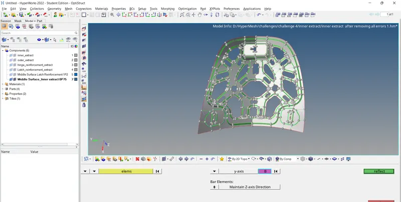
Figure: Reflecting the mesh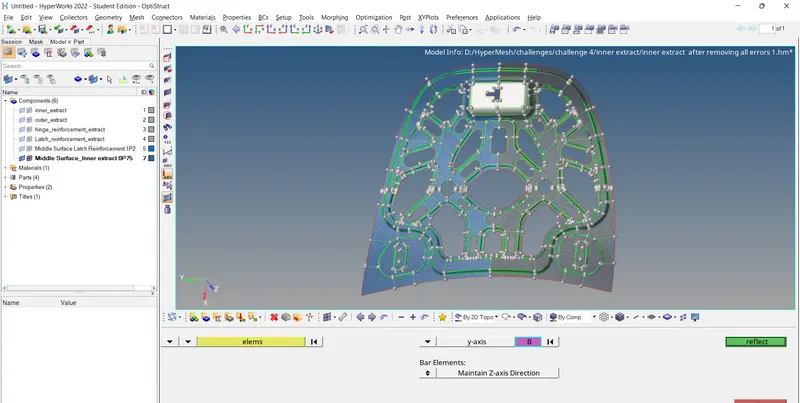
Figure:Reflected Mesh
Step 8: Model check
- Edges check: Find edges of the model for perfection.
Tools → edges → select element dispalyed → find edges
If no error noticed, delete edges . Else, Select the elements where there are Free Edges within the geometry → preview equiv → equivalence → return. Click on edges again and confirm that the edges have been removed.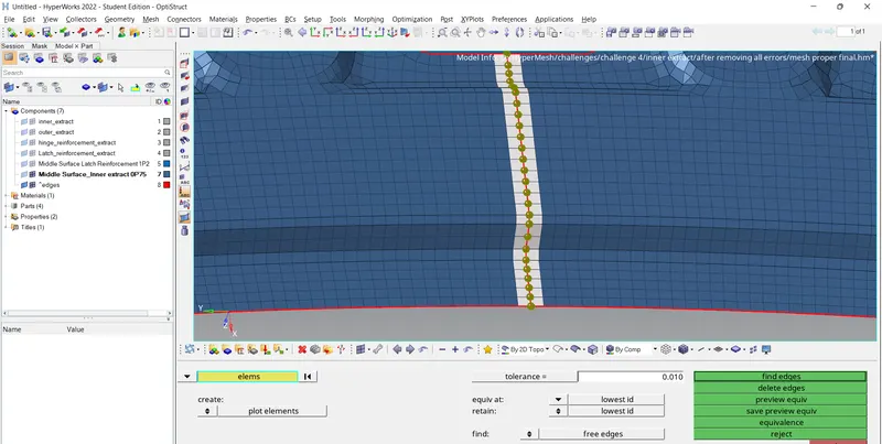
Figure: Removing the Free edges by equivalence option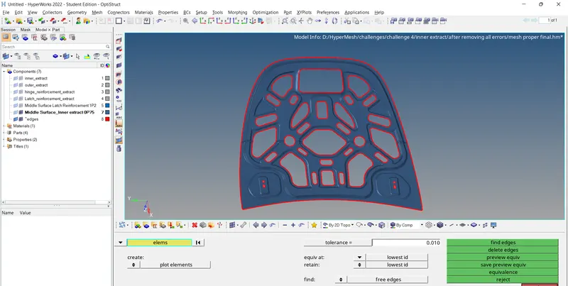
Figure: Final image after removing Free edges - Element to surface edge check: To check whether the elements have captured the surface geometry.From top drop down menu choose
mesh → check → elements → comparison → click on element tab shown in source entity → Select element displayed → Proceed → click surface tab in the target entity → select surface displayed → Proceed → Tolerance = 0.2 → Run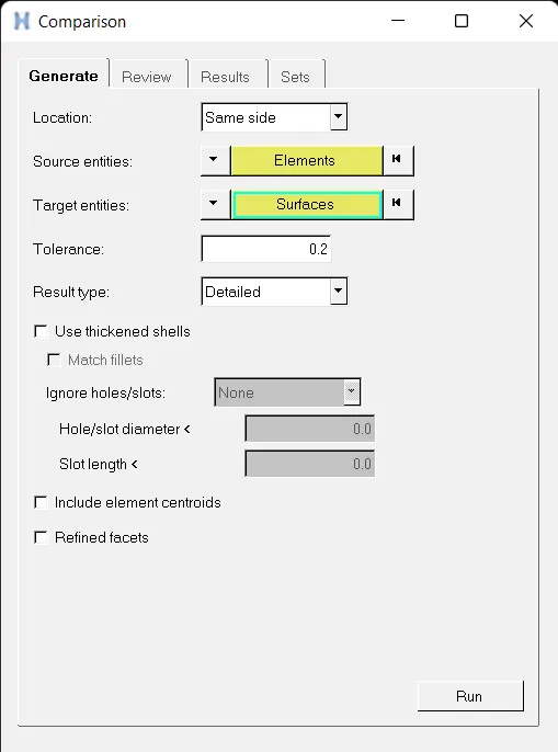
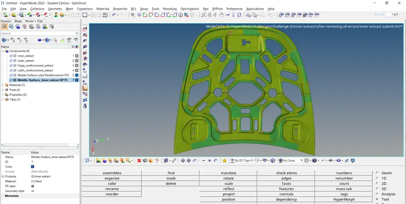
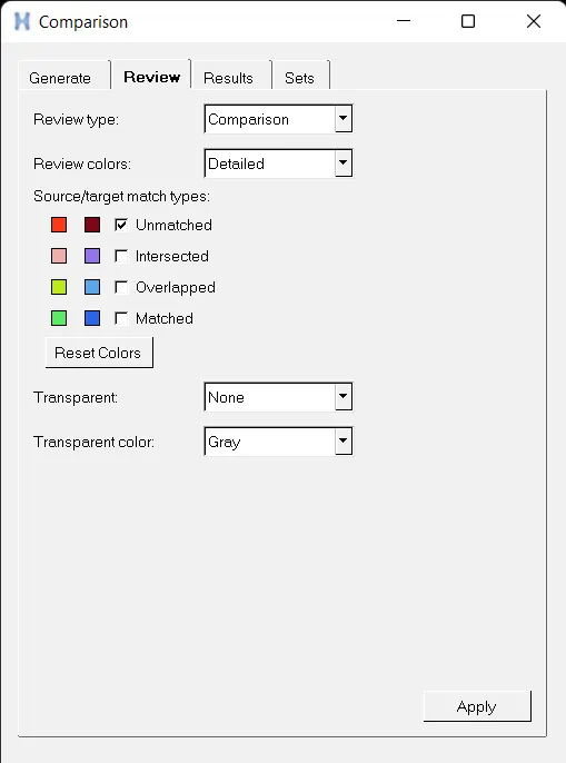
Here yellow and pink colors in mesh are okay but red colours need to be eliminated. In case of errors, we use Tool → project to rectify it. - Check for Normals: Tools → Normals → display 2D elems → choose colordisplay or vector display.
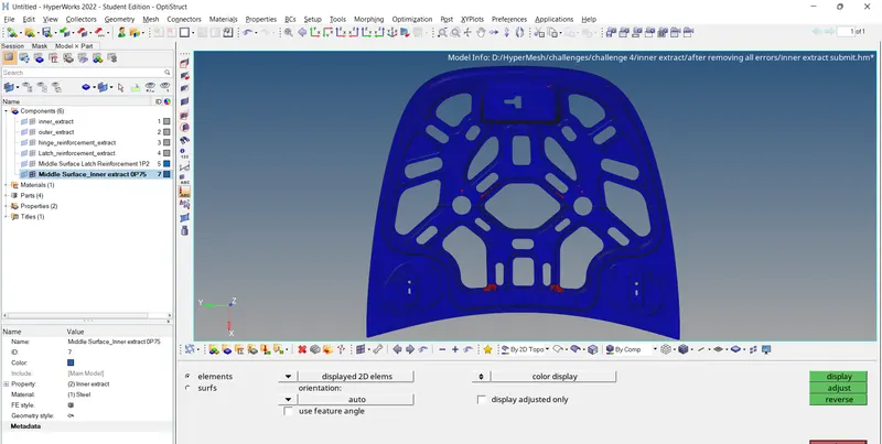
The defected element's normals are reversed using the same tool by selecting the elements and clicking reverse.
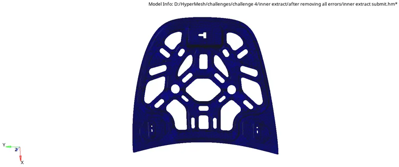
Figure:Final image of Inner extract after Normal correction - Penetration & intersection check: Penetration is defined as the overlap of the material thickness of shell elements, while intersection is defined as elements that actually pass completely through one another.
Tools → penetration → select element displayed → check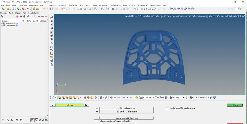
Figure: Penetration check for Inner extract
Once, all these quality checks are fulfilled,our component is ready for analysis.
5.Outputs:
5.1 Latch Reinforcement extract:
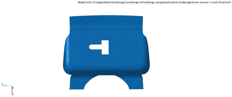
Figure: Latch reinforcement mesh
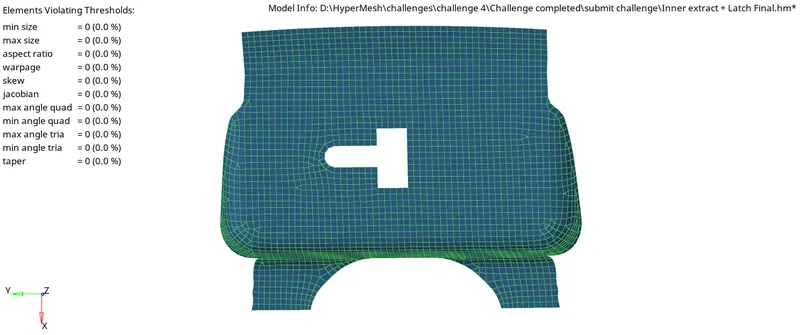
Figure:Latch reinforcement qualityindex
Figure:Latch reinforcement Edge check
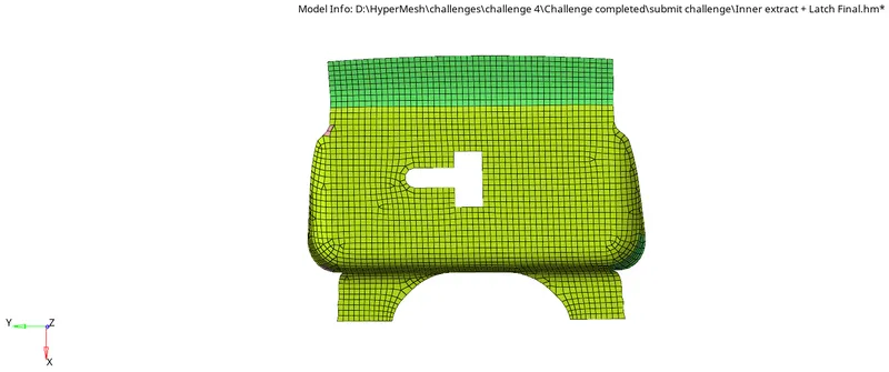
Figure:Latch reinforcement Elements to Surface edge check
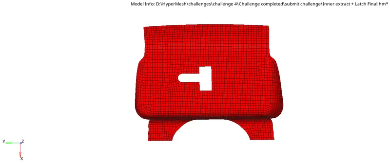
Figure:Latch reinforcement Normals check
5.2 Inner extract:
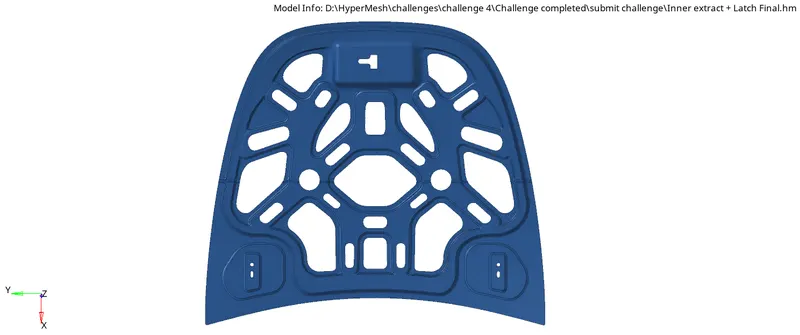
Figure: Inner extract mesh
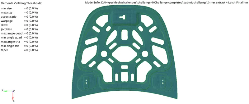
Figure:Inner extract qualityindex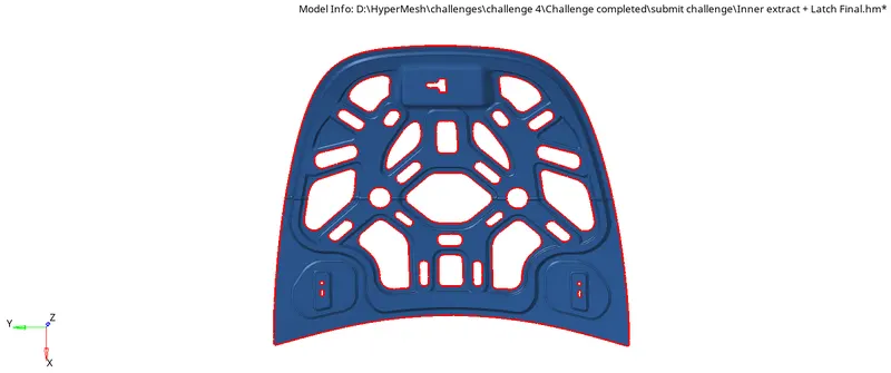
Figure:Inner extract Edge check
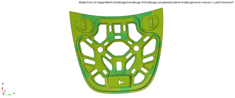
Figure:Inner extract Elements to Surface edge check
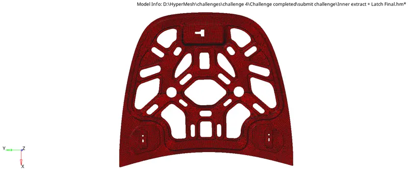
Figure:Inner extract Normals check
5.3 Outer extract:
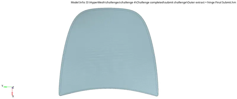
Figure:Outer extract mesh
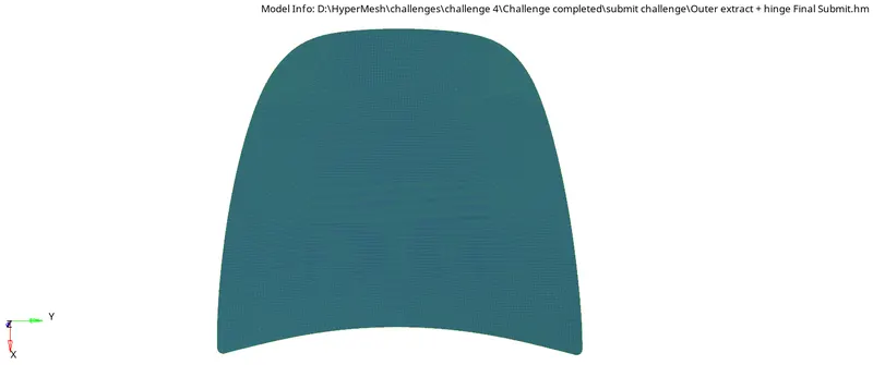
Figure:Outer extract qualityindex
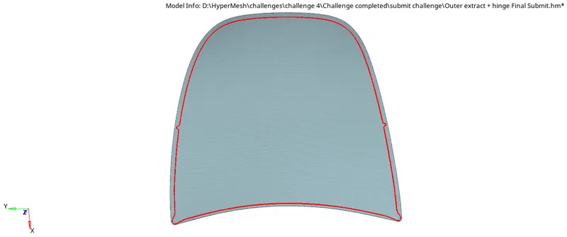
Figure:Outer extract Edge check
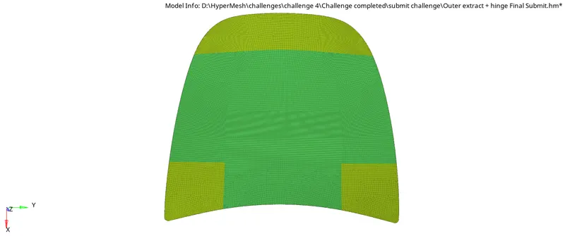
Figure:Outer extract Elements to Surface edge check
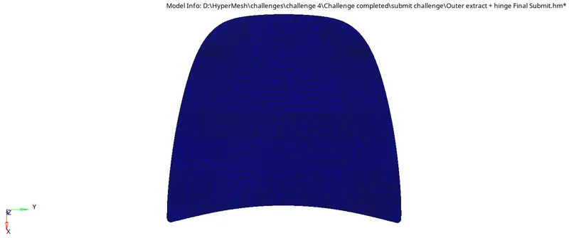
Figure:Inner extract Normals check
5.4 Hinge reinforcement extract:
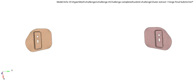
Figure: Hinge reinforcement mesh
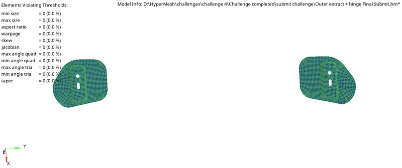
Figure: Hinge reinforcement qualityindex
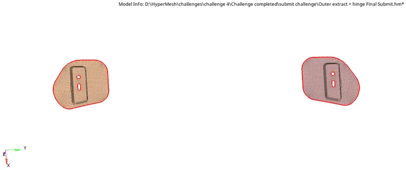
Figure:Hinge reinforcement Edge check
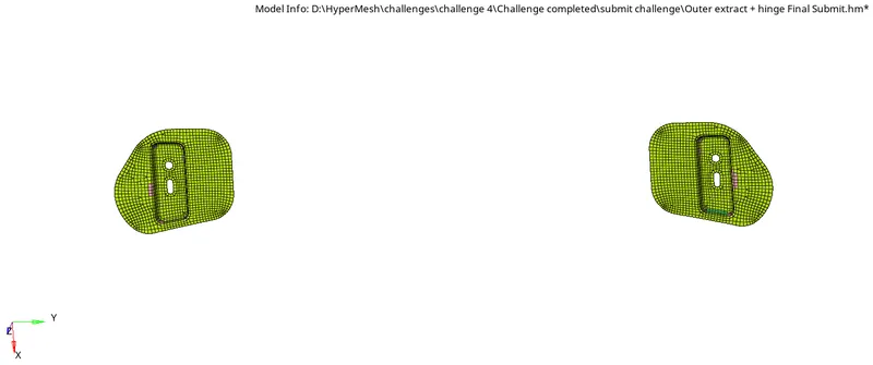
Figure:Hinge reinforcement Elements to Surface edge check
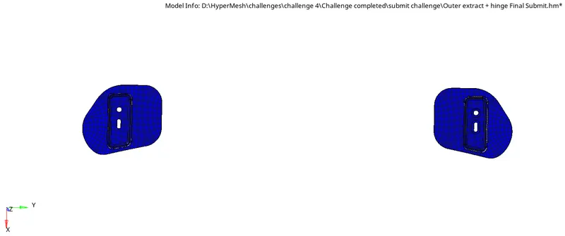
Figure:Hinge reinforcement Normals check
6.Results:
- Extracted the midsurface of each of the four subcomponents[Inner extract,Outer extract,Latch reinforcement extract and Hinge reinforcement extract] of the hood separately using "skin offset" option.
- Meshed the midsurfaces as per the given quality criteria.
- Validated the meshed components against the given quality criteria using the "qualityindex" and various model check options available in HyperMesh.
7.Conclusions:
- This challenge helped me to have a better understanding of how to mesh complex geometries and how different types of meshes are used for different applications.
- It also helped me to understand how to check whether the given mesh satisfies the required quality criteria and how to correct them in case it is deviating from given criteria.
- Since, Iam using Student version of HyperWorks software, it is not possible to save a file exceeding a node limit of 100000. Hence, I couldn't save the entire component in a single file because of which Inner extract and Latch reinforcement are attached in one file and Outer extract and Hinge reinforcement are included in a different file.