Week 1 Stress Concentration on a Plate with hole
Stress Concentration on a Plate with hole
1.Aim: : To perform static structural analysis to determine the stress concentration on a plate with holes.
2.Objective:
i.Design a plate with a hole model. (Case 1)
ii.Design a plate with three holes of different diameter. (Case 2)
iii.Determining the maximum deformation and stress developed in both models.
iv.Comparing the result of two cases and deciding which cases to select on analysis and manufacturing point of view.
3.Theory:
Stress concentration is defined as the localization of high stresses due to the irregularities present in the component and abrupt changes of the cross section. In order to consider the effect of stress concentration and find out localized stresses, a factor called stress concentration factor (SCF) is used. It is denoted by Kt and defined as
`K_t=sigma_max/sigma_o`
where `sigma_max="Highest Value of actual stress near discontinuity"` and `sigma_o="Nominal stress(Average stress at minimum cross-section)"`
`K_t=1+2 {"Lateral length of cut/Longitudinal length of cut}"`
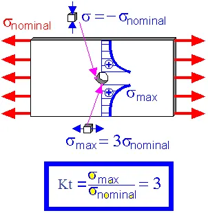
For pinholes that is when width of cut << width of plate, K_t=3.
4.Procedure:
Case 1: Stress Concentration on a Plate with single center hole .
- Open the ANSYS Workbench software. Under the Analysis system select the Static structural and wait for few seconds to pop up the window, which contains Engineering data, Geometry, Model, setup, Solution and Results.
- Rename the static structural as Plate with a hole.
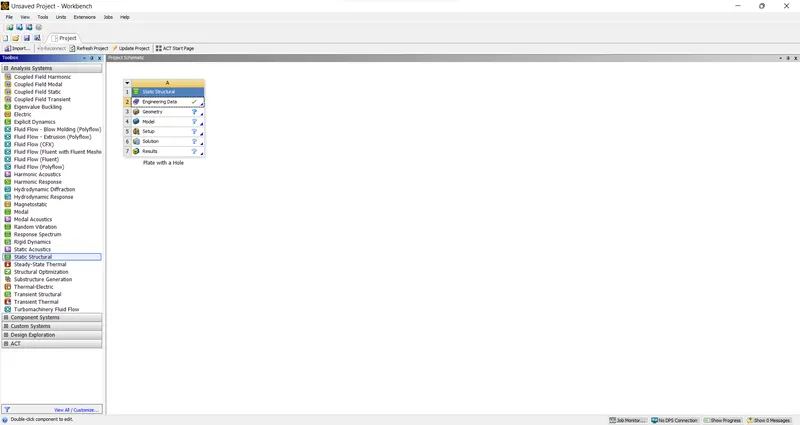
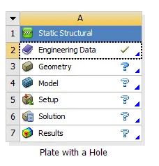
- Update the Default material (Structural steel) to the System, under the Engineering data.
-
Design a rectangular plate with hole by using space claim and assign the Dimensions such as
Plate dimensions:
Length=300mm
Height=120mm
Thickness=30mm
Circular Hole at the center:
Diameter=60mm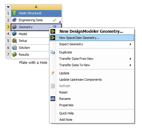
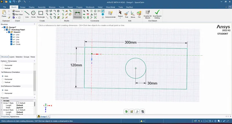
By using pull option assign the thickness of the plate as 30mm.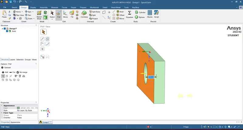
- Update the model by right clicking and edit the Model for meshing.
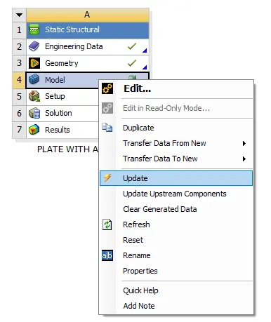
- Wait for few seconds and ANSYS Mechanical will open-up. Mesh the geometry with element size of 2mm and method of solving as tetrahedron element type. Generate the mesh thereafter by right clicking on the Mesh icon.
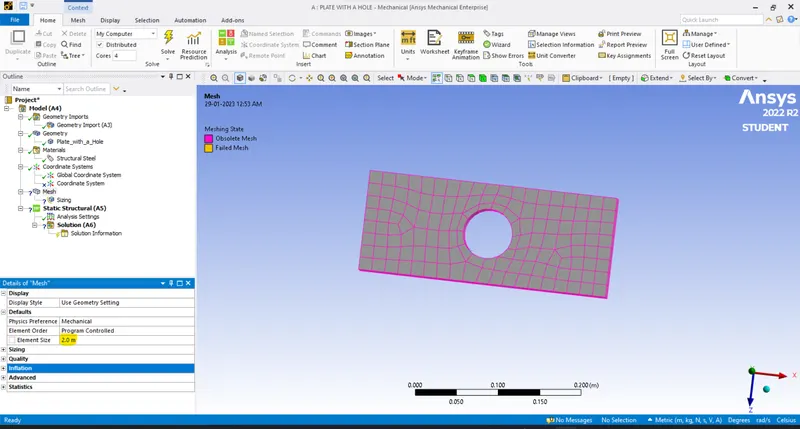
Note: By default the mesh size will be calculated in metres in Ansys. So we have to change it to mm.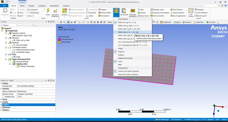
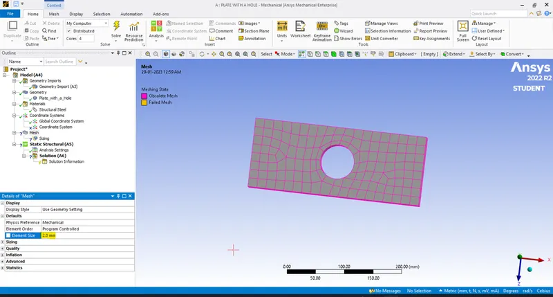
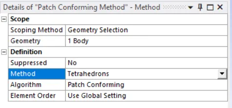
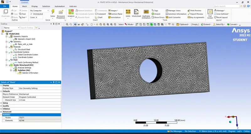
Figure: Final meshed model - In order to get the results we have to fix the left end of the plate by using the fixed support option and apply the tensile force of 500N at right side of the plate.
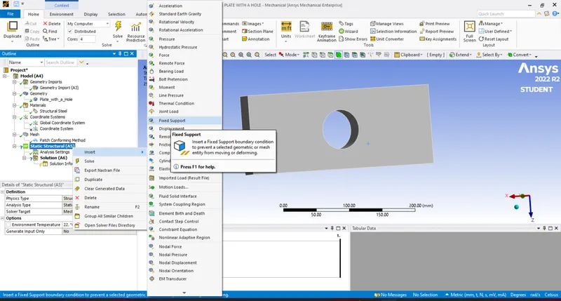
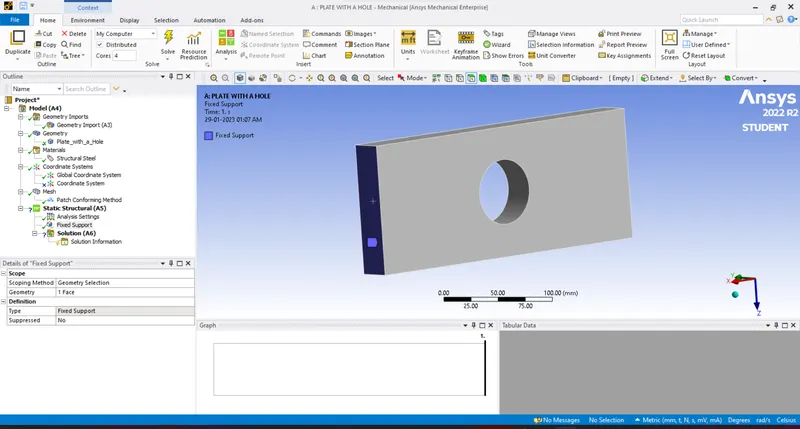
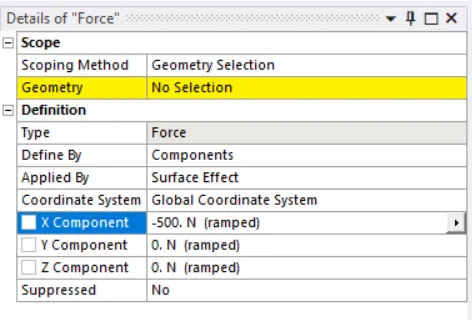
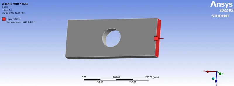
- SOLVE the solution and we can see the simulation run under soluion information.
- Then request for the output results such as Total deformation and equivalent (von-mises) stress. Finally evaluate all the results.
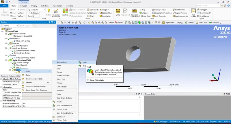
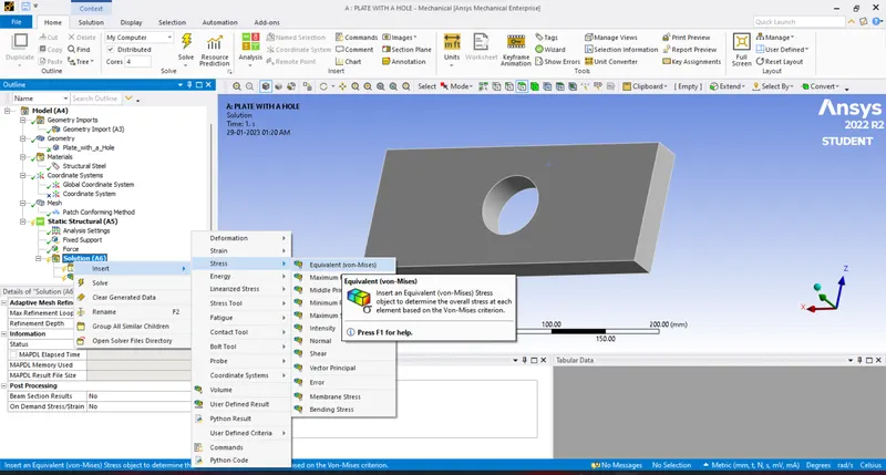
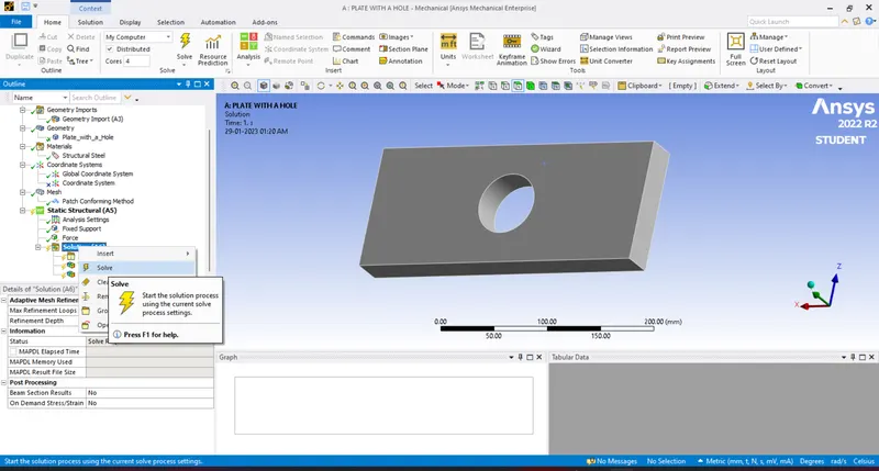
- The Final results for Total deformation and Equivalent von-mises stresses are shown below:
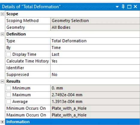
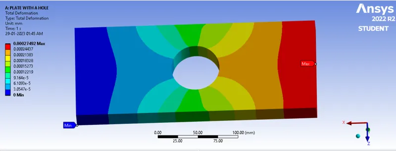
Figure: Total Deformation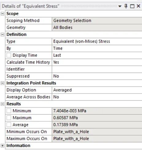
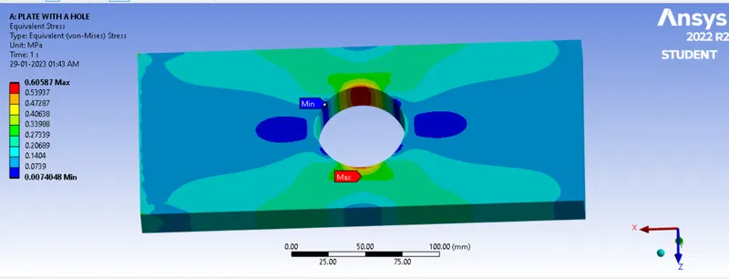
Figure: Equivalent Von-Mises Stress
Case 2: Stress Concentration on a Plate with three holes
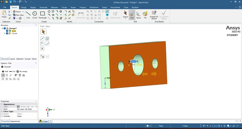
- Follow all the steps as mentioned in case 1. Just add 2 more holes in the plate while generating the geometry in space claim as per the following dimensions:
smaller holes 90mm away from the center
Diameter=30mm
Boundary Conditions:
Plate fixed at left face.
Load of 500N on the right face.
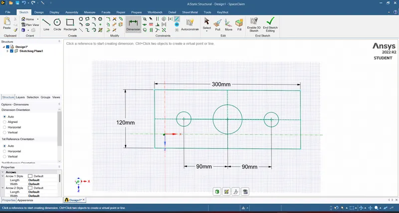
- The Final results for Total deformation and Equivalent von-mises stress are shown below:
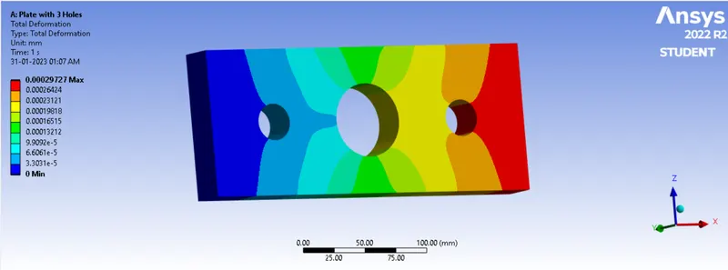
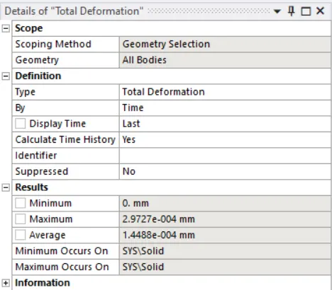
Figure: Total Deformation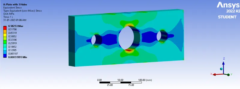
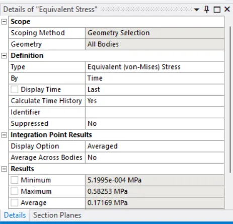
Figure: Equivalent Von-Mises Stress
5.Results:
| Sr.No | Solution | Plate with a hole(Case 1) | Plate with three hole(Case 2) |
| 1. | Total deformation(Maximum) | 2.7492e-004 mm | 2.9727e-004 mm |
| 2. | Total deformation(Minimum) | 0 | 0 |
| 3. | Equivalent stress(Maximum) | 0.60587 Mpa | 0.58253 MPa |
| 4. | Equivalent stress(Minimum) | 7.4048e-003 Mpa | 5.1995e-004 Mpa |
From the above table the deformation in the second case (Stress Concentration on a Plate with three holes) is high when compared to first case(Stress Concentration on a Plate with single hole). Where as For Maximum stress, it will be high in first case(Stress Concentration on a Plate with single hole) when compared with the second case(Stress Concentration on a Plate with three holes).
6.Conclusion:
Selection of Design from the analysis point of view
From the analysis point of view, we can select the case-2 (Stress Concentration on a Plate with three holes)
EXPLANATION:
The main agenda of any analysis is to reduce the stress. Based on that, case-2 is having lower stress when compared with case-1. For that reason we can select case-2 from analysis point of view.
Selection of Design from the Manufacturing point of view
From the Manfacturing point of view, we can select case-1 (Stress Concentration on a Plate with single hole)
EXPLANATION:
The main agenda of any manufacturer is to reduce the wastage of material as well as to reduce the production time. So the first case is very simple in design and requires less time for manufacturing with less wastage of material, where as in case-2 it requires more time for manufacturing as well as wastage of material will be high. For that reason we can select case-1 from Manfacturing point of view.