Week 12:Project-1-Meshing of Door Inner Panel Challenge
SIDE DOOR INNER PANEL MESHING
OBJECTIVE: To extract midsurface of side door inner panel and check quality criteria of 2d mesh.
INTRODUCTION: The side door inner panel model are generally made of acrylonitrile butadiene styrene also called as ABS. It is a thermoplastic polymer. On side door inner panel window control of the car, car lock are placed. Side door inner panel have variable thickness throughout its surface.
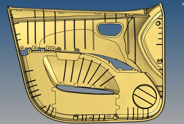
CAD MODEL:-
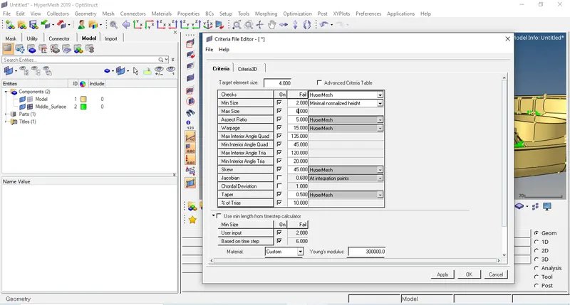
QUALITY CRITERIA:-
Target Element Size= 4 mm.
|
QUALITY CRITERIA |
VALUE |
|
ASPECT RATIO |
5 |
|
SKEWNESS |
45 |
|
WARPING |
15 |
|
TAPER |
0.5 |
|
MIN. LENGTH (mm) |
2 |
|
MAX. LENGTH (mm) |
6 |
|
MIN. ANGLE QUAD |
45 |
|
MAX. ANGLE QUAD |
135 |
|
MIN. ANGLE TRIA |
20 |
|
MAX. ANGLE TRIA |
120 |
|
TRIA % |
10 |
PROCEDURE:-
- First the model is imported using import model option in tab bar in Hypermesh and the required component is separated out and the solid part is deleted.
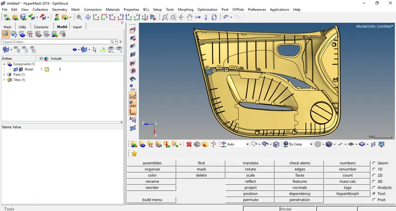
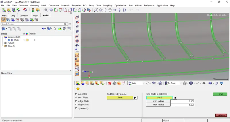
- The model imported needs to be geometrically clean before the midsurfacing is done. The model has surface fillets that needs to be removed using surface fillets option (Geom>defeature>surface fillets).
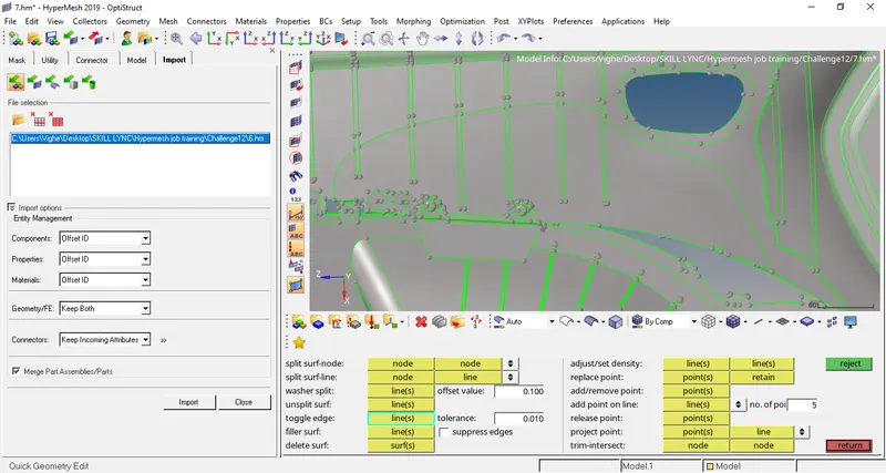
- Toggle out the lines which can make element failed after meshing (Geom>quick edits>toggle lines)
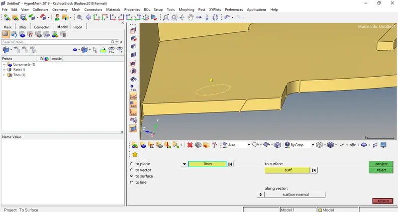
- There are some surface where the main surface to capture is the hole and not elevated surface so first we delete the surface and project the hole on the main surface or base surface using project option (Tools>project>to surface).
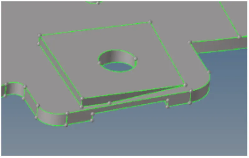
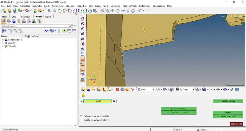
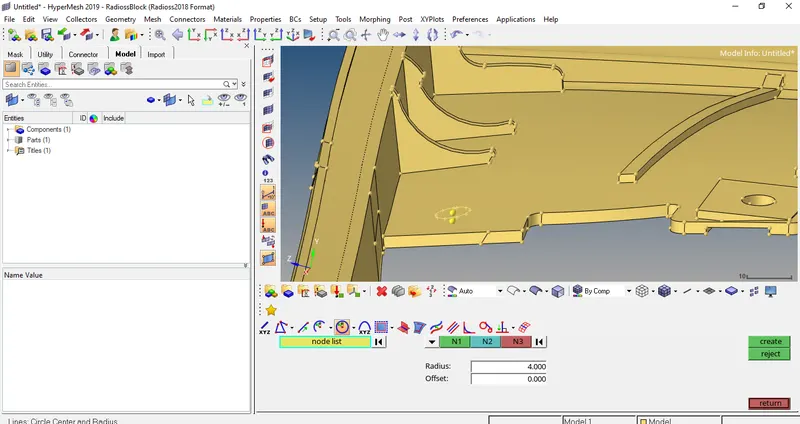
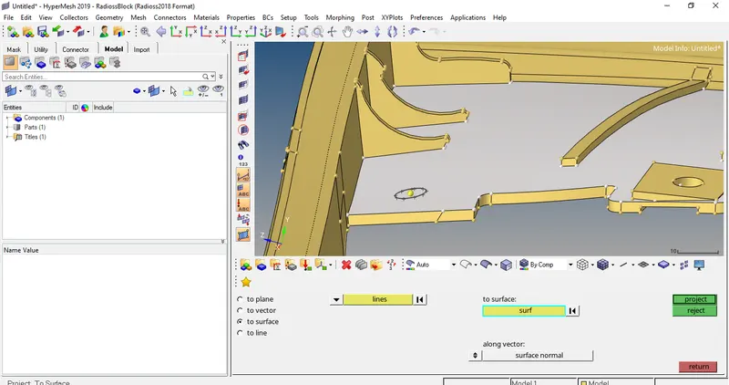
- After projecting the circle on the surface we have to trim the surface with circle as the trim line using surface trim option (Geom>surface edit >surface trim).
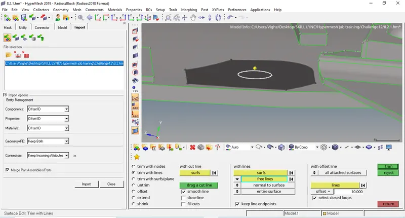
- Repeat the above steps on the other surface capturing the hole is the main idea.
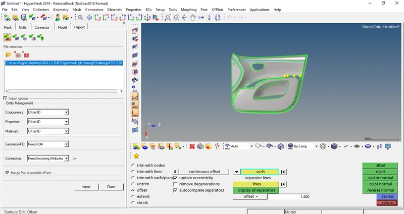
- Since the model has different thickness so instead of auto midsurface we do manual misdurface. In manual midsurface offset of the surface is done at the centre distance (Geom>Surface edit>Offset).
- Now we do manual midsurface of body using offset option (Geom>Surface edit>Offset).
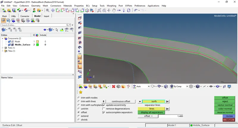
- The other parts of the model have different thickness so measure those parts thickness and then offset it using surface offset option (Geom>Surface edit>Offset).
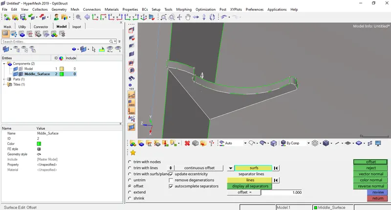
- The ribs offsetted are not properly projected on the main surface so this can be done using two options. First by extending the ribs line to the surface using extend option (Geom>Surface edit>Extend).
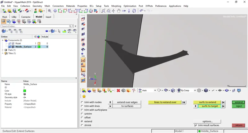
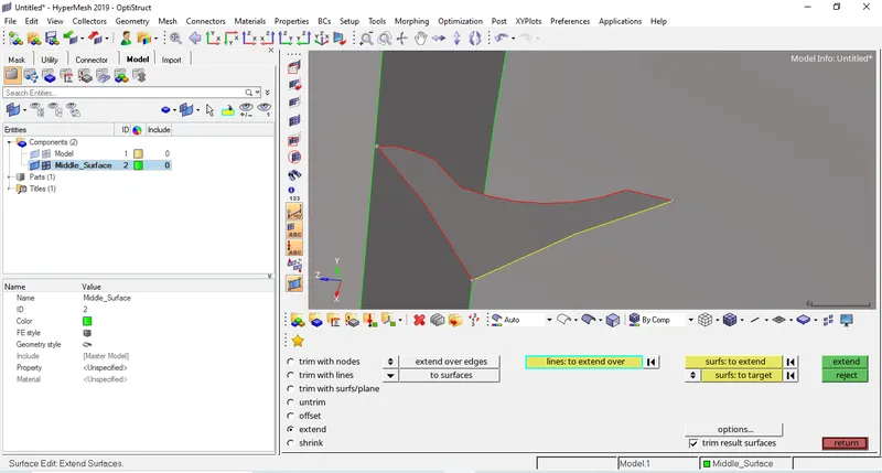
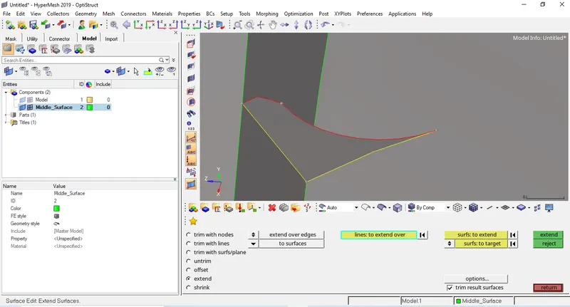
- Second method that can be use is by dragging the line by some dimension in required direction using drag along option (Geom>lines>drag along) and then trimming the extended surface by the base surface using surface trim option (Geom>surface edits>trim with surfs/plane) and then deleting the extended trim surface.
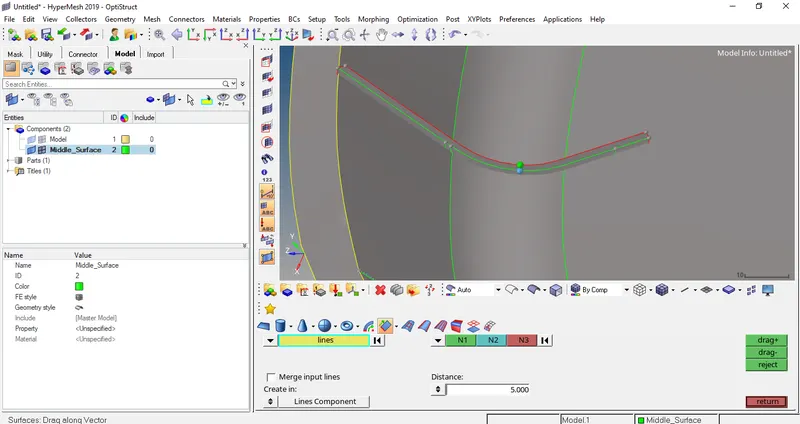
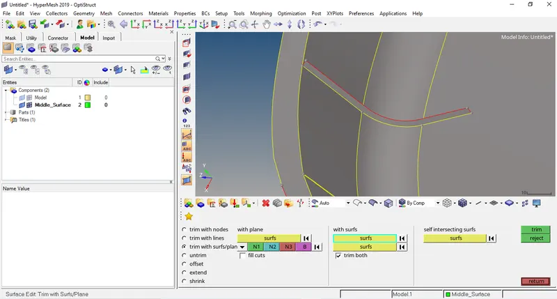
- Now we have insert the given mesh criteria in preference option in tab bar.
- Now we have to mesh body with target element= 4 mm (2D>automesh).
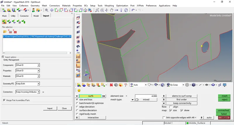
- The mesh created is not proper as the parts gets complex so the mesh is improved by changing the number of nodes but still some mesh elements are still not proper so those elements are meshed again (2D>automesh).
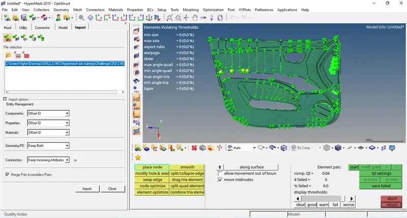
- To check the quality of meshing the quality criteria option is opened and the highlighted elements are improved using QI tools given till all the elements are unhighlighted. (2D>Quality Criteria).
- After cleaning up all the elements check whether there are no failed elements in (2D>Quality Criteria).
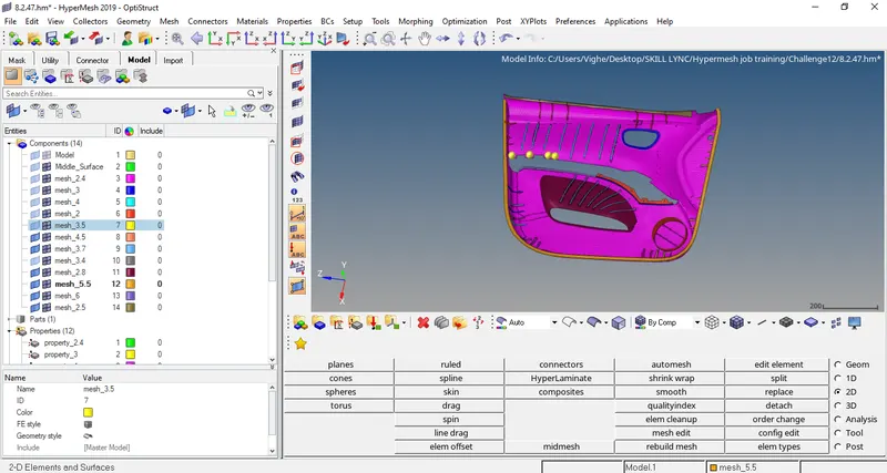
- Since the model has variable thickness we have to create new components with new properties having the required various thickness and then assigning that property to that component. Meshes with different thickness are placed in the new components using organize option (Tools>Organize>Collectors).
CONCLUSION: The project was done successfully.