CREATING OF 1D ELEMENTS LIKE ROD, BAR AND BEAM ON MIDSURFACES OF PARALLEL BRACKET
CREATING OF 1D ELEMENTS LIKE ROD, BAR AND BEAM ON MIDSURFACES OF PARALLEL BRACKET
OBJECTIVE: To create 1D elements like rod, bar and beam on midsurfaces of parallel bracket.
CAD MODEL:-
The CAD model consists of two parallel brakets with five holes each.
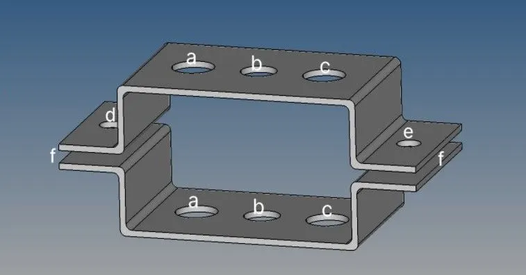
PROCEDURE:-
- First the geometry which is in IGS format is imported in Hypermesh.
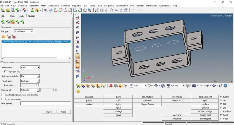
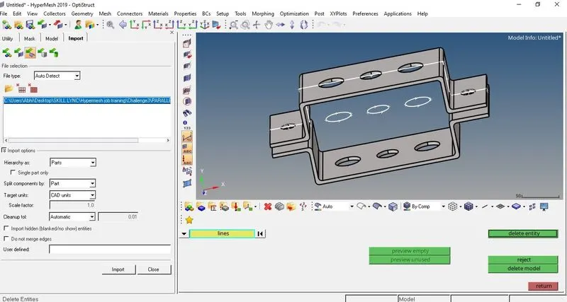
- All the lines in the geometry are deleted using Delete option in Tool bar.
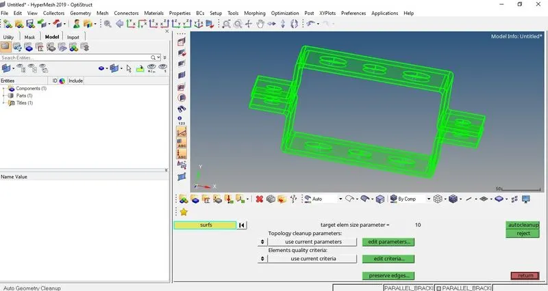
- Autoclean of the geometry is done using Autocleanup option in main tool bar(Geom>autocleaunup).
- Two components are created and named Bracket_1 and Bracket_2 in tab bar and then completed component separated and moved in Bracket_1 and Bracket_2 using Organize option in main tool bar (Tools>Organize>Move). Note:- First Bracket_1 is created and moved and then Bracket_2 is created and moved.
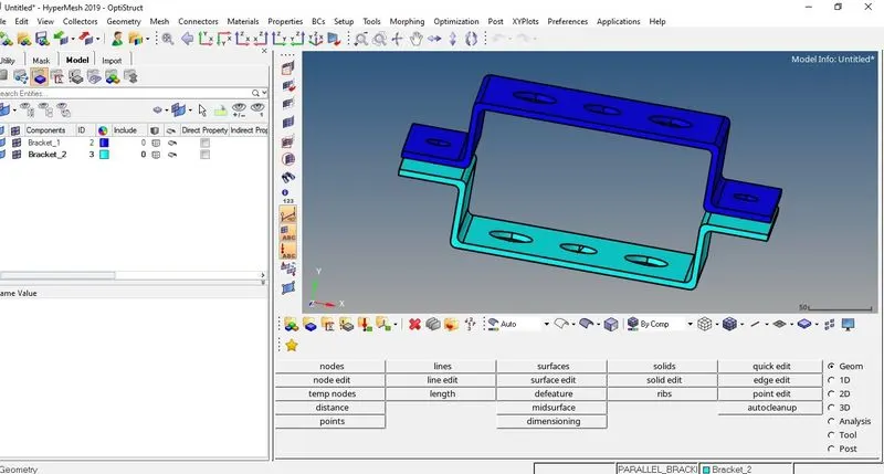
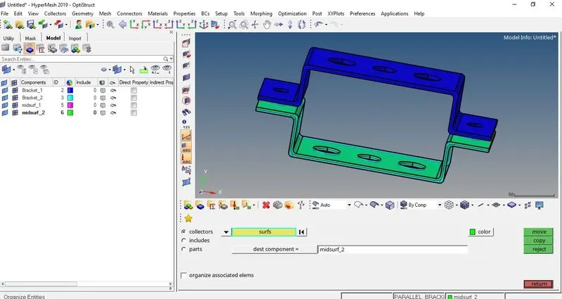
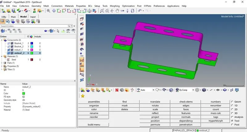
- Midsurfaces of the two brackets are created. Midsurface option is used to create midsurface of the solid for meshing since meshing of solid takes long time and hence longer processing time during analysing midsurface is preferred. Midsurface option is used from main tool bar and midsurf_1 is created and the Bracket_1 is selected (Geom>midsurface>autoextraction>create). The same process is used to create midsurface of Bracket_2 and is named as midsurf_2. The colours of the midsurfaces are changed in tab bar.
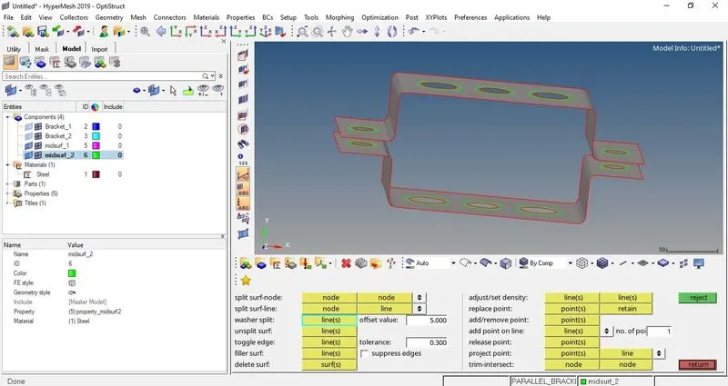
- Before the meshing washer split option is used on the holes of both the brackets with offset value of 5 mm (Geom>quick edit>washer split).
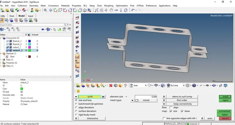
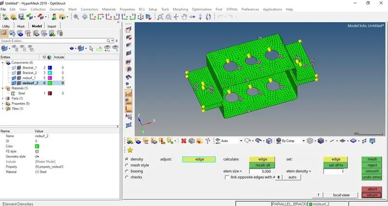
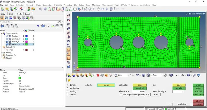
- Meshing of the bracket surfaces is done using automesh option with mixed elements of size 5 mm is done from main tool bar (2D>automesh). The nodes of holes and the offset holes are adjusted so that meshing is proper near the holes.
- Rbe2 link is created on ‘a-position’ of bracket 1 with only translational degree of freedom (1D>Rigids>create). To make sure the degree of freedom are properly implemented on the element we have to go select the link and then go to update option in rigids and select dof to update. (1D>Rigids>update).
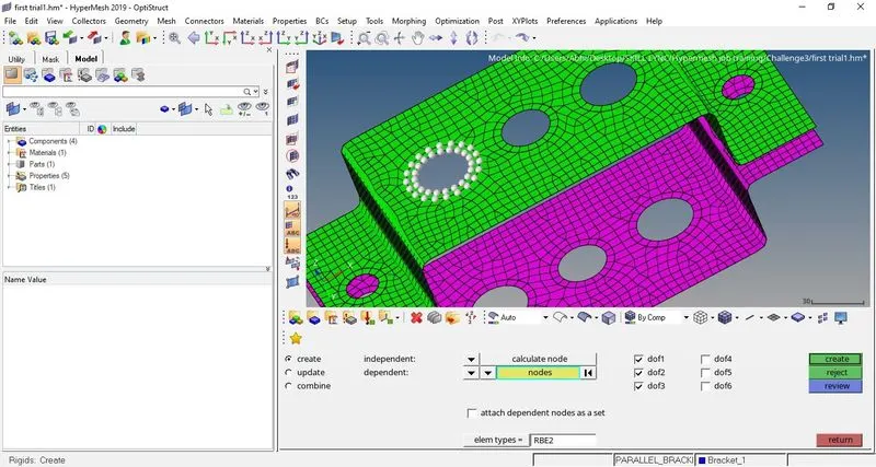
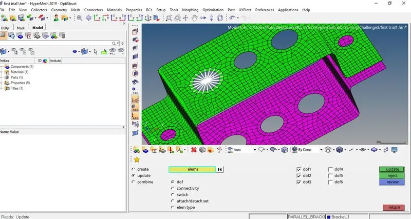
- Similar as the above, Rbe2 link is created and updated at the ‘a-position’ of bracket 2.
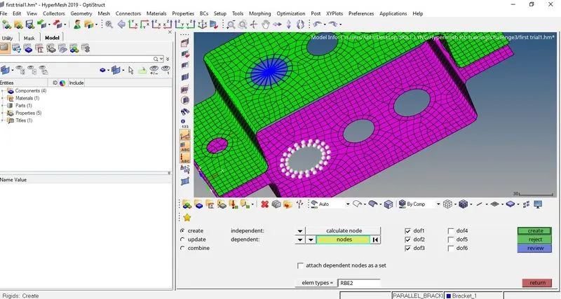
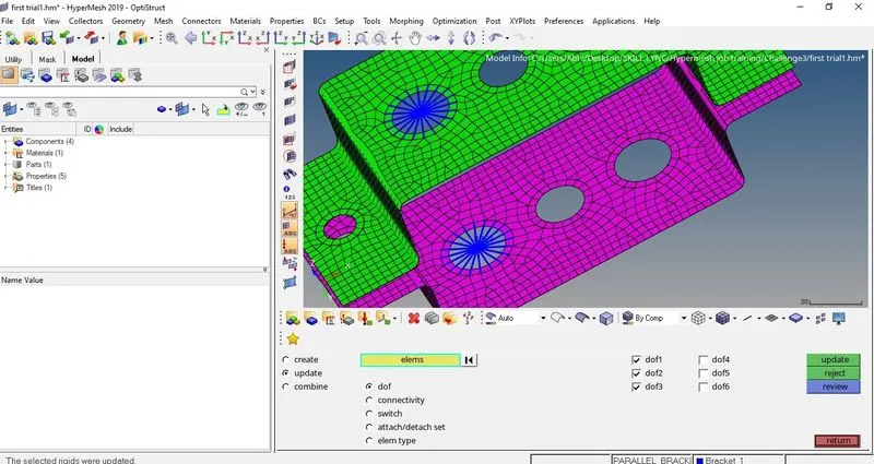
- Rbe3 link is created on ‘b-position’ of bracket 1 with all degree of freedom (1D>Rbe3>create). To make sure the degree of freedom are properly implemented on the element we have to go select the link and then go to update option in Rbe3 and select dof to update. (1D>Rbe3>update).
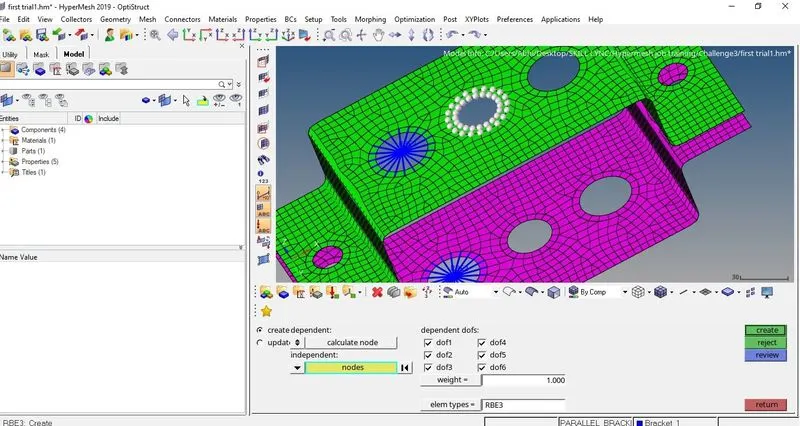
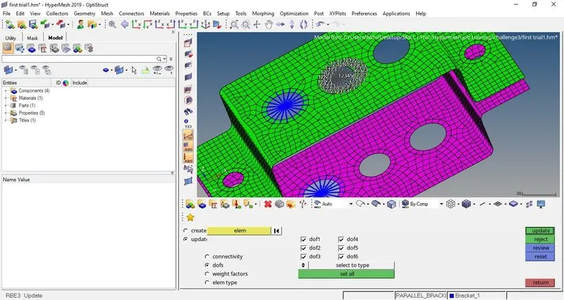
- Similar as the above, Rbe3 link is created and updated at the ‘b-position’ of bracket 2.
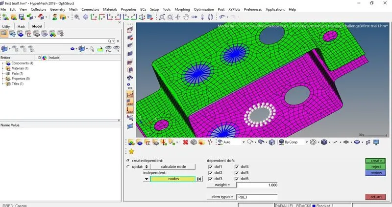
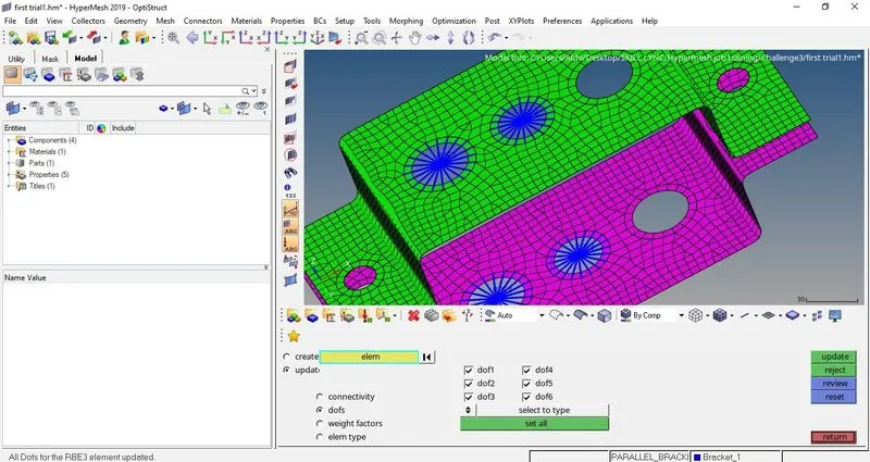
- Rbe3 link is created on ‘b-position’ of bracket 1 with only X and Y degree of freedom (1D>Rbe3>create). To make sure the degree of freedom are properly implemented on the element we have to go select the link and then go to update option in Rbe3 and select dof to update. (1D>Rbe3>update).
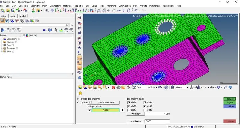
- Similar as the above, Rbe3 link is created and updated at the ‘b-position’ of bracket 2.
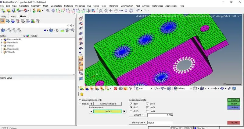
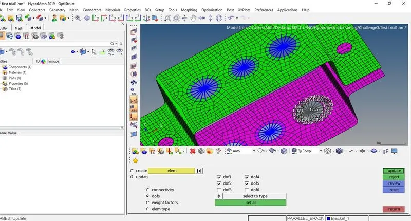
- Masses- Rbe2 links are created on ‘d & e position’ of bracket 1 (1D>Rigids>create). Masses are created at the centre node of Rbe2 links at ‘d & e position’ of magnitude 10 (1D>Masses>create).
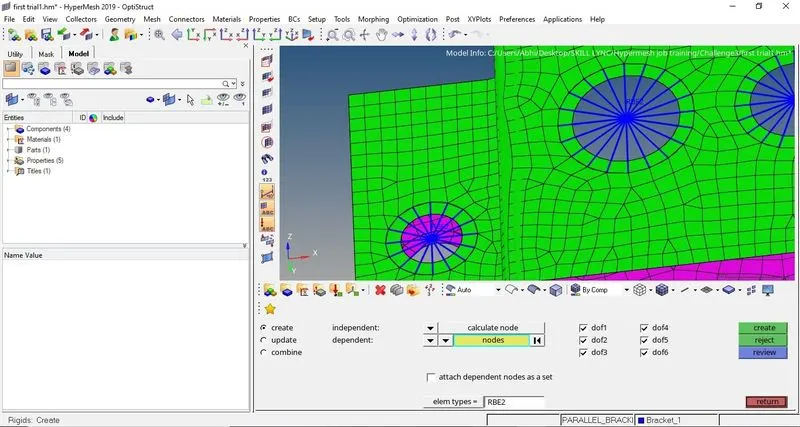
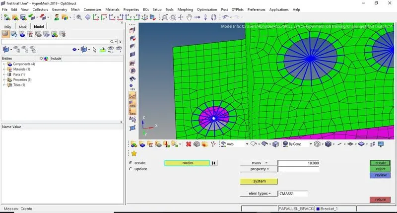
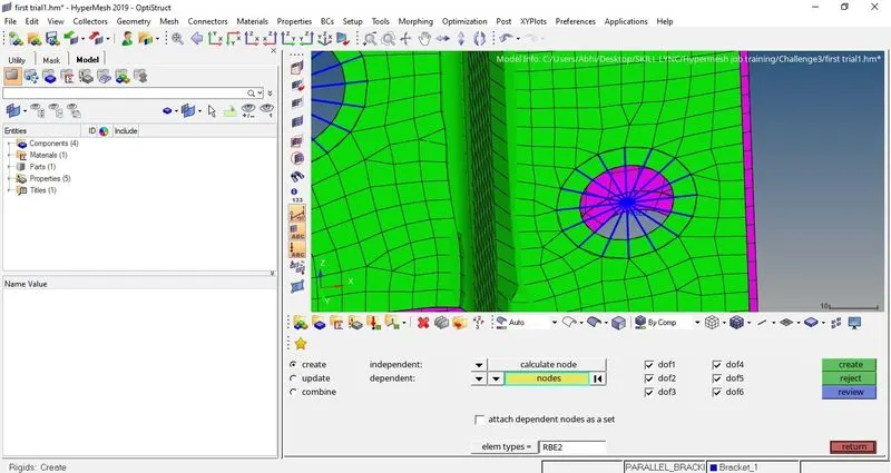
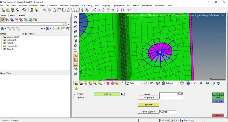
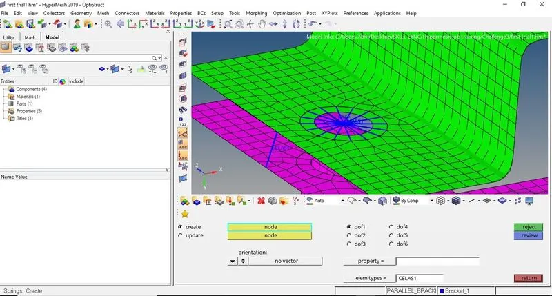
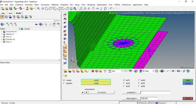
- Spring- springs are created at the ‘f-position’ of the brackets. Two nodes of the brackets are selected one at each bracket and the spring is created. This is applied to both ‘f-position’ of the brackets (1D>springs).
- Hyperbeam- Hyperbeam option is used create cross section of elements to be created between links (1D>HyperBeam).
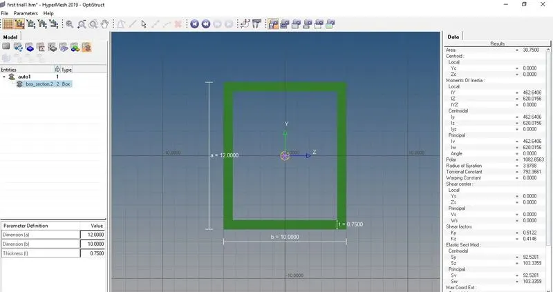
- HyperBeam option is used to create Box cross section element of dimensions a= 12 mm, b= 10 mm, thickness (t) = 0.75 mm at ‘a-position’ of brackets 1 and 2. First from 1D option HyperBeam is selected and then standard section option is used with HYPER BEAM as standard section library and thinwalled box as standard section type to create the element and the name of the element is changed to Rod_section (1D>HyperBeam> standard section option(HYPER BEAM)> standard section type(thinwalled box)>create).
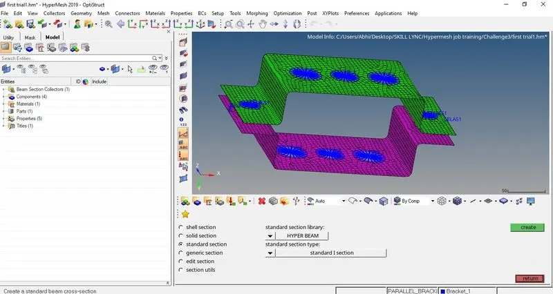
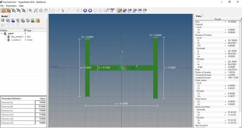
- HyperBeam option is used to create I cross section element of dimensions a= 8 mm, b= 10 mm, c= 8.5 mm, thickness (t1) = 0.75 mm, thickness (t2) = 0.6 mm, thickness (t3) = 0.6 mm at ‘b-position’ of brackets 1 and 2. First from 1D option HyperBeam is selected and then standard section option is used with HYPER BEAM as standard section library and standard I section as standard section type to create the element and the name of the element is changed to Beam_section (1D>HyperBeam> standard section option(HYPER BEAM)> standard section type (standard I section)>create).
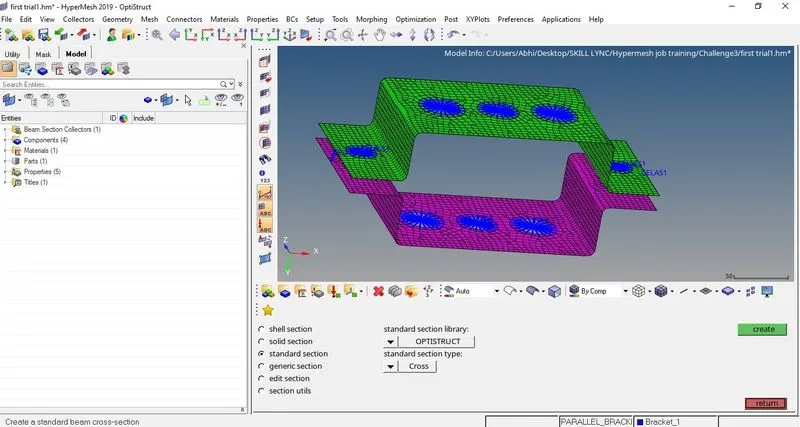
- HyperBeam option is used to create ‘CROSS’ cross section element of dimensions DIM1= 5 mm, thickness DIM2= 1.2 mm, DIM3= 10 mm, thickness DIM4 = 1.2 mm at ‘c-position’ of brackets 1 and 2. First from 1D option HyperBeam is selected and then standard section option is used with OPTISTRUCT as standard section library and CROSS as standard section type to create the element and the name of the element is changed to Bar_section (1D>HyperBeam> standard section option (OPTISTRUCT)> standard section type (CROSS)>create).
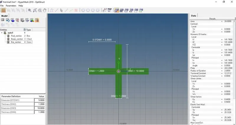
- In tab bar material is created and is named as steel. To create property for rod, beam and bar, first in tab bar the properties are created and steel is selected as material for all three and then the card image option and beamsec option is changed for all three respectively. [Card image- Rod>PROD, beam>PBEAM, bar>PBAR], [beamsec- Rod>Rod_section, beam>Beam_section, bar>Bar_section].
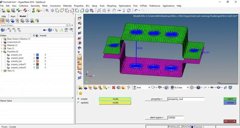
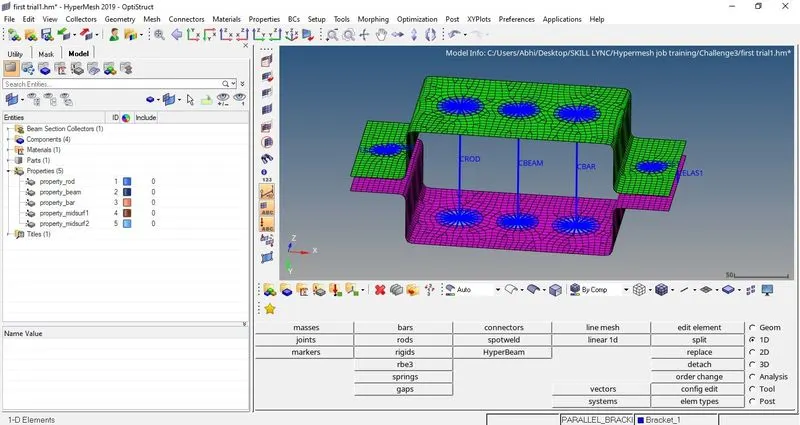
- Rod element is created at the ‘a-position’ using rod option on main tool bar. From 1D option rods is selected and the centre nodes of ‘a-position’ of both brackets is selected and in elem type CROD option is used and then the update option is used to make sure that the rod’s property is implemented (1D>rods>create/update).
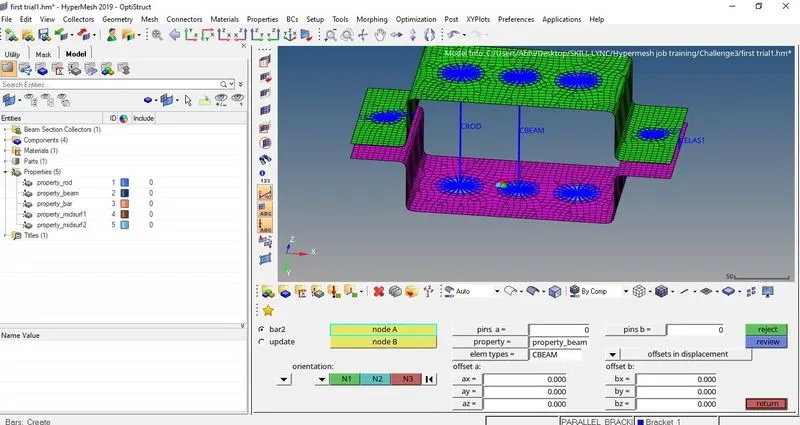
- Beam element is created at the ‘b-position’ using bars option on main tool bar. From 1D option bars is selected and the centre nodes of ‘b-position’ of both brackets is selected and in elem type CBEAM option is used and then the update option is used to make sure that the beam’s property is implemented (1D>bars>create/update).
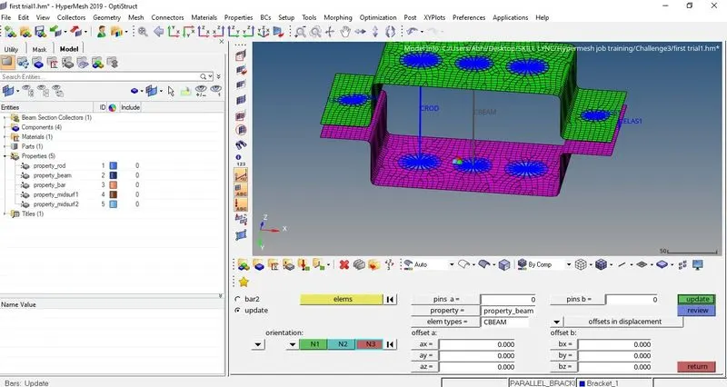
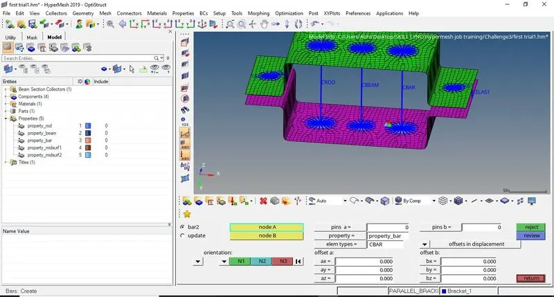
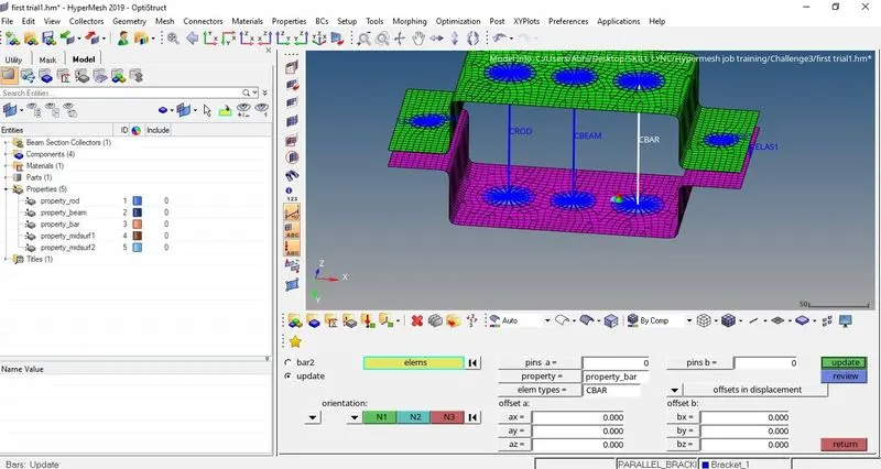
- Bar element is created at the ‘c-position’ using bars option on main tool bar. From 1D option bars is selected and the centre nodes of ‘c-position’ of both brackets is selected and in elem type CBAR option is used and then the update option is used to make sure that the bar’s property is implemented (1D>bars>create/update).
FINAL MODEL IMAGE-

Conclusion:-
Midsurfaces was successfully extracted and 1D elements like rod, bar and beam were created on midsurfaces of parallel brackets successfully.