Assignment 2-RADIOSS Engine File Editing & 3D Meshing Challenge
RADIOSS Engine File Editing & 3D Meshing
Objective:-
- To calculate speed of sound through steel and critical timestep for the given length.
- To edit engine file with critical timestep and the frequency at which output plots are generated (20 steps).
- To 3D mesh housing assembly with the given criteria.
- To 3D mesh arm bracket with the given criteria.
Questions:
- Check the material properties of the rail component and calculate the speed of sound in steel rail=_______
- Import the FIRST_RUN_0000.rad file using File>solver deck>File- FIRST_RUN_0000.rad>import
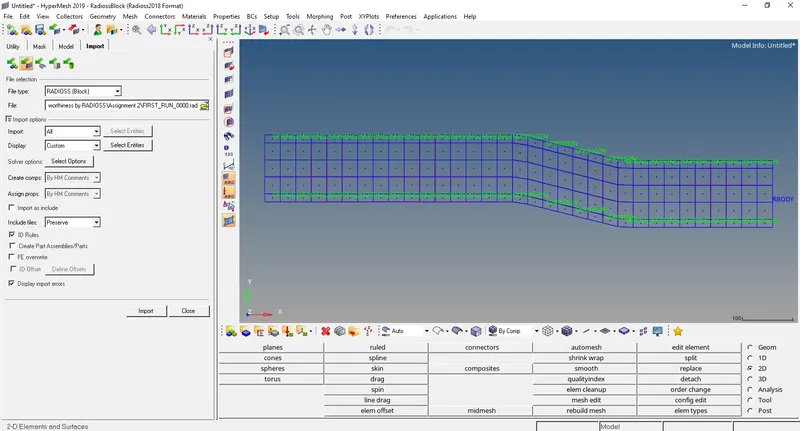
- Now go to model tree>material>steel
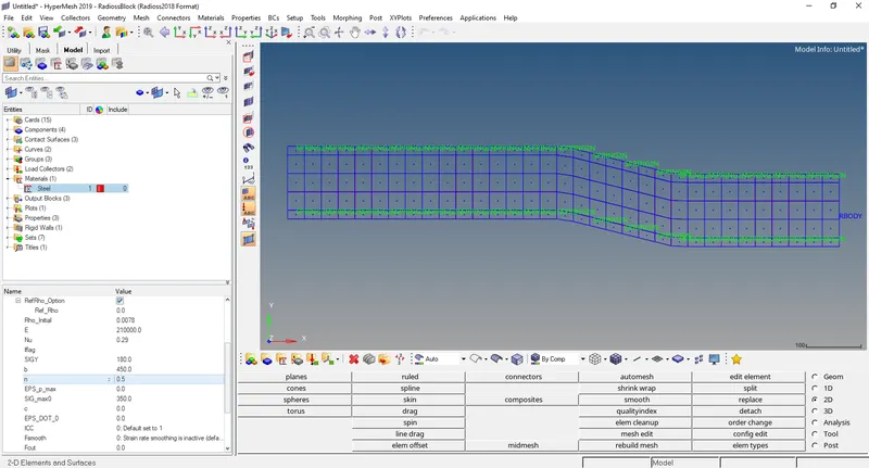
- Another way of checking the material properties is by opening the FIRST_RUN_0000.rad file in notepad.
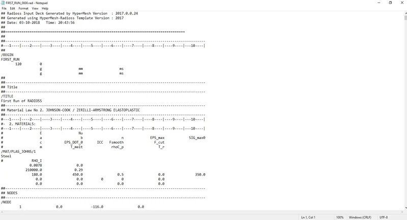
Here the Unit system used is g-mm-ms
Young’s Modulus E=210000 N/mm2
Density = 0.0078 mm3
Poissons ratio= 0.29
Speed of sound c=`√E/ρ` =`√210000/0.0078` = 5188.74 mm/ms
- The length of the rail is about 1000 mm. Calculate the time takes for a shock wave to travel from one end of the rail to the other.
Length of the rail =1000 mm
Time taken by shockwave = (length of rail)/ (speed of sound) = 1000/5188.74 = 0.1927 ms
- Time for sound to travel length of rail Ts = 1927 ms
4.Edit the engine file so that the stress wave can be monitored, moving from one end of the rail to the other during impact -this will require a termination time equal to the time it takes for the sound to travel the length of the rail(set on/RUN card)
- Import the FIRST_RUN_0000.rad file using File>solver deck>File- FIRST_RUN_0000.rad>import
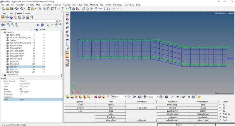
- Now change the Tstop value from 60 to 0.1927 by Model tree>Cards>ENG_RUN
- Now change the Tfreq value from 1 to 0.009635 by Model tree>Cards>ENG_ANIM_DT
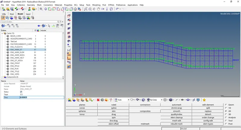
- Now go to Analysis>Radioss
We have to select a location to save the file and then click on Radioss
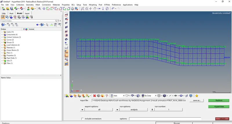
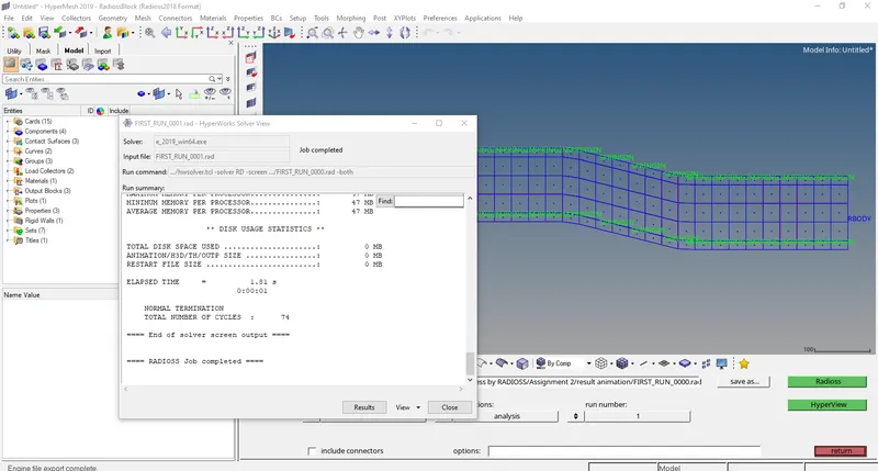
- After the earlier step a window will pop up and tell that output has been generated.
- Set the frequency of animation output to a time that will give 20 animation steps (/ANIM/DT)
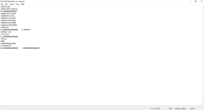
Time related to frequency of animation Tfreq = Ts/ (Animation steps) = 0.1927/20 = 0.009635
- Now change the Tfreq value from 1 to 0.009635 by Model tree>Cards>ENG_ANIM_DT
- Another way to change the value is to open FIRST_RUN_0001.rad in notepad
- Now we see in the folder where FIRST_RUN_0000.rad file is saved that there are 20 animation files.
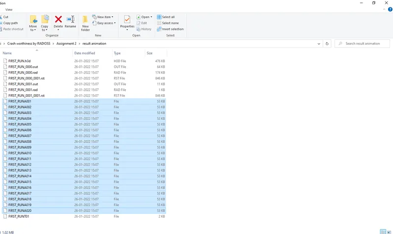
- Change /print -10.
- Change the N_print value to 10 by Model tree>Cards>ENG_PRINT
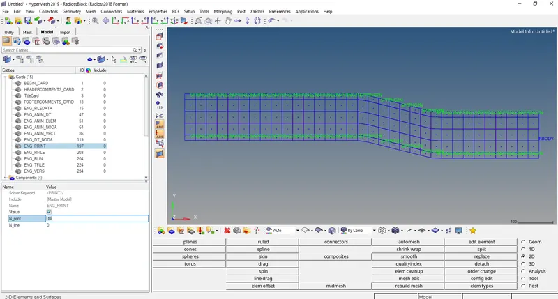
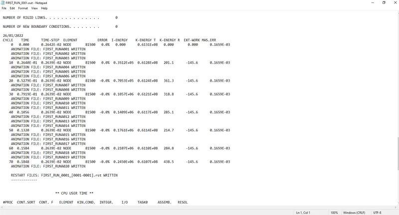
- To verify that the change/ print value is 10 open the FIRST_RUN_0001.out and see that difference between each consecutive cycle is 10
7. 3d meshing tetra mesh and hex mesh
- Repeat class examples and, maintain the quality.
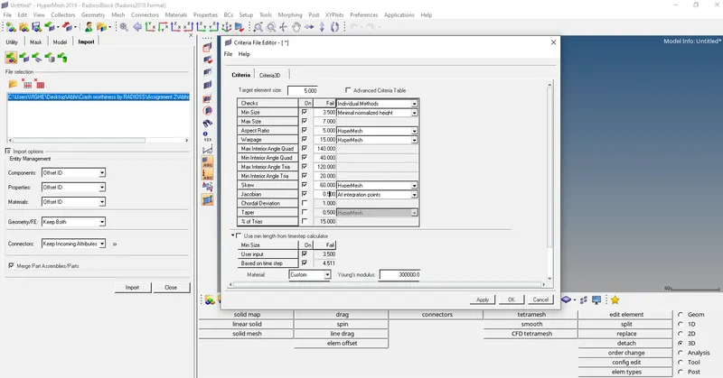
- Target tet size=5mm,hex size=10mm,tet collapse=0.15.
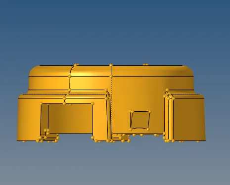
HOUSING:-
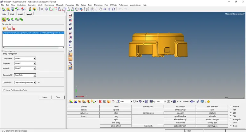
MODEL:-
Procedure:-
- Import the model using File>solver deck>import
- Put the given elemental criteria in Preference>criteria file edit.
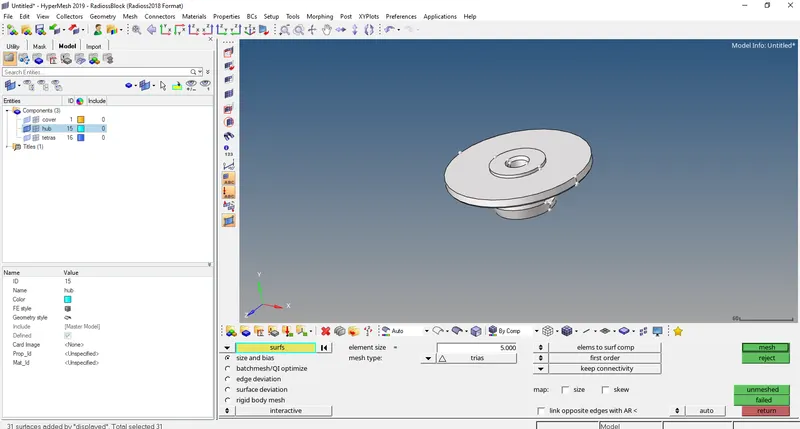
- Now let’s apply 2D tria mesh on the hub using (2D>automesh) and hide the cover
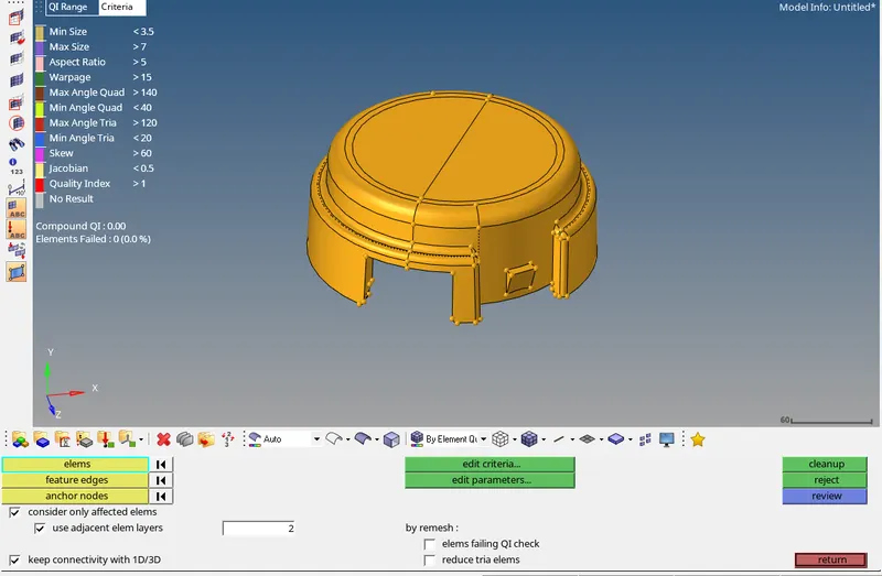
- Check the quality criteria of the 2D mesh using Tool>Check elems
- To 3D mesh the hub go to 3D>tetramesh.
First we have to give the parameters in 3D>tetramesh> tetramesh parameters
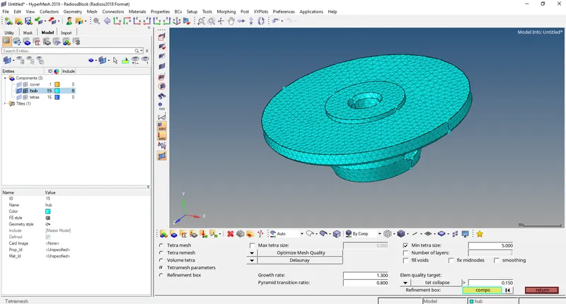
Now go to 3D>tetramesh>Tetra mesh and mesh the hub
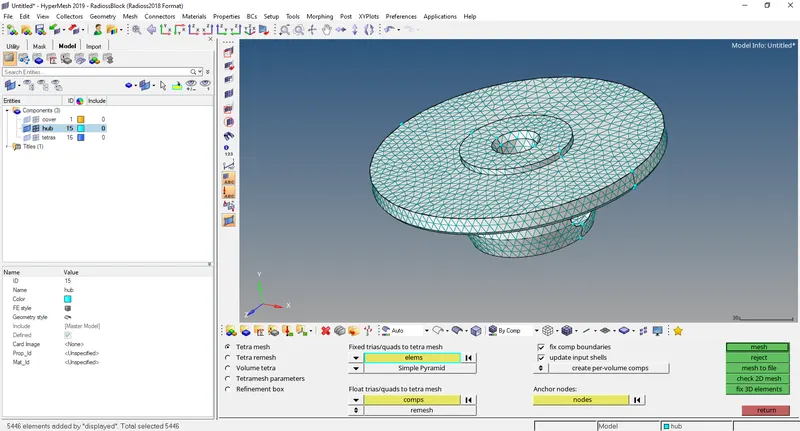
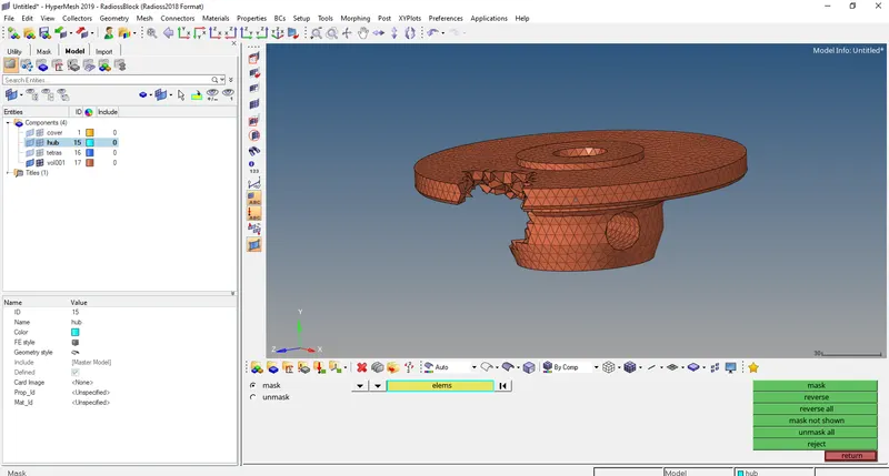
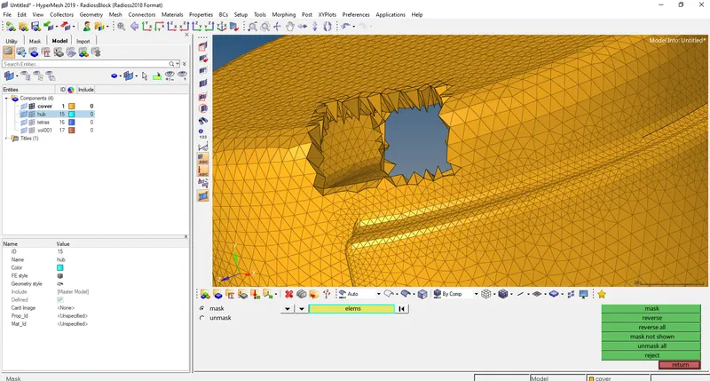
- Now check whether the 3D elements are formed or not go to (Tools>Mask) and mask some elements
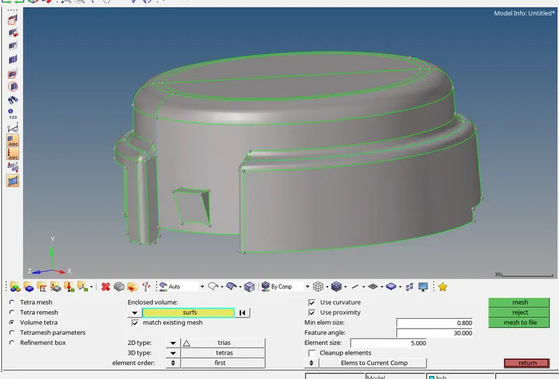
- Now we have to volume tetra mesh the cover to do that go to 3D>tetremesh>Volume tetra
- Now check whether the 3D elements are formed or not go to (Tools>Mask) and mask some elements
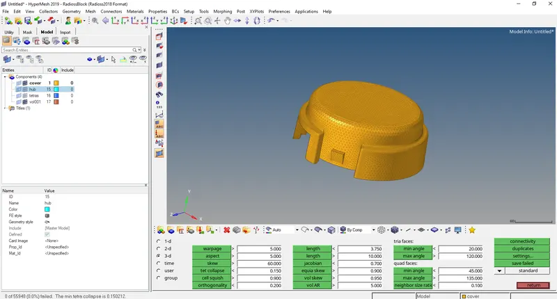
- Let’s check the quality criteria of the 3D mesh go to Tools> Check elems> tet collapse
ARM BRACKET:-
MODEL:-
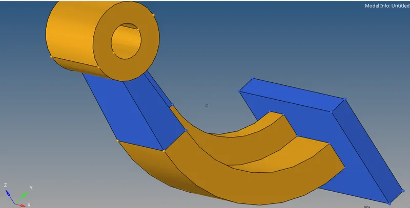
Procedure:-
- Import the model using File>solver deck>import
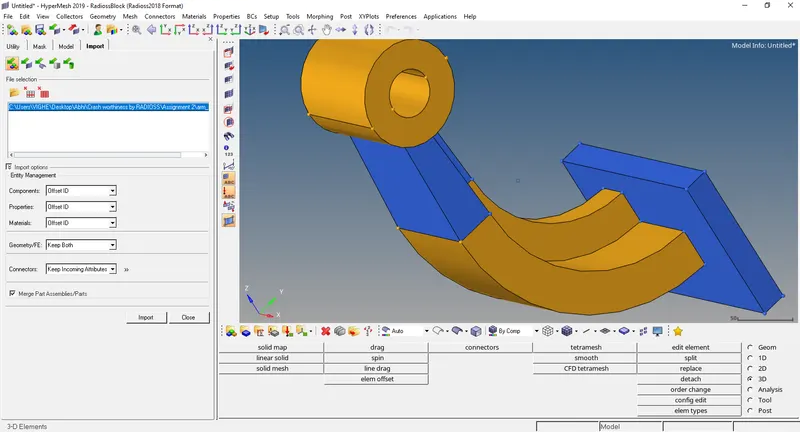
- Put the given elemental criteria in Preference>criteria file edit.
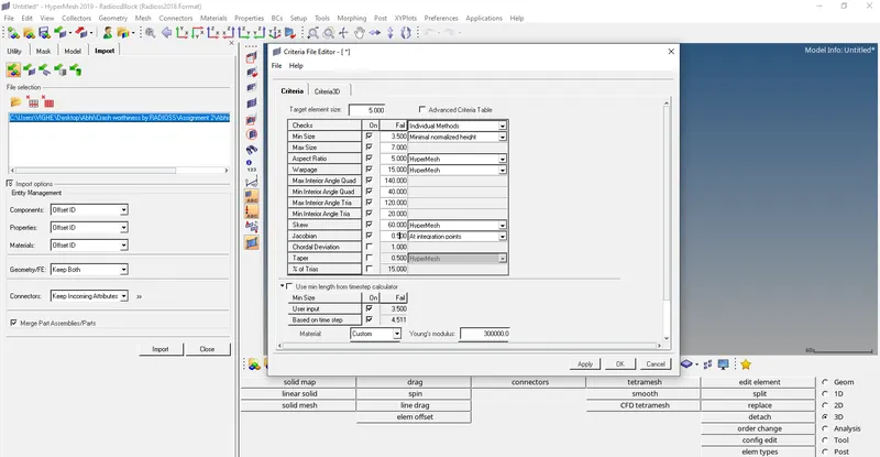
- Now we to do 2D mesh of the base using 2D>automesh and make sure there are no tria elements.
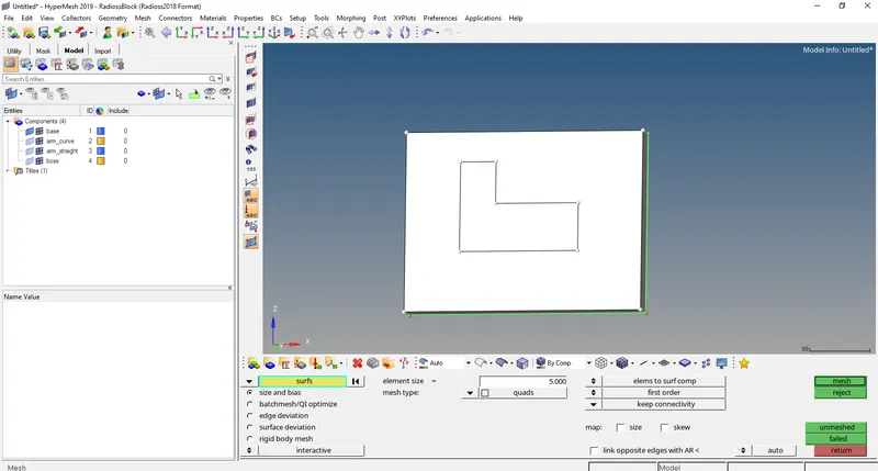
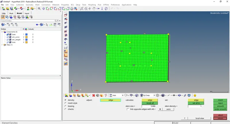
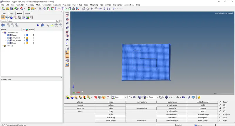
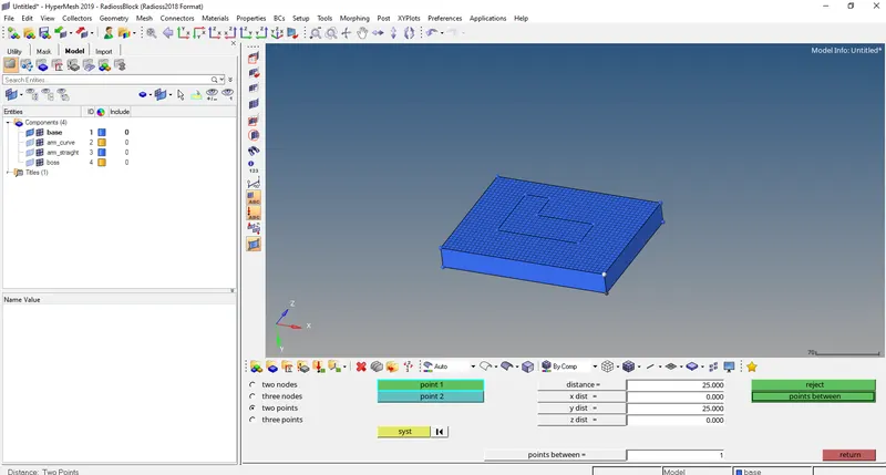
- Before 3D mesh lets measure the height of the base using Geom>distance>two points
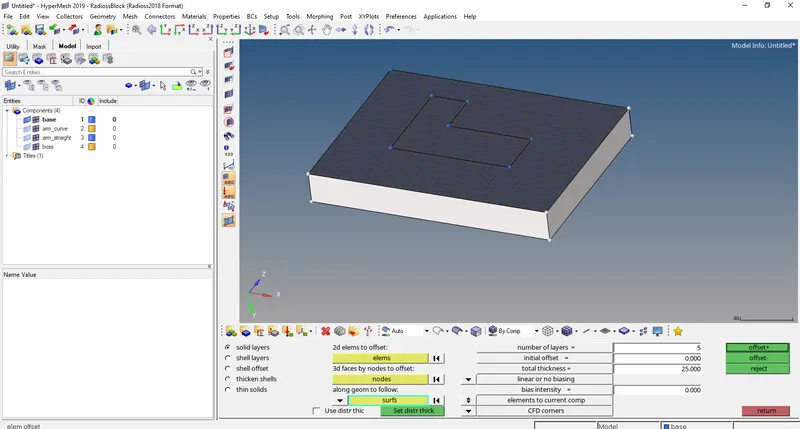
- Now to do 3D mesh go to 3D>elems offset>solid layers
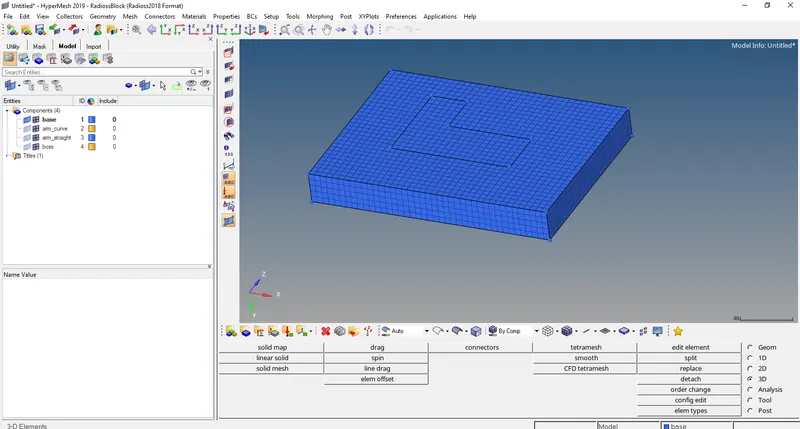
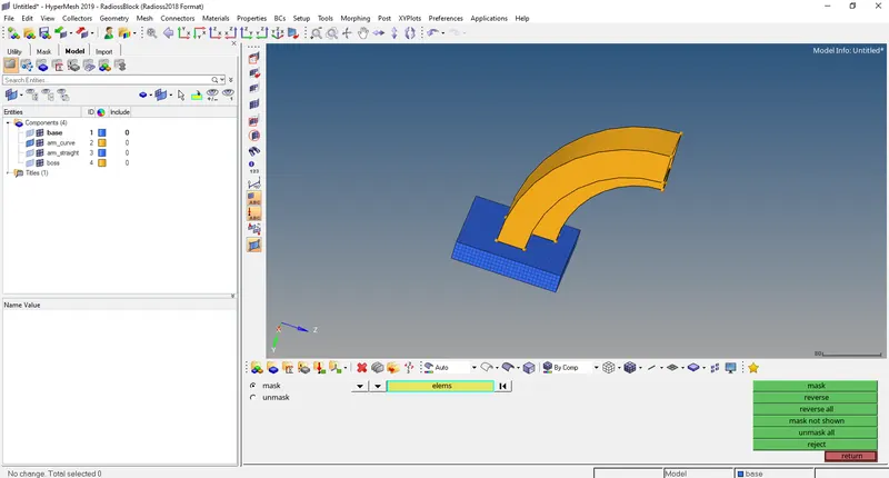
- Now we have to mask all the hex8 elements of the base using (Tools>mask>elems(by config-hex8)>mask) and unhide the arm_curve
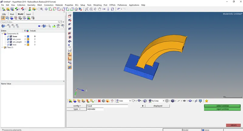
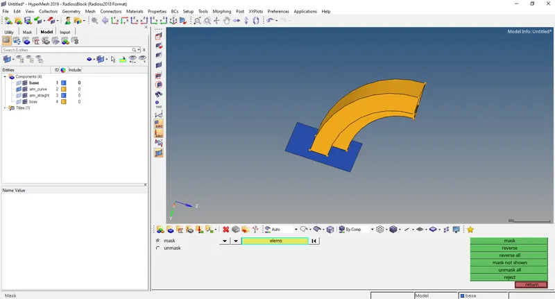
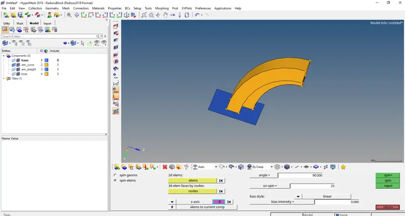
- Now to 3D mesh the arm_curve go to (3D>Spin>spin elems>spin-)
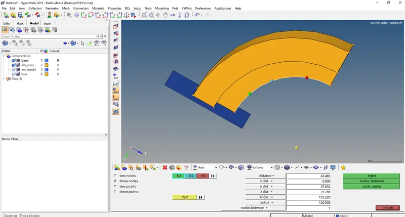
- But before that we need centre of the curve to get that go to (Geom>Distance>three nodes>circle center). Select any three nodes on the curve for N1, N2 and N3 and the click on circle center.
- Now go back to (3D>Spin>spin elems>spin-) and select the elements shown in the picture and select curve center as the base node.
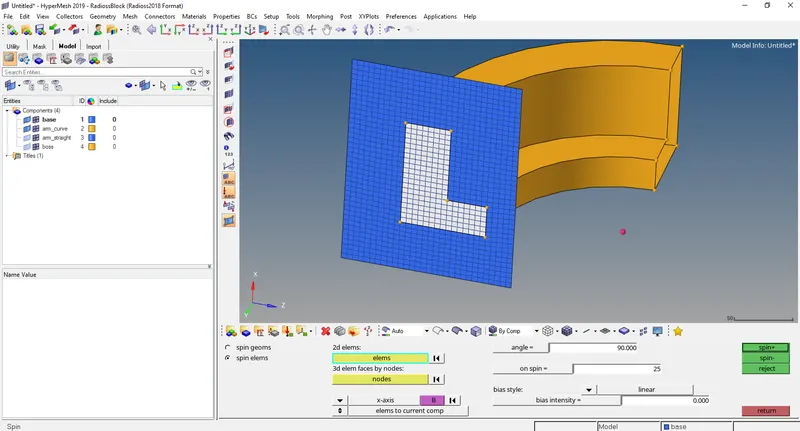
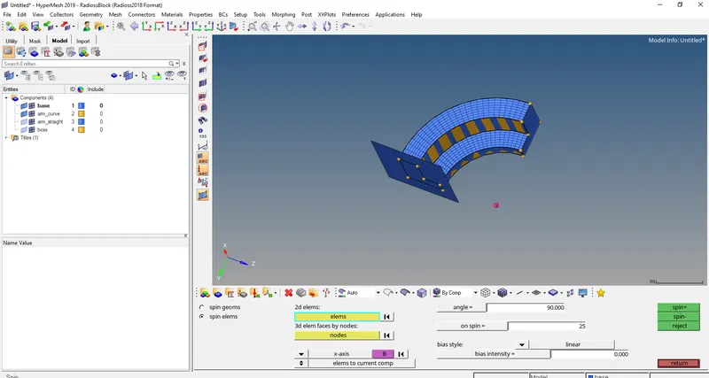
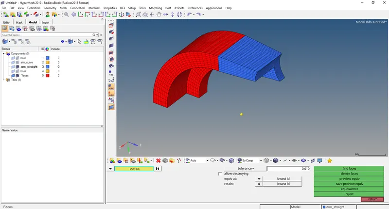
- Now we need to generate faces of the arm_curve to do that go to Tools>faces>arm_curve>find faces
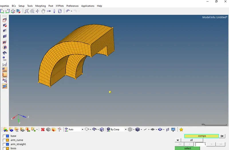
- Now we have to 2D mesh of front face of the arm_straight using (2D>automesh) and make sure the no. of elements matches correctly with the front face of the arm_curve.
- Now to 3D mesh this go to (3D>linear solid) for ‘from’ the elements of the arm_curve are selected and for ‘to’ the elements of the arm_straight are selected and sure the node orientation matches correctly.
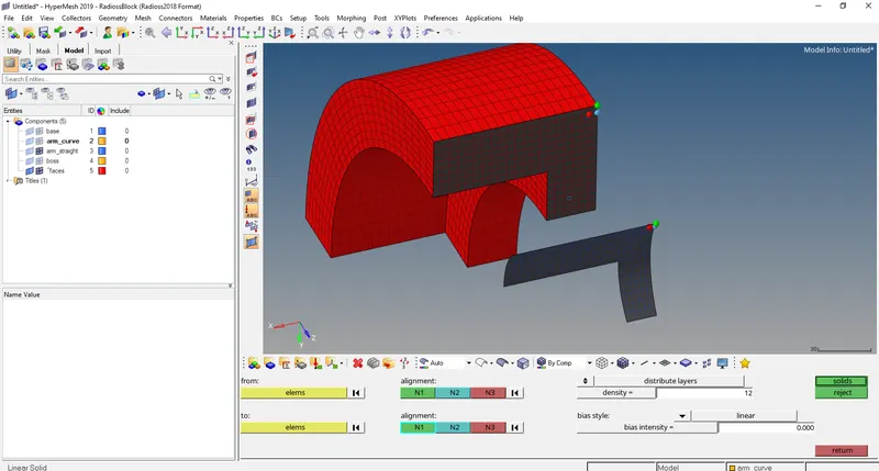
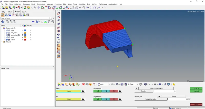
- Now we delete the faces (Tools>faces>delete face)
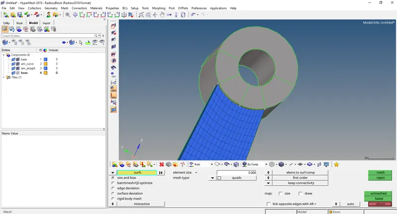
- Now we have to 2D mesh the boss face (2D>automesh)
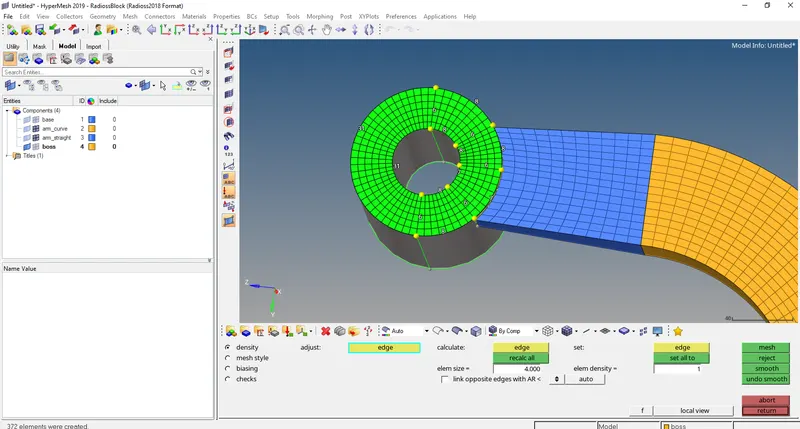
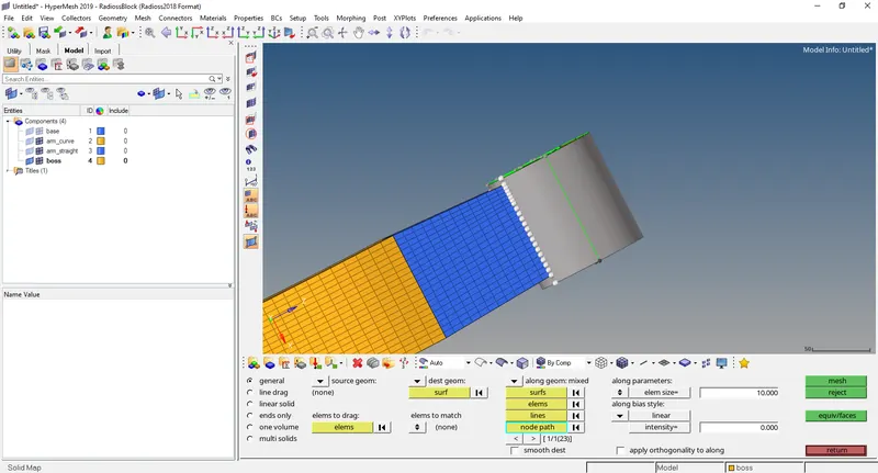
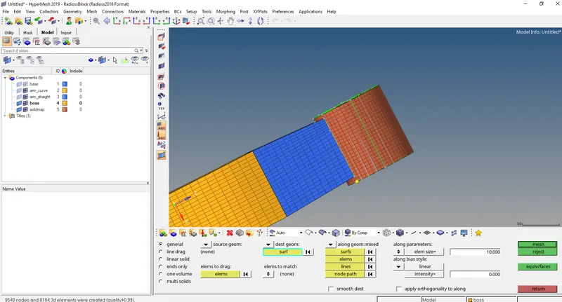
- Now we have to 3D mesh the boss using (3D>line drag>general>mesh).Select the opposite face of boss as destination surface and select correctly the node path and line for along vector option.
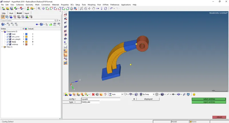
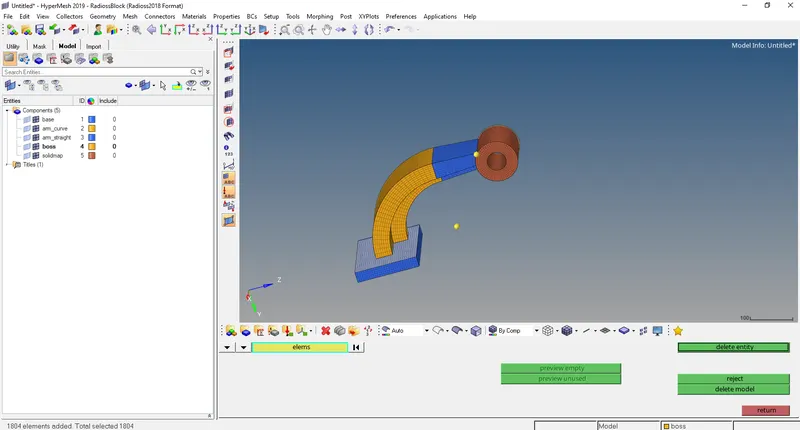
- Now delete all the quad elements using (Delete>elems(by config-quad 4)>delete)
Conclusion:- The project was completed successfully.