TRANSIENT STATE ANALYSIS OF SLOSHING OF GEARBOX
TRANSIENT STATE ANALYSIS OF SLOSHING OF GEARBOX
Sloshing
Sloshing is the movement of liquid inside another physical system which is also undergoing motion. For examples include propellant slosh in spacecraft tanks and rockets (especially upper stages) and the free surface effect (cargo slosh) in ships and trucks transporting liquids (for example oil and gasoline). The liquid must have a free surface to slosh, where the dynamic of the liquid can change the system dynamics.
Good Effects of Sloshing
- In gearbox, lubricant sloshing provides better movement of lubricant for lubrication.
Bad Effects of Sloshing
- There is high hydrodynamic forces and this results in vibration.
- Propellant slosh can introduce uncertainty in spacecraft attitude (pointing) which is often called jitter. Similar phenomena can cause pogo oscillationand can result in structural failure of space vehicle.
- Sloshing in partially liquid filled tank vehicles causes liquid cargooscillations in the tank under steering and/or braking manoeuvres reduce the stability limit and controllability of the vehicle.
- Ships with partially filled liquid tanks, such as LNG carriers or FPSOs, are sensitive to sloshing in case they are exposed to waves. The effect of sloshing can have a pronounced effect on the ship motions, in particular roll in oblique seas.
Dynamic Mesh
The dynamic mesh model allows the boundaries of a cell zone to move relative to other boundaries of the zone, and to adjust the mesh accordingly. The boundaries can move in linear, rotational motion or can be deformed.
Examples of dynamic mesh are ships moving on water, pistons moving inside an engine cylinder or a flap deflecting on an aircraft wing, or deforming, such as the elastic wall of a balloon during inflation, swinging of limb, flexible artery wall responding to the pressure pulse from the heart.
Advantages of Dynamic Meshing:
- It is used when boundaries move relative to each other.
- Dynamic mesh can be used there deformation.
- It has different methods which can be used for 2D or 3D model specifically or both.
- It has different methods which can be used for different element types.
Disadvantages of Dynamic Meshing:
- It is an expensive and time consuming process.
- To use this command effectively and quickly a higher processor system is required.
User-defined function (UDF)
A user-defined function, or UDF, is a function that you program that can be dynamically loaded with the ANSYS FLUENT solver to enhance the standard features of the code. UDFs are implemented in FLUENT code as macros. The general format for a defined macros is the macro name that is define followed by a underscore with the UDF name in parenthesis followed by a coma and then mentioning the variables that are to be passed.
UDF are used for following:
- Customize boundary conditions
- Material property definitions
- Adjust computed values on a once-per-iteration basis
- Initialize with a previous solution
- Execute at the end of an iteration
- Upon exit from ANSYS FLUENT
- Enhance post-processing
- Enhance existing ANSYS FLUENT models (such as discrete phase model, multiphase mixture model, discrete ordinates radiation model)
‘Dynamic mesh failed’ error
Dynamic mesh failed happens when wrong dynamic mesh method is selected. To get rid of this error the correct method for dynamic mesh needs to be selected based on type of model, type of mesh element.
‘Negative cell volume detected’ error
The negative cell volume error is shown when the mesh has been updated in a way to cause a negative cell volume (non-physical). This happens because of significant mesh motion (relative to cell size) per step. These factors are related and you could try to reduce the time step to avoid major mesh displacements.
Objective: To perform transient state analysis of 2D model of Gearbox.
Model
The 3D model was imported in Spaceclaim. The model consists of housing and two spur gears.
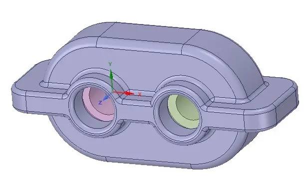
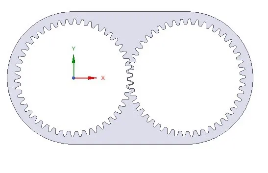
The volume is extracted and the 2D model of the gearbox is created for analysis.
Mesh
The model was meshed using ANSYS mesher with element size of 2 mm and the triangular element as method.
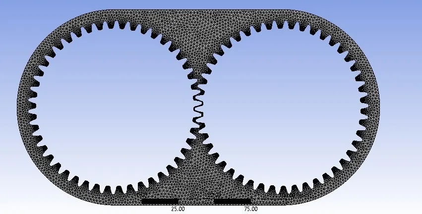
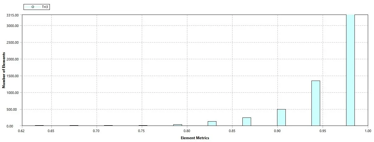
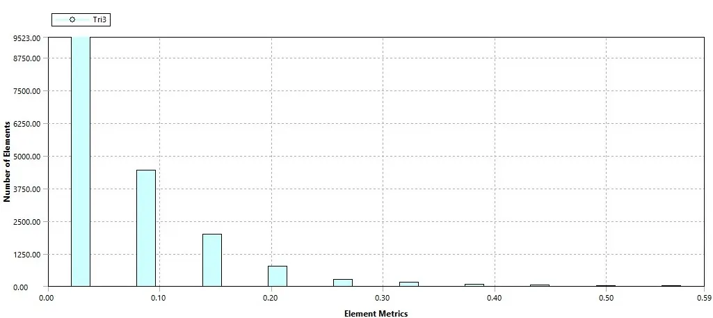
A mesh metric that identifies elements according to their quality was employed and it can be seen that the elements of lowest quality are minimal. Most of the elements have very high quality in the range of 0.85-1. Hence, the mesh is of acceptable quality. The meshed model is shown in image below. Number of Elements=17089, Nodes=10011.
The skewness of the elements is between 0-0.25 which is the accepted range.
SETUP
Fluid used are Engine Oil an n-heptane liquid.
|
Engine Oil |
n-heptane liquid |
|
|
Density (kg/m3) |
889 |
684 |
|
Viscocity (kg/m-s) |
1.06 |
0.000409 |
Engine Oil
Engine oil is any of various substances comprising base oils enhanced with various additives, particularly antiwear additive in addition to detergents, dispersants and, for multi-grade oils, viscosity index improvers. It is used for lubrication of internal combustion engines. The main function of motor oil is to reduce friction and wear on moving parts and to clean the engine from sludge (one of the functions of dispersants) and varnish (detergents). It also neutralizes acids that originate from fuel and from oxidation of the lubricant (detergents), improves sealing of piston rings, and cools the engine by carrying heat away from moving parts.
n-heptane liquid
Heptane is an alkane of seven carbon atoms, with the chemical formula C7H16. The term commonly refers to n-Heptane, the straight-chain isomer, but may refer to any of the nine structural isomers with that formula, or to a mixture of them.
n-Heptane is one of the components of gasoline (petrol). When used as a test fuel component in anti-knock test engines, a 100% heptane fuel is the zero point of the octane rating scale (the 100 point is 100% iso-octane).
User-defined function
The code is written in C++
#include "udf.h"
DEFINE_CG_MOTION(right_motion, dt, vel, omega, time, dtime)
{
vel[0] = 0.0;
vel[1] = 0.0;
vel[2] = 0.0;
omega[0] = 0.0;
omega[1] = 0.0;
omega[2] = 2.0e2; /* [rad/s]*/
}
DEFINE_CG_MOTION(left_motion, dt, vel, omega, time, dtime)
{
vel[0] = 0.0;
vel[1] = 0.0;
vel[2] = 0.0;
omega[0] = 0.0;
omega[1] = 0.0;
omega[2] = -2.0e2; /* [rad/s]*/
}
Calculations
Here, Angular Velocity (ω) = 200 rad/s,
ω= `(2πN)/60`
N= `(200*60)/2π` = 1910.828 rpm= 31.847 rps
For 1 rotation of gear,
1 ÷ 31.847 = 0.031407 seconds.
Case 1:
A TRANSIENT STATE ANALYSIS of 2D model of gearbox is done using ANSYS FLUENT to observe flow pattern of fluid inside of gearbox. Fluid used is Engine oil with 20% immersion inside the gearbox.
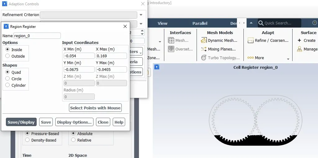
Marked Region
Marked region for 20% immersion of Engine oil.
Residual
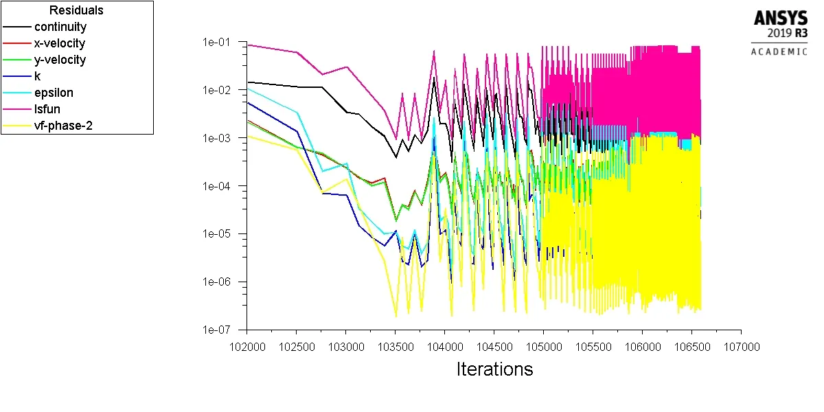
Time step= 9000 and time step size= 5e-06 were ran. The residual plot is plotted in ANSYS FLUENT shown below.
Result
Volume fraction Contour
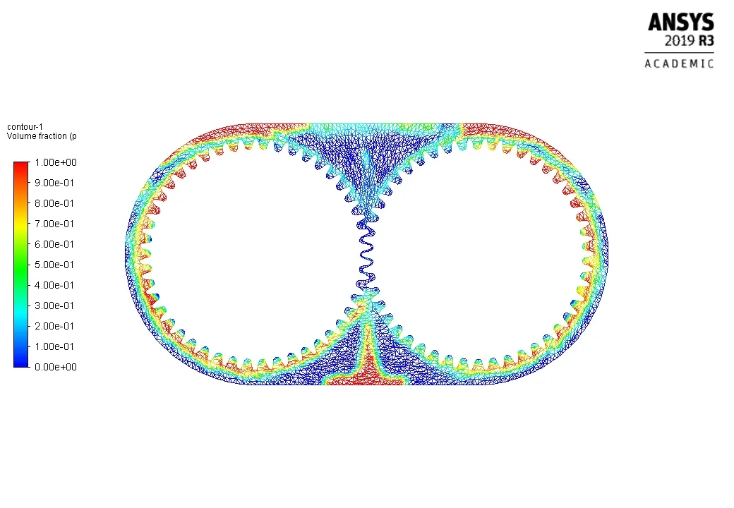
Flow time Calculated:
Flow time = 0.0449999999999989 sec,
Time for 1 rotation of gear= 0.031407 sec.
So, Flow time = 0.0449999999999989 seconds is for 1.433 rotation of gear.
Case 2:
A TRANSIENT STATE ANALYSIS of 2D model of gearbox is done using ANSYS FLUENT to observe flow pattern of fluid inside of gearbox. Fluid used is n-heptane liquid with 20% immersion inside the gearbox.
Marked Region
Marked region for 20% immersion of n-heptane liquid.
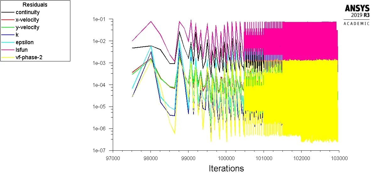
Residual
Time step= 9000 and time step size= 5e-06 were ran. The residual plot is plotted in ANSYS FLUENT shown below.
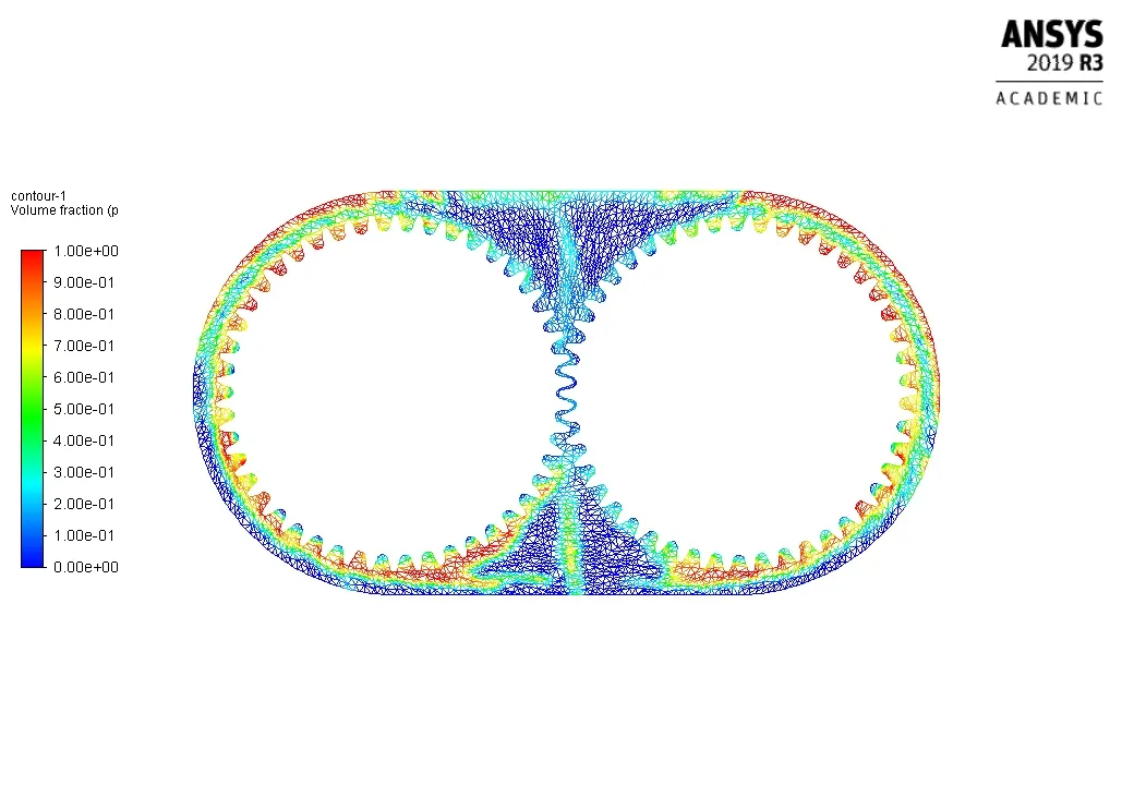
Result
Volume fraction Contour
Flow time Calculated:
Flow time = 0.0449999999999989 sec,
Time for 1 rotation of gear= 0.031407 sec.
So, Flow time = 0.0449999999999989 seconds is for 1.433 rotation of gear.
Case 3:
A TRANSIENT STATE ANALYSIS of 2D model of gearbox is done using ANSYS FLUENT to observe flow pattern of fluid inside of gearbox. Fluid used is Engine Oil with 30% immersion inside the gearbox.
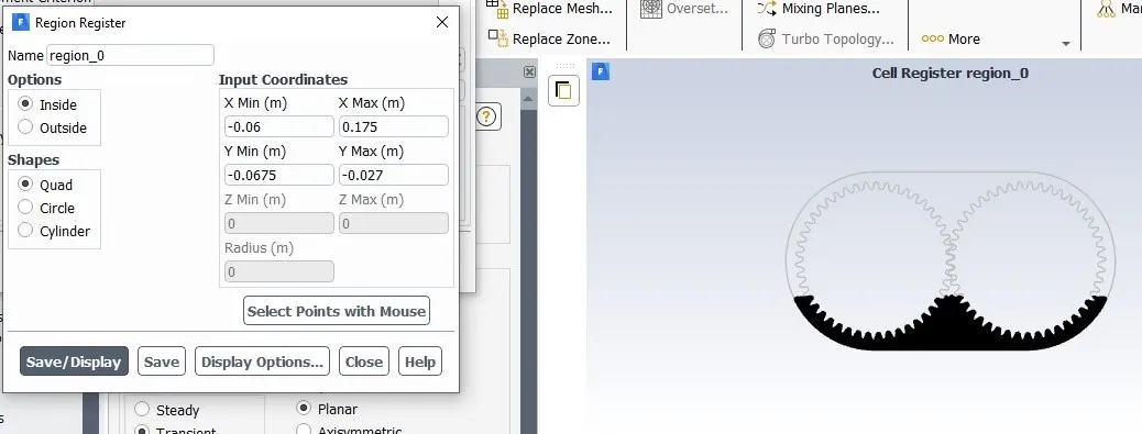
Marked Region
Marked region for 30% immersion of Engine oil.
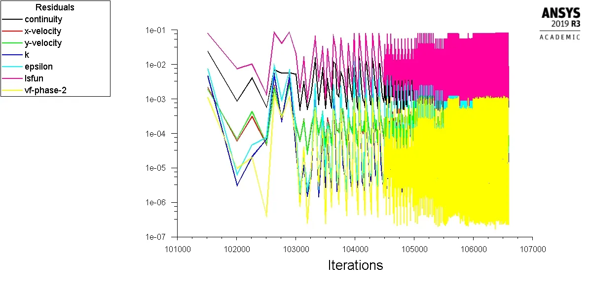
Residual
Time step= 9000 and time step size= 5e-06 were ran. The residual plot is plotted in ANSYS FLUENT shown below.
Result
Volume fraction Contour
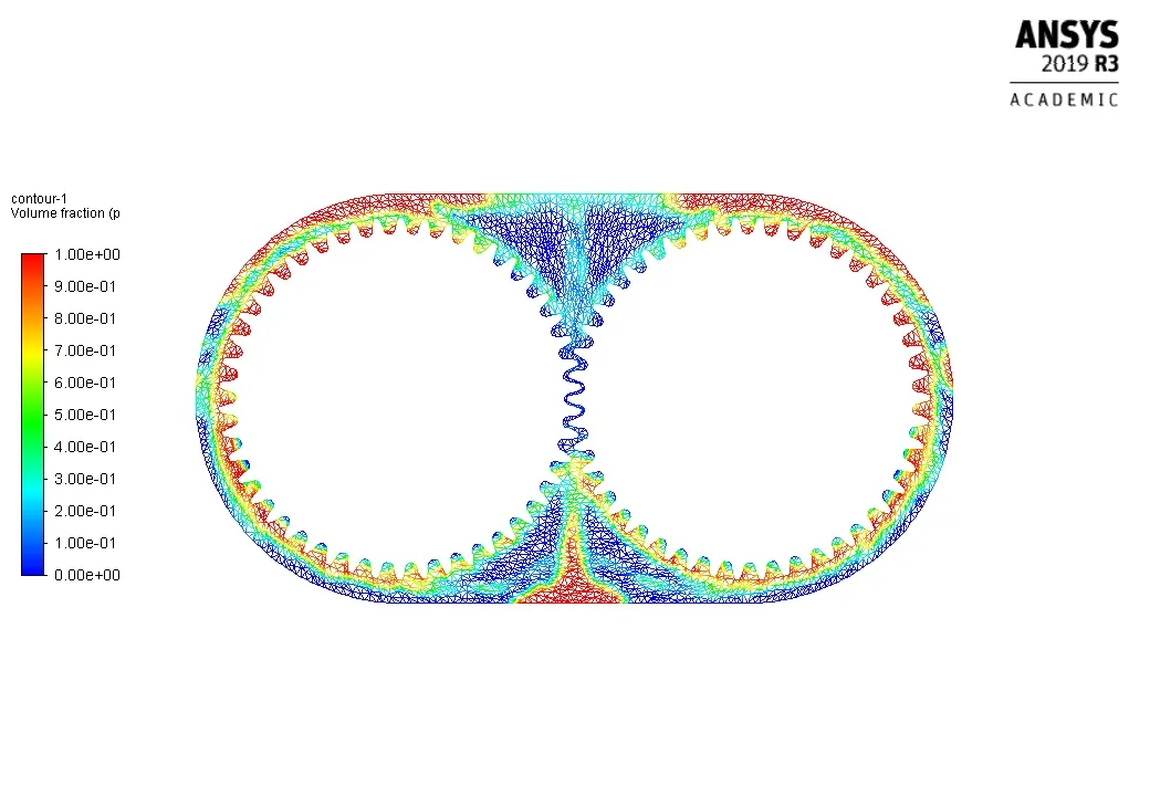
Flow time Calculated:
Flow time = 0.0449999999999989 sec,
Time for 1 rotation of gear= 0.031407 sec.
So, Flow time = 0.0449999999999989 seconds is for 1.433 rotation of gear.
Case 4:
A TRANSIENT STATE ANALYSIS of 2D model of gearbox is done using ANSYS FLUENT to observe flow pattern of fluid inside of gearbox. Fluid used is n-heptane liquid with 30% immersion inside the gearbox.
Marked Region
Marked region for 30% immersion of n-heptane liquid.
Residual
Time step= 9000 and time step size= 5e-06 were ran. The residual plot is plotted in ANSYS FLUENT shown below.
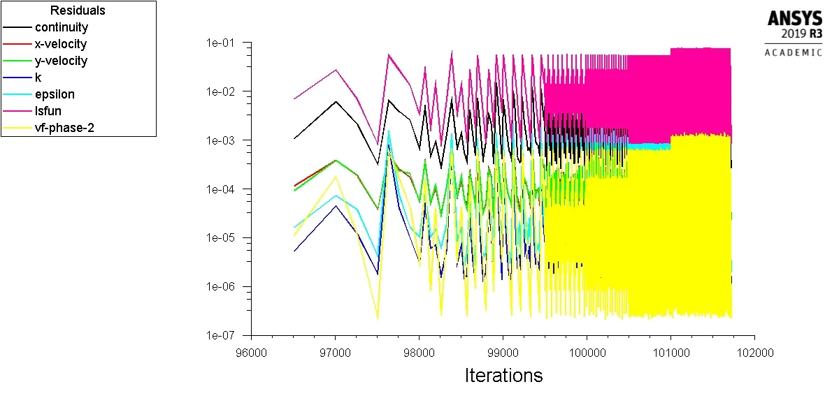
Result
Volume fraction Contour
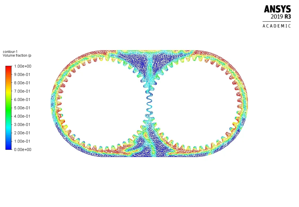
Flow time Calculated:
Flow time = 0.0449999999999989 sec,
Time for 1 rotation of gear= 0.031407 sec.
So, Flow time = 0.0449999999999989 seconds is for 1.433 rotation of gear.
Conclusion
- n-heptane is less viscous than engine oil so has more sloshing effect than engine oil.
- 20% immersion has more sloshing effect than 30% because of more free surface available.