Week 9-Creation of 1D Connectors Challenge
CREATION OF 1D CONNECTORS
OBJECTIVE: To create 1D connectors on the given model.
INTRODUCTION:
-Connectors can be 1D, 2D and 3D. Connectors are used to connect two or components. Geometric entities that define connections between other entities. Connectors are of different types such as welding, bolts, adhesives, etc.
-To create connectors the components are linked through Nodes – created at the node location, Points – created at the point location, Lines – created for the line, line may be split into multiple projection locations as specified by the offset, spacing, and density values, Elements – created at the element location (adhesives only), Surface – created at the surface location (adhesives only).
-Connector Realization – The creation of the finite element representation of that connector.
-Connector State – Whether an FE representation of a connector has been created
- Unrealized - The initial status of the connector entity upon creation
- Realized - The status only if creation of the FE weld representation at the connector was successful.
- Failed – The status if the creating the FE weld representation at the connector was not successful.
CAD MODEL:-
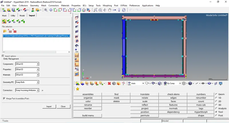
The model is imported in hypermesh using option of import model in tab bar.
QUALITY CRITERIA
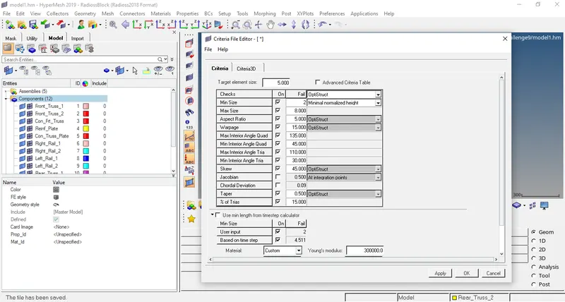
Target element size = 5 mm.
|
Aspect ratio |
5 |
|
Skewness |
45 |
|
Warping |
15 |
|
Taper |
0.5 |
|
Min. length |
2 |
|
Max. length |
8 |
|
Min. quad angle |
45 |
|
Max. quad angle |
135 |
|
Min. tria angle |
30 |
|
Max. tria angle |
110 |
|
% tria |
15 |
CONNECTORS
-Required type of connector that need to be connected for the given component are
- Right_rail_2 and Front_Truss_1:- Seam-quad (angled+capped+L)
- Left_rail_2 and Front_Truss_1:- Quad elements
- Front_truss_1, Front_truss_2 and Right_rail_1:- Spot weld with 3 layers and 5 mm diameter
- Front_truss_1, Front_truss_2 and Left_rail_1:- Hexa (adhesives)
- Rear_truss_2 and Right_rail_2:- Bolt connector
- Rear_truss_2 and Left_rail_2:- Bolt connector
- Right_rail_1 and Right_rail_2:- Spot weld with rigid elements
- Left_rail_1 and Left_rail_2:- Spot weld with spring elements
PROCEDURE:-
MODEL1
- First the frame assembly is imported using import model option in tab bar in Hypermesh.
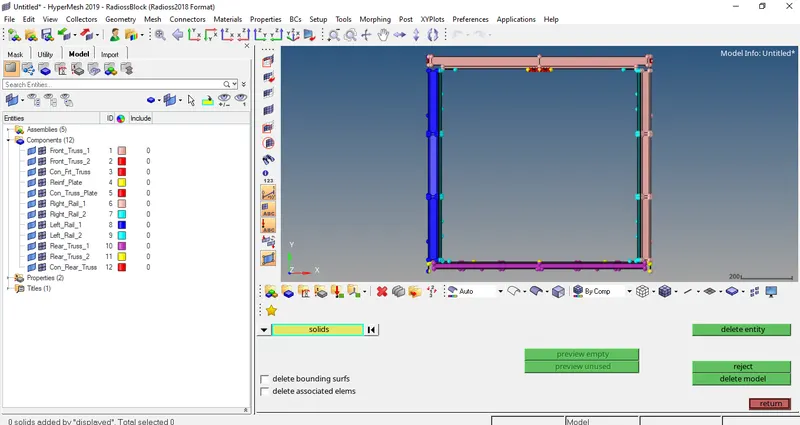
- Now we have to delete the solid part of the model.
- We have to set quality criteria in criteria preference option.
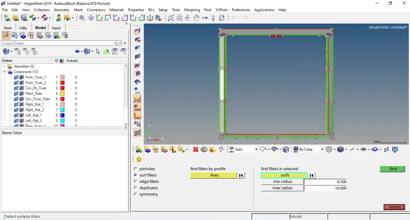
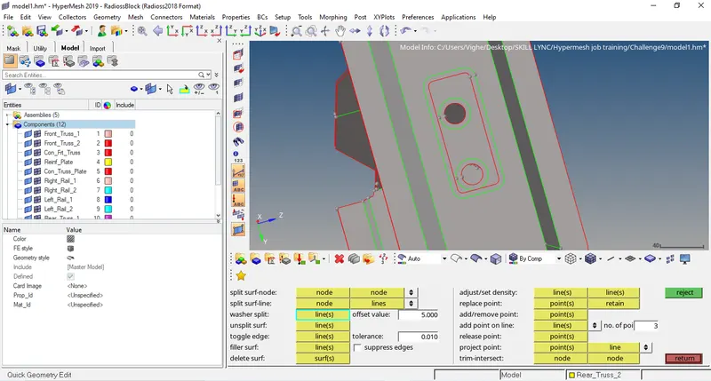
- We get rid of surface fillets using defeature option (Geom>Defeature>surfs fillets) also we have to do geometrical cleanup using quick edits options like add/replace points, toggle edge, split surfs etc (Geom>quick edits).
- The meshing of the model with target element= 5 mm and mesh type = quads is done (2D>automesh).
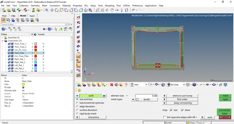
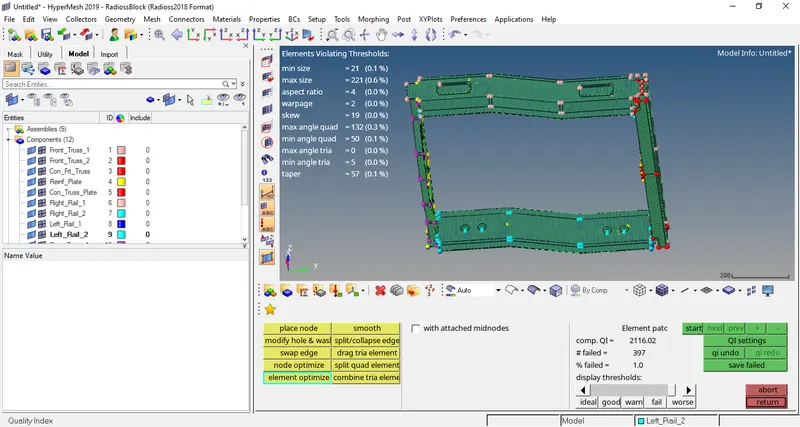
- The mesh created is not proper as the parts gets complex so the mesh needs to be improved.
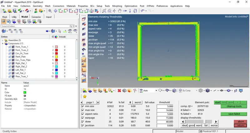
- To check the quality of meshing the quality criteria option is opened and the highlighted elements are improved using QI tools given till all the elements are unhighlighted. (2D>Quality Criteria).
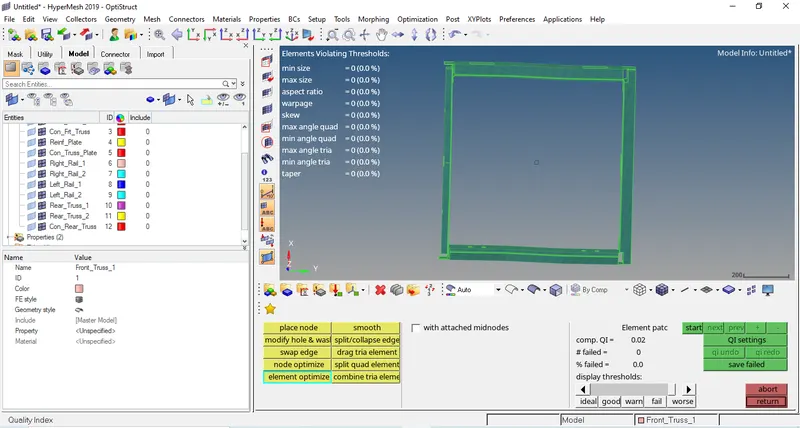
- Now we have to create connectors to connect as given accordingly.
- Right_rail_2 and Front_Truss_1:- Seam-quad (angled+capped+L). Go to 1D>Connectors>seam.
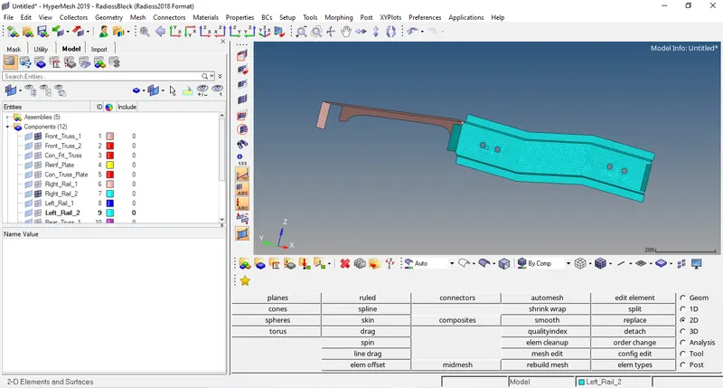
Now, select the nodes where we want to create connector.
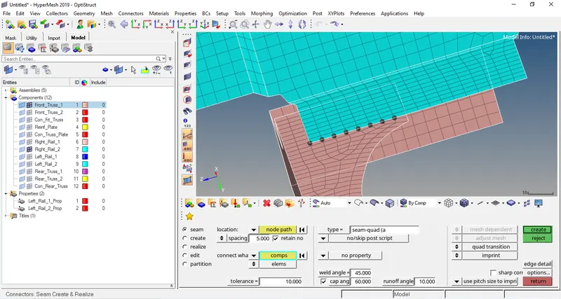
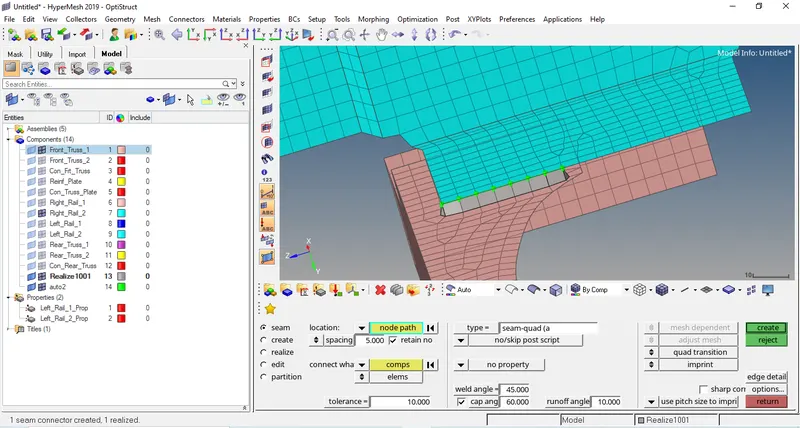
- Left_rail_2 and Front_Truss_1:- Quad elements. Go to 1D>connectors>seam.
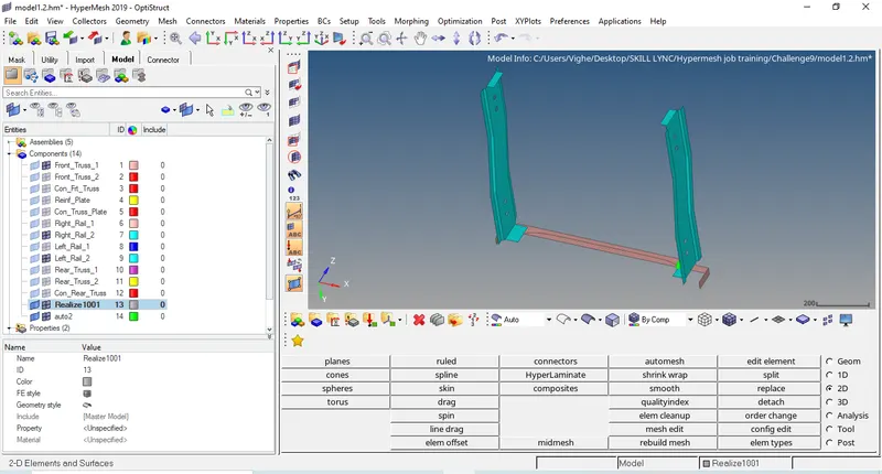
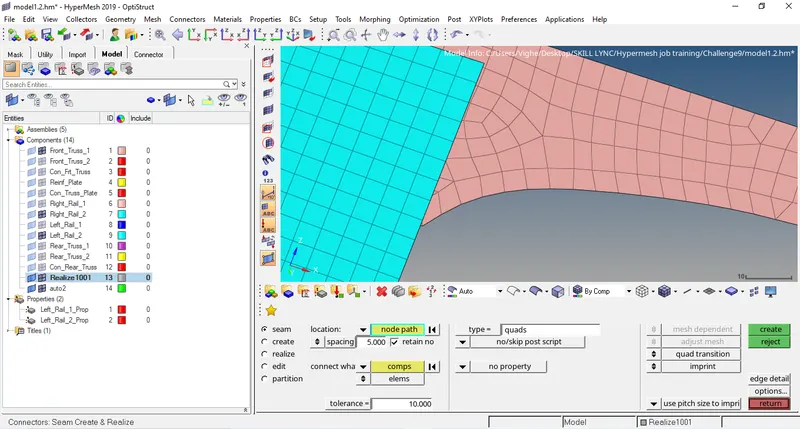
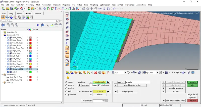
- Front_truss_1, Front_truss_2 and Right_rail_1:- Spot weld with 3 layers and 5 mm diameter
Go to 1D>connectors>spot
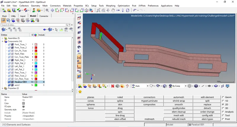
Now, select the nodes where we want to create connector.
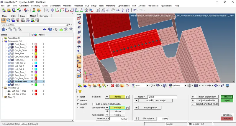
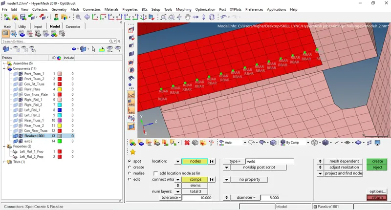
- Front_truss_1, Front_truss_2 and Left_rail_1:- Hexa (adhesives). Go to 1D>connectors>seam
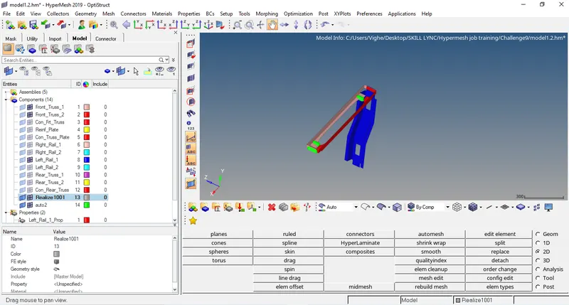
Now, select the nodes where we want to create connector & Front Truss 1 and Front Truss 2 are selected as components.
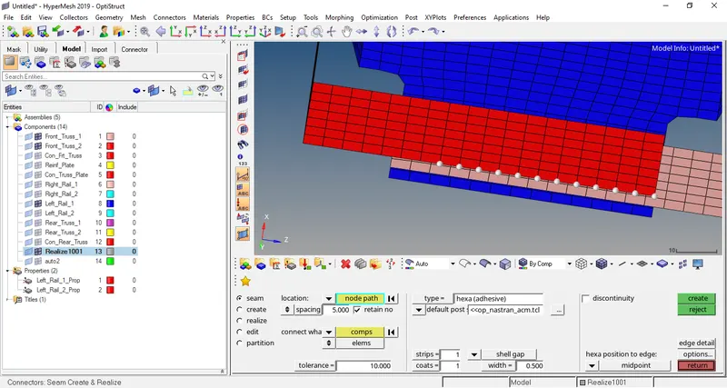
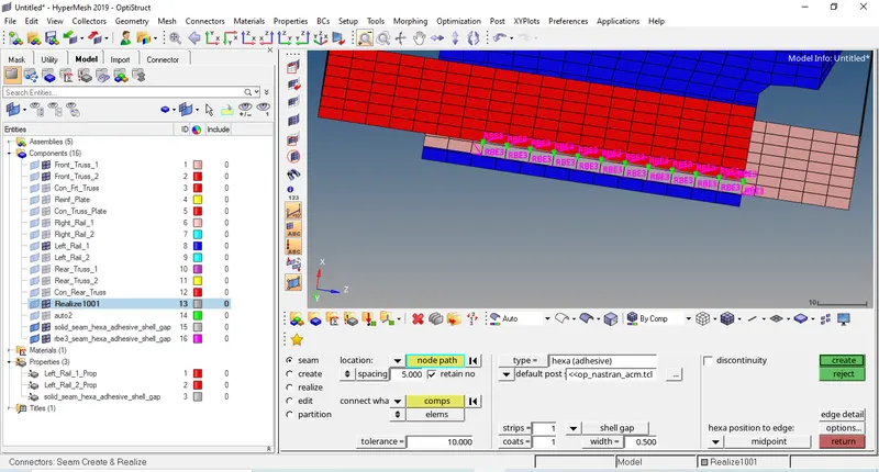
Now, select the nodes where we want to create connector & Front Truss 2 and Left rail 1 are selected as components.
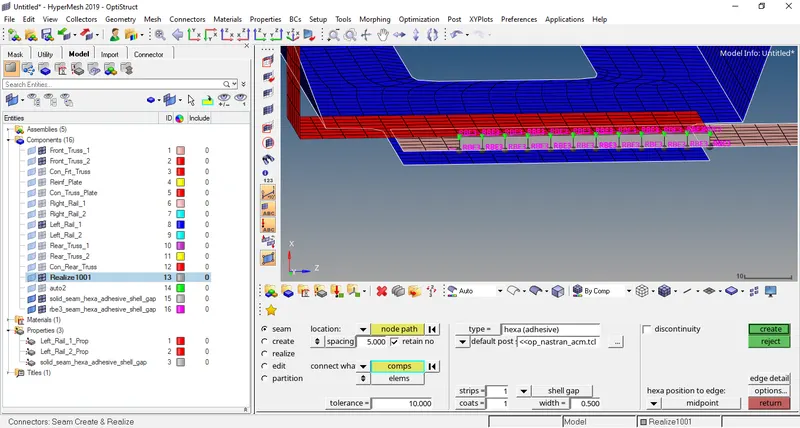
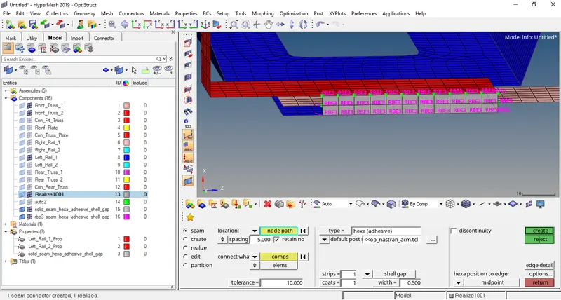
- Rear_truss_2 and Right_rail_2:- Bolt connector. 1D>Connectors>Bolt
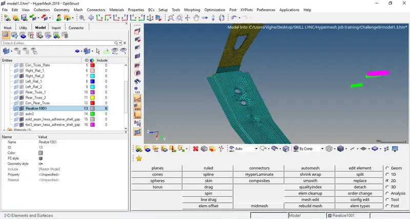
Now, select the nodes where we want to create connector.
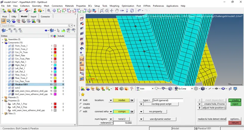
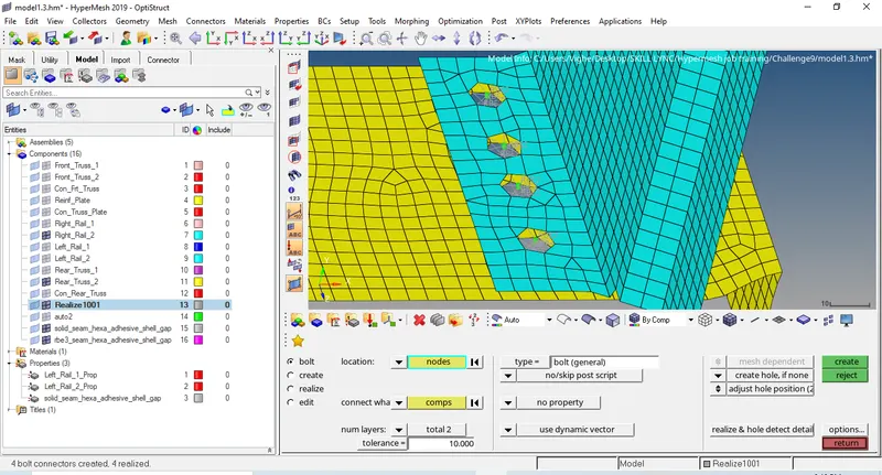
- Rear_truss_2 and Left_rail_2:- Bolt connector
Go to 1D>connectors>Bolt
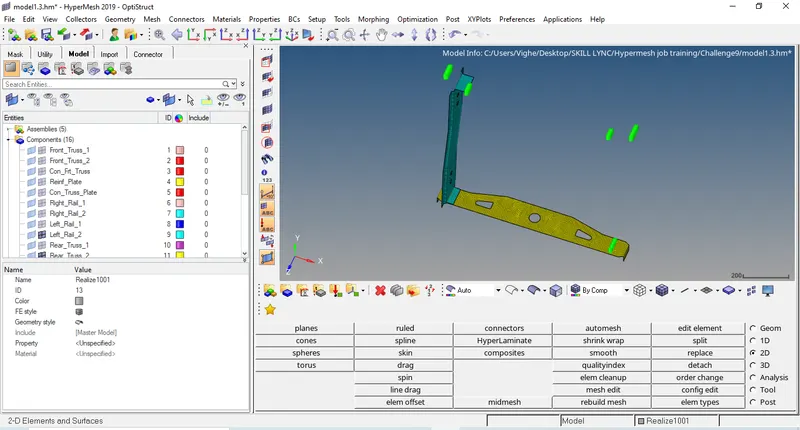
Now, select the nodes where we want to create connector.
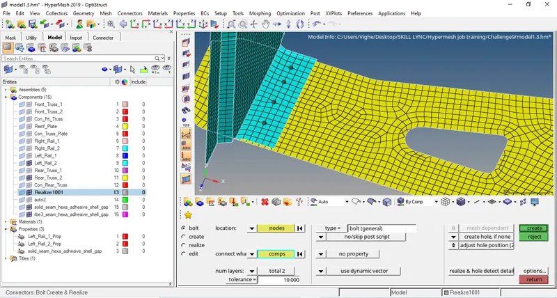
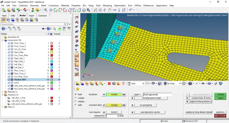
- Right_rail_1 and Right_rail_2:- Spot weld with rigid elements. Go to 2D>connectors>spot
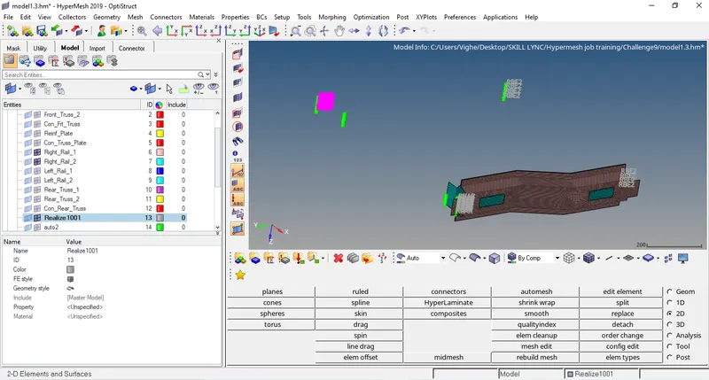
Now, select the nodes where we want to create connector.
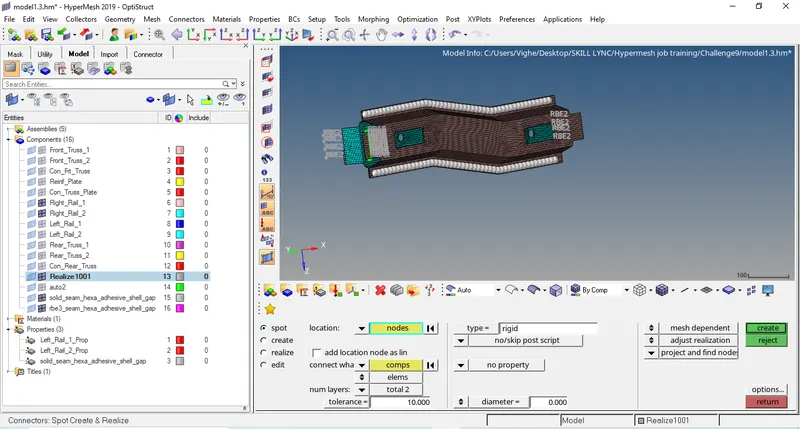
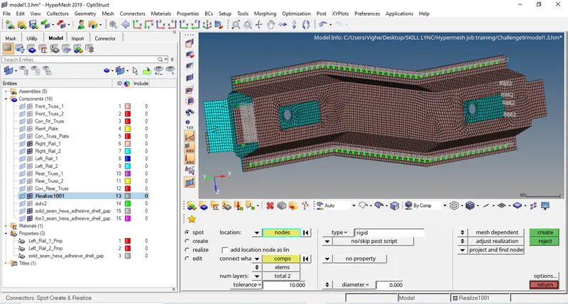
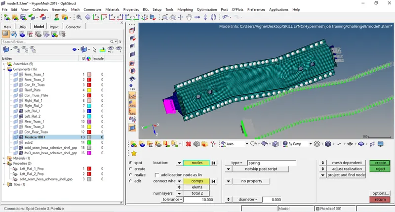
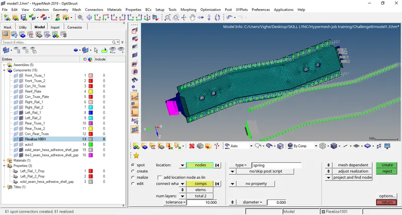
- Left_rail_1 and Left_rail_2:- Spot weld with spring elements. Go to 2D>connectors>spot
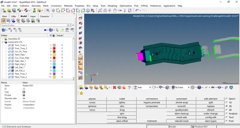
Now, select the nodes where we want to create connector.
- OTHERS
Front truss1 and reinf plate:- Spot weld rigid. Go to 1D>connectors>spot
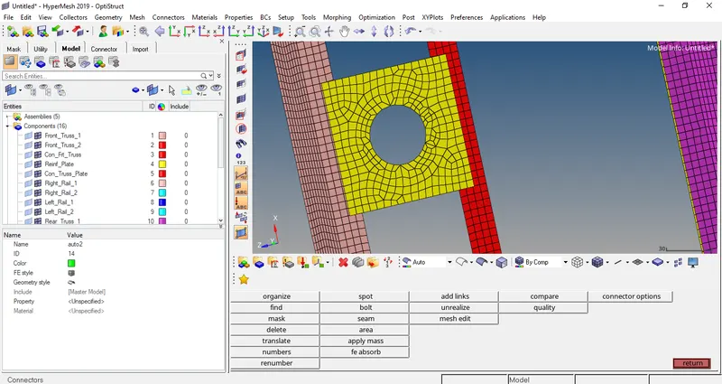
Now, select the nodes where we want to create connector.
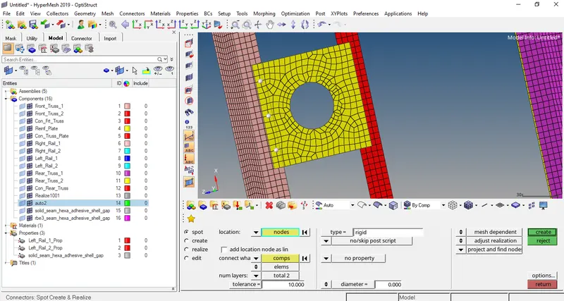
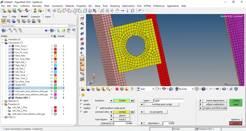
- Front truss2 and reinf plate- Spot rigid. Go to 1D>connectors>spot
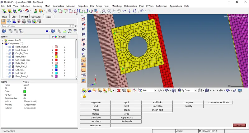
Now, select the nodes where we want to create connector.
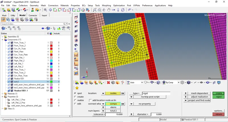
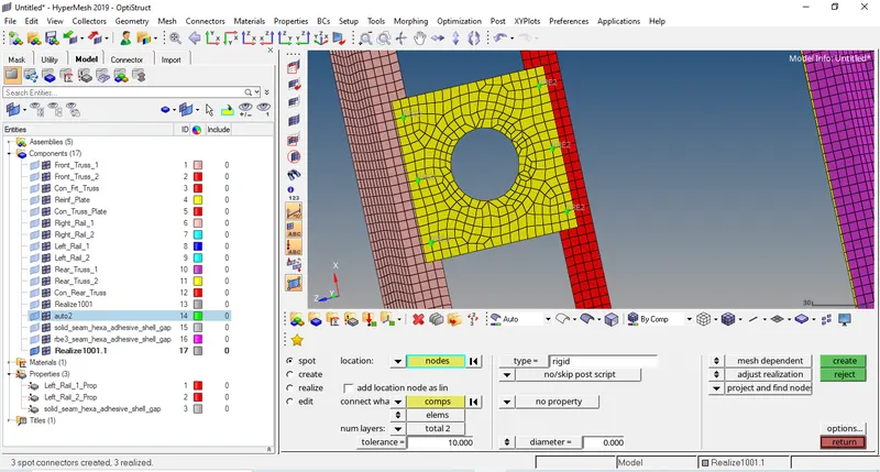
- Front truss 2 and right rail 2- Seam quad (angled+capped+L). Go to 1D>connectors>seam
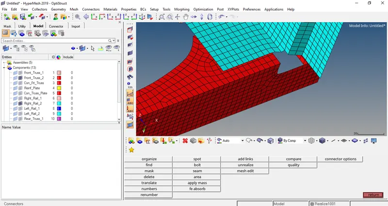
Now, select the nodes where we want to create connector.
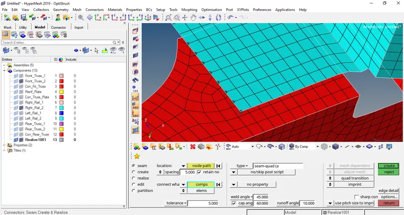
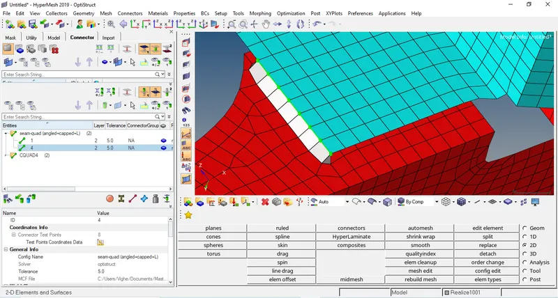
- Front truss 2 and left rail 2- Quad. Go to 1D>connectors>seam
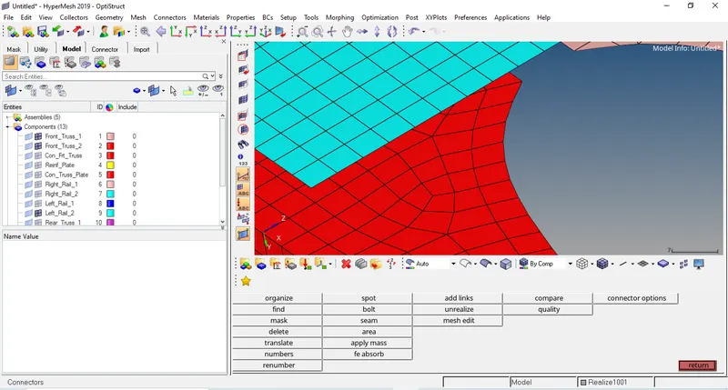
Now, select the nodes where we want to create connector.
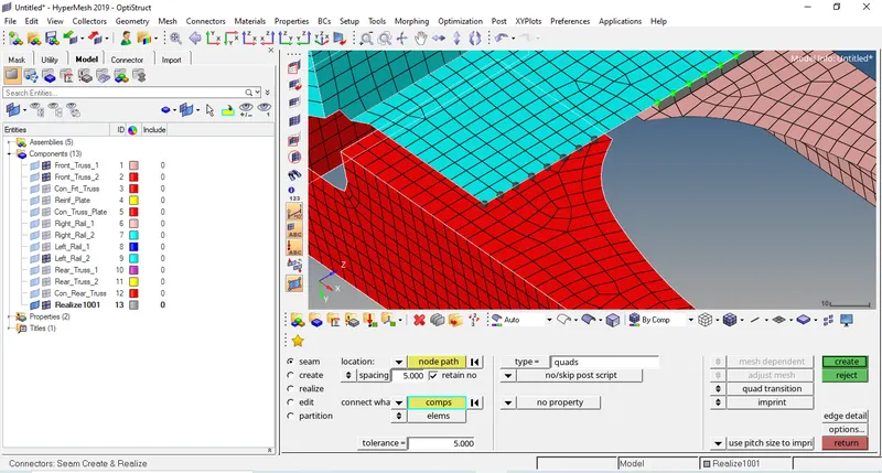
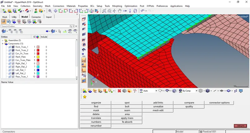
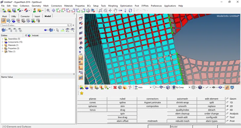
- Now we have to check whether any duplicate elements exists. Go to Shrink elements to see duplicate elements.
- Complete model with all the required connectors.
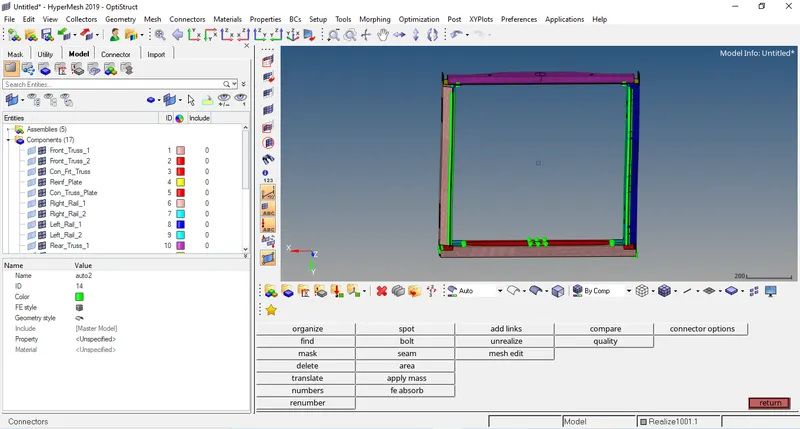
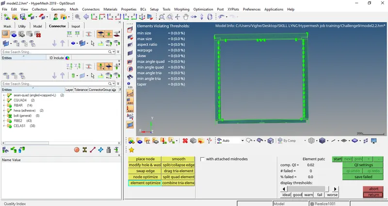
- Now lets check the quality of mesh after creation of connectors. If any elements are not proper we can optimise using element cleanup. (2D>quality criteria).
CONCLUSION: The 3D tetra mesh was created successfully.