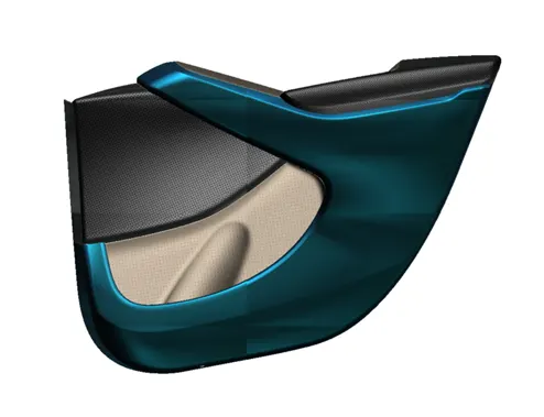
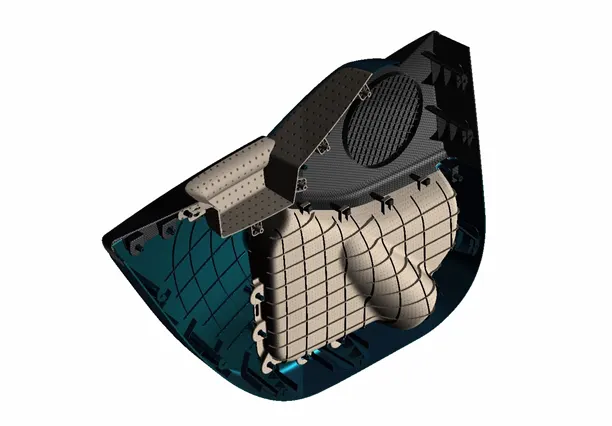
Door Trim Model
OBJECTIVE:-
Class A Surface Was Received From The Styling Team. My Objective Is To develop the Class A Surface Received Into Manufacturable Product Design Following TheOEM Design Standards Using CATIA V5 Surface Workbench.
SUMMARY:-
The Project Report explain in brief the Design life cycle followed in the automotive industry While Developing Plastic Trims For Cars Door From a Class A Surface Provided. Using, CATIA V5 Surface Workbench. It Explains The Method I Followed For CreatingThe Main Tooling Axes, Side Core Axes, Class B Surface, Class C Surface And FinalClosed Body Creations. It Also Explains The Draft Analysis Performed To Check The Manufacturability Of The Products Using Injection Moulding. Various Plastic DoorTrims Such As Map Pockets, Armrest, Lower Substrate Etc With Attachment FeaturesWere Successfully Developed In This Project. The Design Should Be Done In Such a Way That, It Is Manufacturable In a CostEfficient Manner. Here The Door Interior Plastic Trims Were Designed By Following The Injection Moulding Principles.
PROCEDURE
Class A Surface
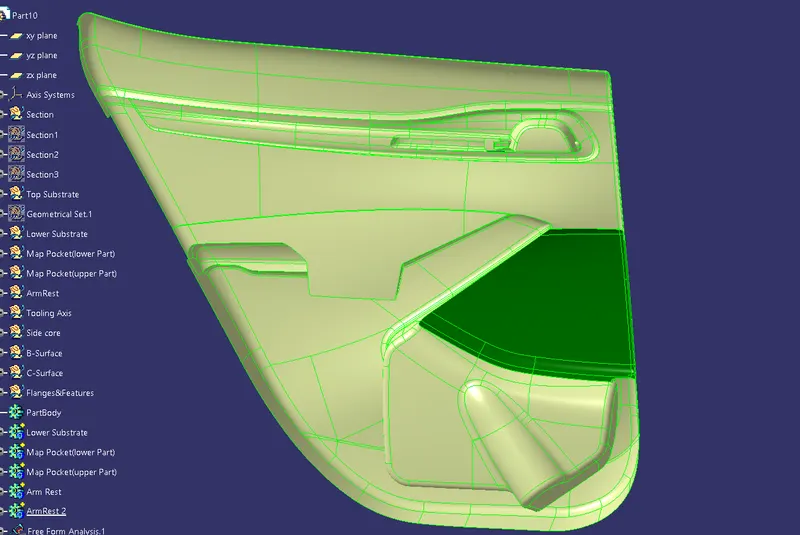
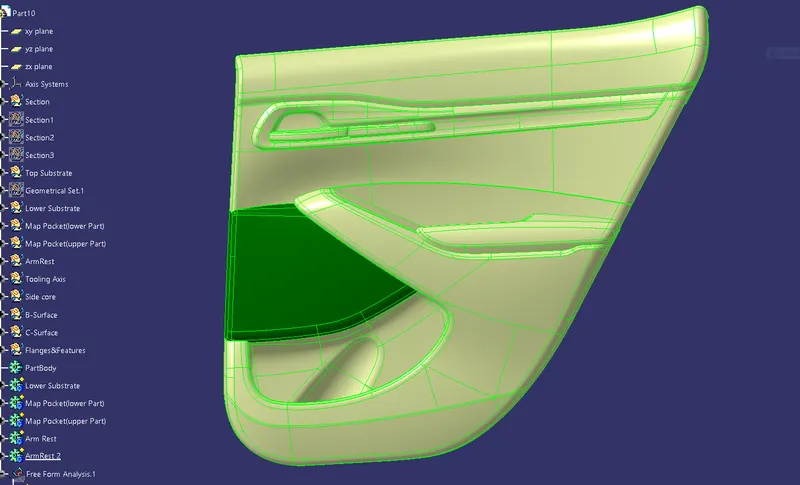
In Automotive Industry There Will Be a Dedicated Team Who Will Perform The Aesthetic Designing Of Various Components Including The Whole Vehicle. They Will Create Various Concept Sketches After Ideation. After That, They Will also create a Class A Surface Of The Product. This Class A Surface Is Then Passed OverTo The NPD CAD Team. They Will Initially Inspect The Class A Surface In Order To Check If The Design Is Manufacturable Or If It Is Following The Engineering Principles. If There Are Any Issues About The Design, They Will Contact The Product Design Team And Will Ask To Modify The Class A Surface In Order To Solve The Problem. Here I Received The Class A Surface and Master Section As Shown Below.
Plastic Parts:
- Map Pocket( Upper Part )
- Map Pocket( Lower Part)
- Armrest
- Lower Substrate
Map Pocket (Upper Part)
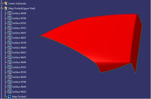
Here I extracted the class A surface of Map Pocket from input as shown below.
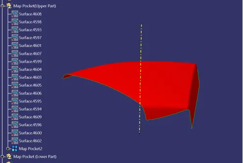
Next, main tooling axis was created by applying a zero distance value on the surface as shown below.
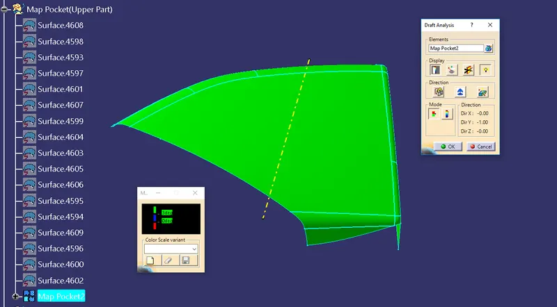
Next, the surface was inspected using draft analysis as shown below. In industry, if there is an issue with the surface after inspection, engineers must discuss the issue with the aesthetic design team who provide class A for troubleshooting the issue.
-Class B surface development
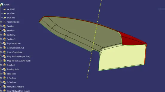
Class B surface was created from the class A surface using the 'Extract/Multiple Extract' and offset option. Major surfaces of Class A surface was offset at a distance of 2.5 mm thickness.
Class C surface development
-Class C surface was swept along the boundary of Class A using the ' Sweep' option at an angle of 3 degrees outwards with respect to tooling direction.
-Then, the class-A surface of the map pocket and the Class C surface were joined together as shown below.
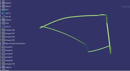
C surface
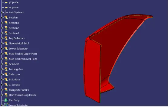
Class A & C join
-After joining class A and C surfaces, It was trimmed together with the class B surface in order to form the closed surface as shown below.
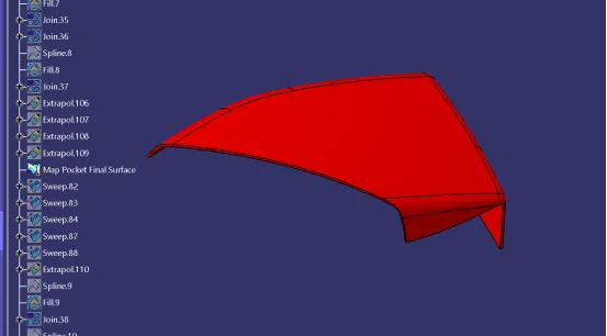
Final closed surface
-A part body was Formed using the closed surface. The next step was the creation of mounting features for fixing the component. the flange is created to Fixed the position of the Lower Substrate with the help of heat stakes. the Hole cutout is provided for heat stake. And also I have created the Extra Feature on the surface like Speaker.
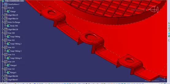
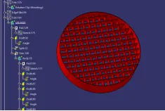
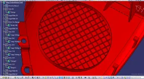
Speaker
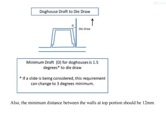
-The Dog House is Created for the mounting of the Retainer clip. The height of the dog house is more So, To Provide the strength to the dog house I had created the Ribs.
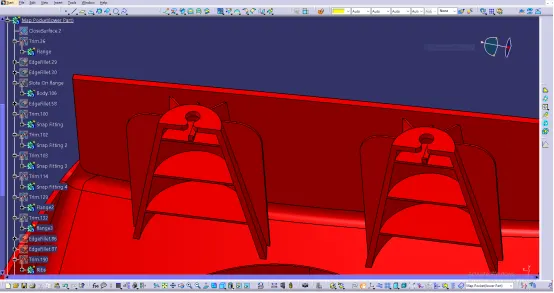
-Dog house is an engineering feature used in the plastic trim design. The primary function of a dog house is to avoid sink marks on the class A surface which may occur due to features such as a locator or rib on the backside of Class So the best possible solution is to increase the height and decrease the cross-sectional thickness of the ‘legs’ by using a dog house. We can also use them for solving the necessity of large length features such as Heat Stakes And Locators which may require large length sometimes.
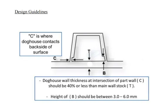
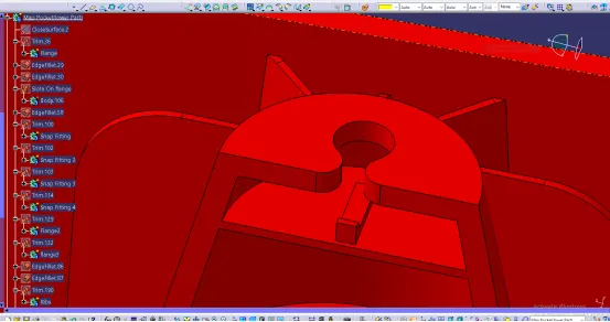
- A locking feature is created on the dog house to stop the movement of the Retainer Clip so that the Retainer clip does not come outside when it is mounted on the dog house.
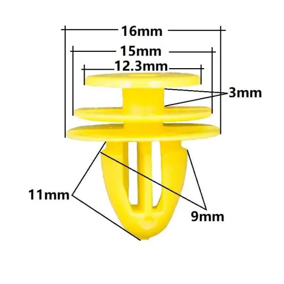
-Retainer Clip is Easy-To-Assemble with BIW Component And Remove Without Special Tools.
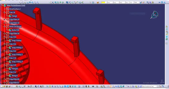
-Snap fitting Feature is also created on the surface to connect with the Map Pocket(Lower Part). Snap-fit is an assembly method used to attach flexible parts, usually plastic, to form the final product by pushing the parts' interlocking components together. There are a number of variations in snap-fits, including cantilever, torsional and annular.
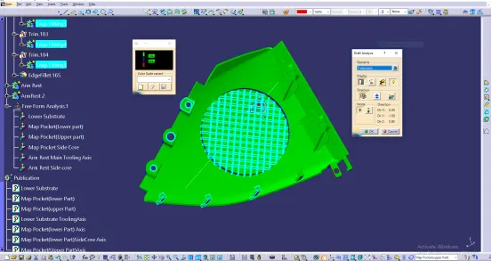
Draft Analysis of Map Pocket(Upper part)
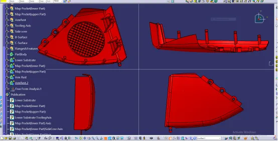
All Multiple Views of the Map Pocket (upper Part)
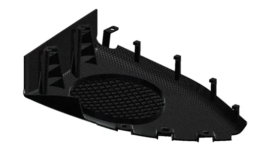
- Map pocket( Lower part)
The lower part of the map pocket was also created by following the same steps and procedures. Initially class A surface was extracted from the input surface as shown below.
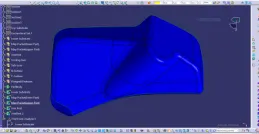
-Then, I performed the draft analysis. The walls were below 3 degrees (blue). If it is an industrial project, we must discuss it with the aesthetic design team in order to avoid this issue by modifying the surface. To clear the other side of the part I have provided the Side Core tooling axis.
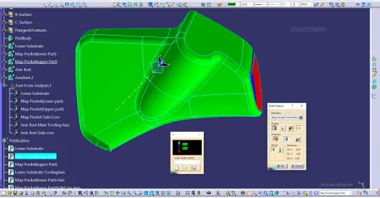
(Draft With Main tooling Axis)
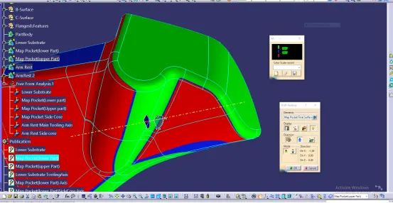
(Draft With Side Core tooling Axis)
-Then, as earlier, the class B surface was formed using class-A surface. The offset distance was 2.5 mm as it is the thickness of the component.
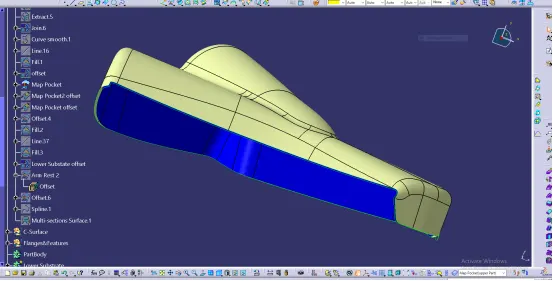
-Class C surface was swept along the boundary of Class A using the ' Sweep' option at an angle of 3 degrees outwards with respect to tooling direction.Finally, all the swept surfaces were trimmed and joined together With the A &B surface to Get the Final Surface.
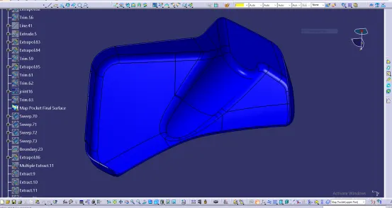
-Next step was the creation of mounting features for fixing the component on the lower substrate.Then, mounting features were created for fixing the component to the lower substrate. Actually, the mounting features were designed after modelling all the components and deciding the position of fixing points. Heat stakes were used to fix the components.
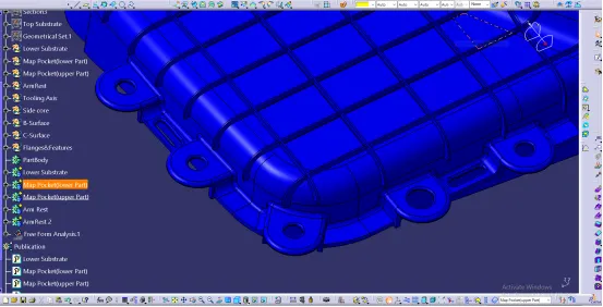
-And Snap fitting feature is created on the surface so ,that Lower map pocket is Attached with the upper map pocket.And also the Ribs are created on the surface to provide More strength to the map pocket.
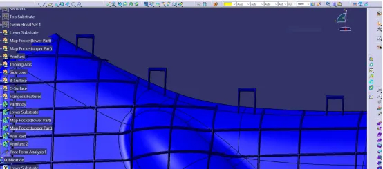
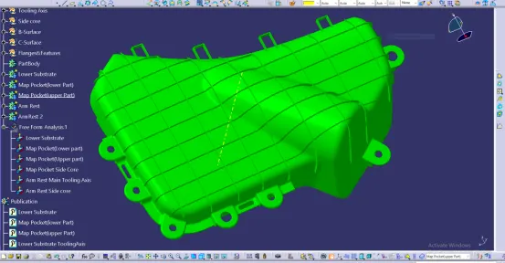
Draft Analysis of Map Pocket Lower Part at 3 degree
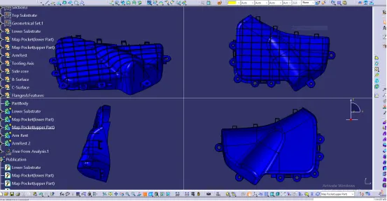
All Multiple Views of the Map Pocket (Lower Part)
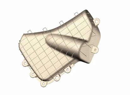
-Armrest
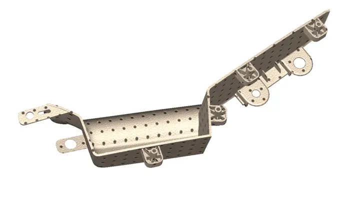
Armrest consist of two split parts. As the tooling was complicated if it manufactured as a single component, I split it into two Parts.
Armrest - Part 1
I extracted the required surface for class A of part 1 from the input surface.
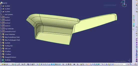
Applied a main tooling axis on the surface for draft analysis
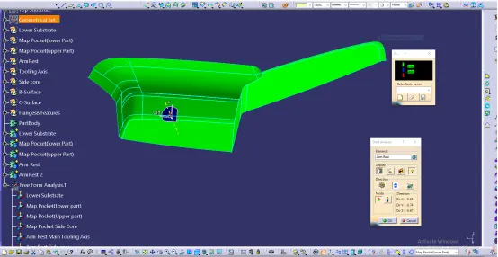
Class B surface was created from the class A surface using 'Extract/MultipleExtract' option. Class B surface was offset at a distance of 2.5 mm thickness from the class A surface.
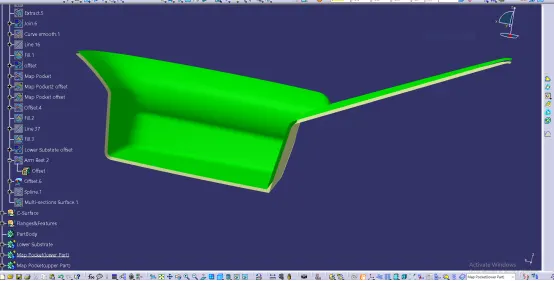
-Class C surface was swept along the boundary of Class A using ' Sweep' option at an angle of 3 degree outwards with respect to main tooling direction. Finallyall the swept surfaces were trimmed and joined together.Class A and Class C surfaces were joined together and trimmed it along with the class B surface. Thus a closed surface was formed as shown below.

Finally, a part body was formed and mounting features were designed for fixing the component. The attachment features such as screw bosses were designed with same tooling direction along the side core axis. Bosses find use in many part designs as points for attachment and assembly. The most common variety consists of cylindrical projections with holes designed to receive screws, threaded inserts, or other types of fastening hardware. As a rule of thumb, the outside diameter of bosses should remain within 2.0 to 2.4 times the outside diameter of the screw or insert.
-Design guidelines for screw boss
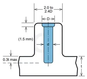
Avoid bosses that merge into sidewalls because they can form thick sections that lead to sink. Instead, position the bosses away from the sidewall, and if needed, use connecting ribs for support.
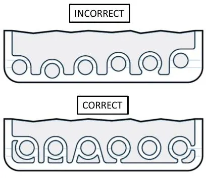
Consider using open boss designs for bosses near a standing wall. Avoid bosses that merge into sidewalls because they can form thick sections that lead to sink. Instead, position the bosses away from the sidewall, and if needed, use connecting ribs for support. Consider using open boss designs for bosses near a standing wall.
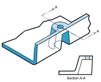
General Guidelines for Screw Bosses
- Draft - 0.5 degrees on walls of boss
- Thickness Typically 60% of nominal wall at base.
- Height to Diameter Ratio - 3:1
- Radii - 0.25mm maximum radii.
- Boss gussets must meet rib guidelines
- Need to plan ahead for type of ejection
- If less than 25mm tall, draft is not required when sleeve ejection is used
- Over 25 mm tall, draft is required on outside wall only if sleeve ejection is used
- If sleeve ejection not used, draft is required on all walls
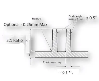
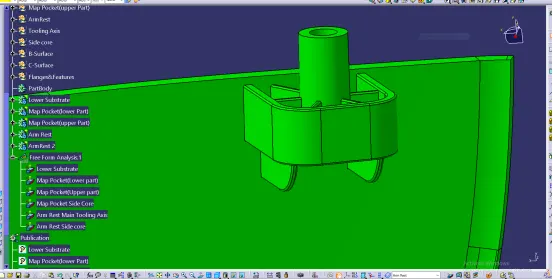
Thus, following all the design guidelines I made the screw bosses for the arm rest. Screw bosses were padded for 12mm height. A draft angle of 0.5 degree was applied on it. Then Screw boss ribs were padded for 10mm height. A draft angle 0.5 degree was applied on them. Then both the screw boss and ribs were union trimmed. 0.25 mm fillets were applied on the screw boss and ribs.
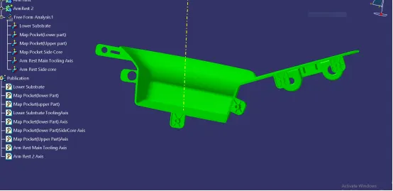
Draft Analysis of Arm Rest Part-1 at 3 degree
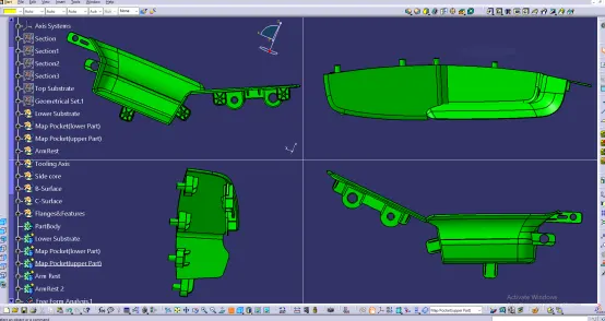
All Multiple Views of the Arm Rest Part-1
Armrest – Part 2
-The second part was also designed as the first one, following the same procedures with two tooling axes
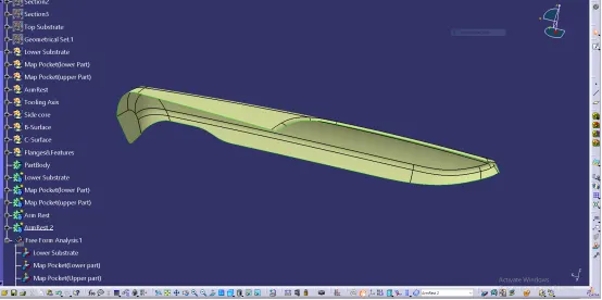
(A surface)
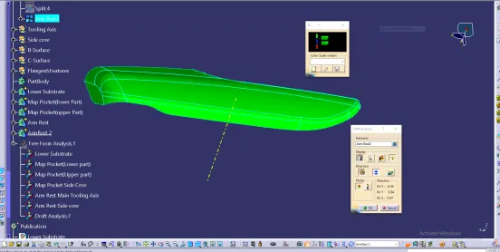
(Draft Analysis at 3 degrees)
-Class C surface was swept along the boundary of Class A using the ' Sweep' option at an angle of 3 degrees outwards with respect to the main tooling direction. Finally, all the swept surfaces were trimmed and joined together. Class A and Class C surfaces were joined together and trimmed along with the class B surface. Thus a closed surface was formed as shown below.
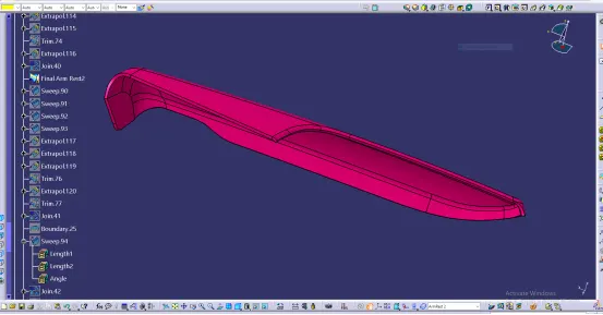
-Finally, a part body was formed and created attachment features on it. The attachment features were successfully cleared along the side core axis.
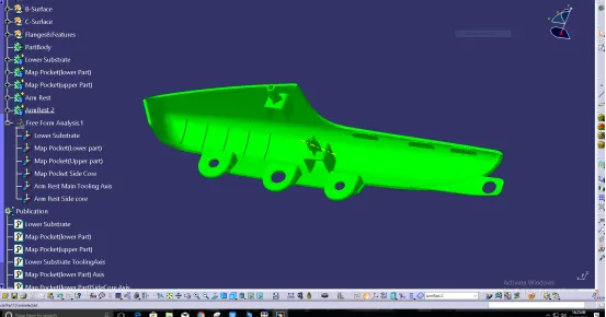
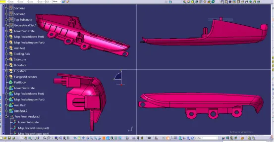
(All Multiple Views of the ArmRest Part-2)
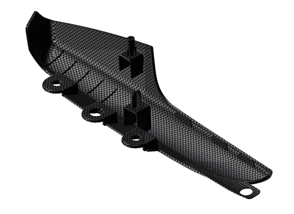
Lower substrate
It is on the lower substrate all the earlier designed components going to fix at first. I extracted the surface for class A from the input surface.
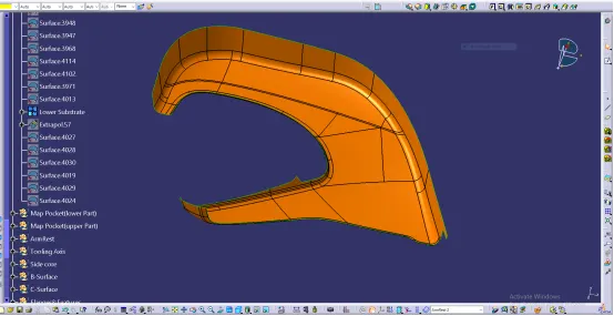
-Draft Analysis of the lower substrate along the main tooling direction is performed. So, There were no issues detected on the class A surface. So I proceeded to further steps for designing the product. The surface was almost flat in shape. I offset it for 2.5 mm for creating the class B as shown on the next page.
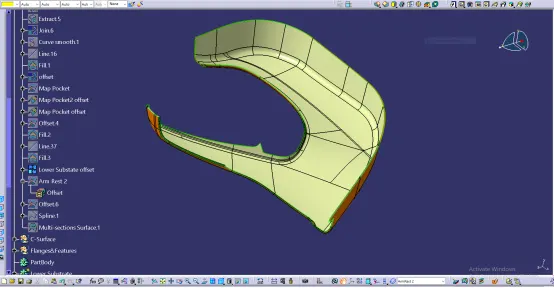
-Class C surface was created using the sweep option. Then I joined both the class A and class C surfaces together and trimmed them along with the class B surface for creating the final closed surface.
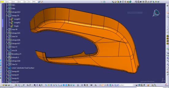
-Then a part body was created using the closed surface and heat stakes with ribs were designed with a 0.5-degree draft, on the B surface side for attaching the map pocket and armrest plastic parts.
Attaching the Map pocket(Lower Part) Attaching the Map pocket(upper Part)
-The Dog House is Created for the mounting of the Retainer clip. The height of the dog house is more So, To Provide the strength to the dog house I had created the Ribs.
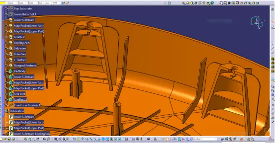
-Dog house is an engineering feature used in the plastic trim design. The primary function of a dog house is to avoid sink marks on the class A surface which may occur due to features such as a locator or rib on the backside of Class. So the best possible solution is to increase the height and decrease the cross-sectional thickness of the ‘legs’ by using a dog house. We can also use them for solving the necessity of large length features such as Heat Stakes And Locators which may require large length sometimes.
-A locking feature is created on the dog house to stop the movement of the Retainer Clip so that the Retainer clip does not come outside when it is mounted on the dog house.
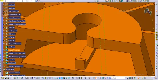
-Retainer Clip is Easy-To-Assemble with BIW Component And Remove Without Special Tools.
-Draft analysis of the product was successfully performed with a minimum 3-degree draft angle.
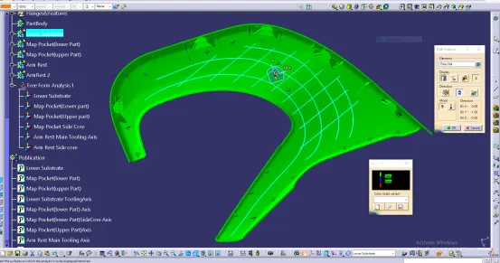
Draft Analysis of the Lower Substrate
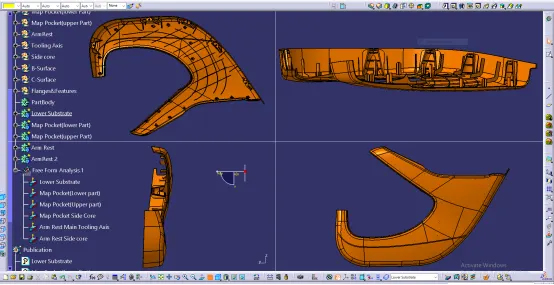
(All Multiple Views of the Lower Substrate)
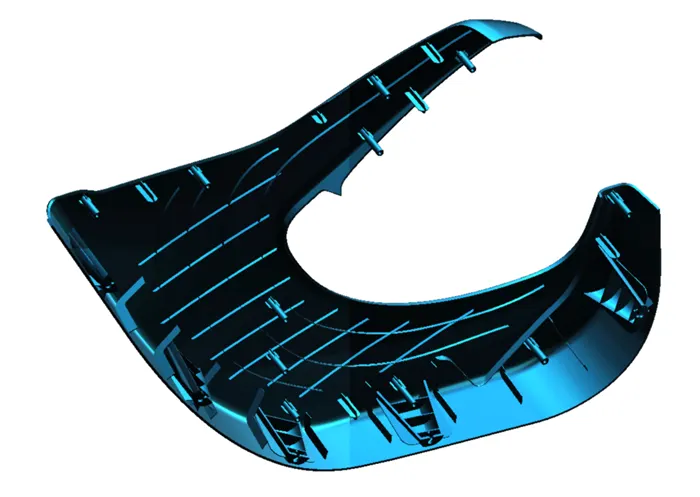
Final product
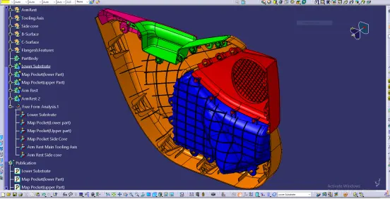
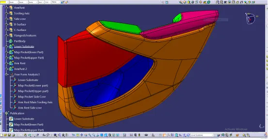
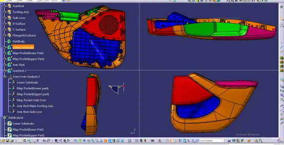
All Multiple Views of the Final Product
Final image renderings of the model