DC Motor Control
Aim:-
- To understand the Speed control of a DC motor BJT-H bridge circuit.
- To study the Four-Quadrant Chopper DC Drive (DC7) block and compare it with the H bridge circuit.
- To do modifications in DC7 in order to get the EV cycle.
Q1.Run MATLAB demo ‘Speed control of a DC motor using BJT H-bridge’. Modify the model such that the Armature current doesn’t shoot up when the motor changes direction from forward to reverse.
Ans:- DC Motor:-A DC motor is any of a class of rotary electric motor that converts direct current electrical energy into mechanical energy. The most common types rely on the forces produced by magnetic fields. Nearly all types of DC motors have some internal mechanism, either electromechanical or electronic, to periodically change the direction of current in a part of the motor.
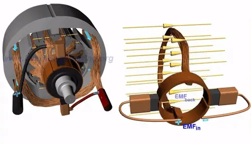
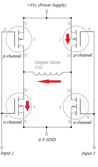
H-Bridge Control:-H-Bridge is one of the most important parts of the DC motor control circuit. It is a device that enables you to change the direction of the motor spin by altering the direction of current flow in the motor.
Speed control of a DC motor using BJT H-bridge:-

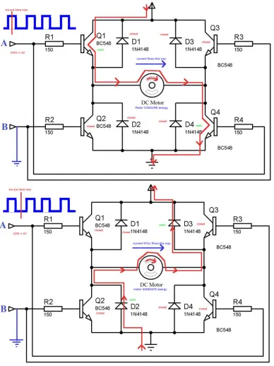
The simulation shown above is for a DC motor using BJT h Bridge. The system is working on the principle of the H bridge circuit. The circuit consists of 4 BJT transistors.
|
Q1 & Q4 active |
Q3 & Q2 active. |
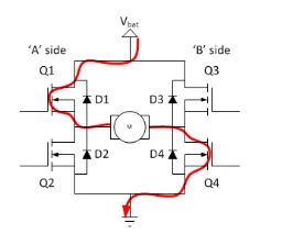
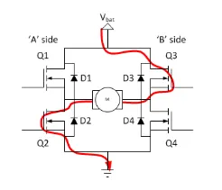
- H bridge is rather a simple circuit, containing four switching elements, with load at the center in an H configuration. The switching elements are generally bi-polar or FET transistors, in some high voltage applications IGBTs. The top end is connected to the power supply and the bottom is generally grounded.
-These BJT are run as either Q1 & Q4 or Q2 & Q3. The Q1 & Q2 are not run simultaneously as this will result in short-circuiting.
- This configuration is used in order to rotate the motor in one direction for some time and in another direction for the next half-cycle. The basic principle consists of 2 PNP and 2 NPN connected along with a diode.
- The input is given by the user in the control signal to control the motor. According to the input the power converter will turn ON/OFF the motor.
- From the plot, it can be seen that there is some shoot up is occurring when the polarities are changed. This change in the reverse direction is more as there is some back emf occurring. In the real-world this back emf is reduced by giving some delay time, this time will reduce the current to 0 and this results in no back emf and this shoot up gets to 0.
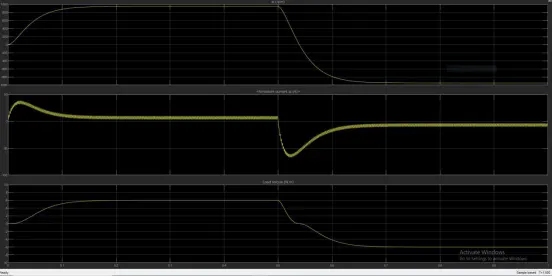
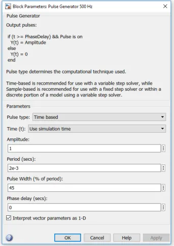
Here just for study purposes, the pulse width is taken as 45.
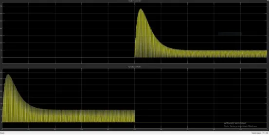
-From the plot, it can be seen that the cycle is working after 0.5 sec. In this case, the input is given for 0.5 to 1sec and that is why the plot is appearing like this. Initially, the pulse width was 75%.
-This means the cycle is on for 75% of the time and off for the remaining 25% of the time.
- In order to satisfy the problem though the pulse width is taken 55, there was some shoot still remaining and in order to remove it, the pulse width is further reduced to 45 and after run this result is obtained.
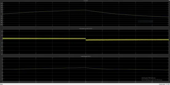
-It can be seen that the speed and load torque also reduces.
-From it can be observed that the motor takes some time to reach the maximum speed. This is due to the load.
- Also it can be seen that the armature current is having a shoot while shifting from 1 direction to another. This is resulting in more compared with the initial half-cycle and that is due to back emf.
- This back emf and shoot is needed to be removed. This can be done by changing the pulse width that means the cycle will run for less time. But this also means that there will be less speed and torque.
Q2.Refer to the help section of ‘The Four-Quadrant Chopper DC Drive (DC7) block’. Compare it with the H-bridge model.
Ans:-
Chopper- Chopper is a basically static power electronics device that converts fixed DC voltage/power to variable DC voltage or power. It is nothing but a high-speed switch that connects and disconnects the load from the source at a high rate to get variable or chopped voltage at the output.
H-bridge model- An H-bridge is an electronic circuit that switches the polarity of a voltage applied to a load. These circuits are often used to allow DC motors to run forwards or backward.
|
The Four-Quadrant Chopper DC Drive (DC7) block |
H-bridge model |
|
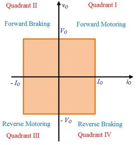
1. A Four-Quadrant Chopper DC Drive (DC7) block is a chopper that can be operated in all four quadrants. |
1. In the case of H-bridge, the Bipolar Junction Transistor (BJT) operates as an IGBT when used for power switching applications. |
|
2. In a four-quadrant chopper, Regenerative Braking can be done |
2. Regenerative braking is not possible. |
|
3. The power can flow either from source to load or load to source |
3. In half-bridge the output voltage waveforms are square, quasi square, or PWM |
|
4. DC chopper device has the advantages of high efficiency, flexibility in control, lightweight, small size, quick response, and regeneration down to very low speed. |
4. An H Bridge inverter will not create a pure sine wave, but rather a ‘modified square wave’. That is to say, a square wave with some off time between the positive and negative transitions. This is just about good enough for powering resistive loads or switched-mode power supplies but is not suitable for inductive loads or other devices that require as pure a sine wave as possible. |
|
5.The Four Quadrant chopper drives it, uses ramps to reduce the shoot up current, and provide stability. |
5. In H-bridge the current shoot-up is high due to switching losses, it can be reduced by changing the pulse width, but it is not. |
|
6.The main Advantage of Four-Quadrant Chopper DC Drive is, it can operate in all four quadrants |
6.H-bridge can operate only in two modes, |
Q3- Make a suitable EV model using DC7 block and make a result report.
Ans:-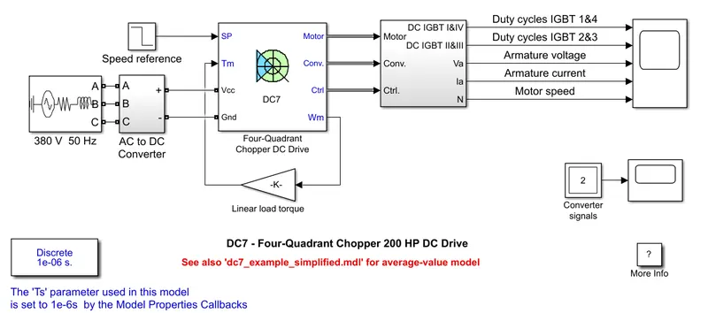
Procedure:-
In accordance to make it suitable EV model,
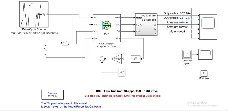
- We know the vehicle speed-torque characteristics, are given by the below equation
- We will put this equation to provide the input Torque, instead of linear load torque, so as to use the actual vehicle speed-torque characteristics.
- The energy source of an EV is a battery, so I use a DC voltage source from Simulink Library
- In according to create an actual environment for the vehicle, I create a Drive cycle in Excel and put it as an input to the vehicle using Drive Cycle BlocK
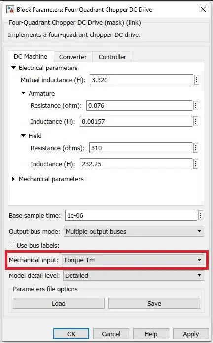
- In order to make a suitable EV model, we edit the DC7 block parameter to give the torque feedback input.
Modified Model-

Result:-
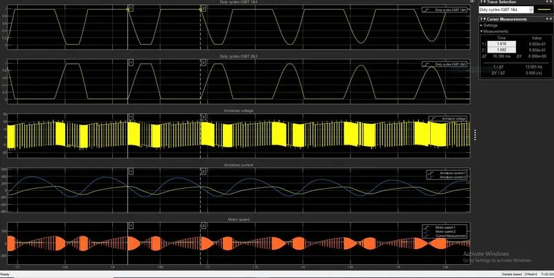
-From the Graph, we take one cycle for study between points 1 & 2,
-We can say that the signal across the IGBT 1 and 4 are increasing than the signal across IGBT 2 and 3 is decreasing during acceleration.
- Operating Voltage remains constant through the cycle.
- It can be seen with the increase in motor speed, the current requirement is also increased, and when motor speed decreases the current drawn from the battery also decreases.
- During the brakes the regenerative braking happens, due to which Armature current goes negative.