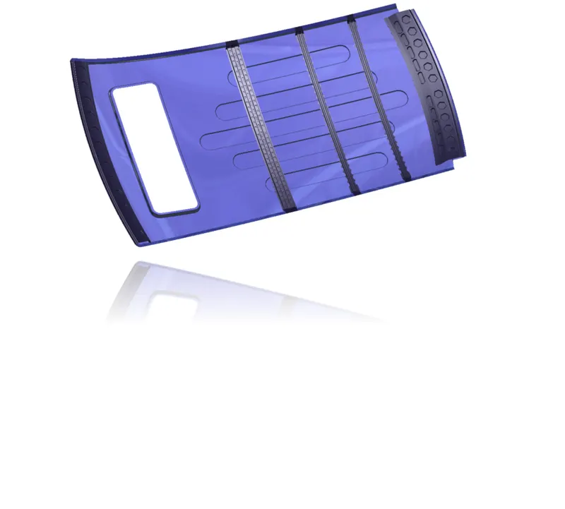
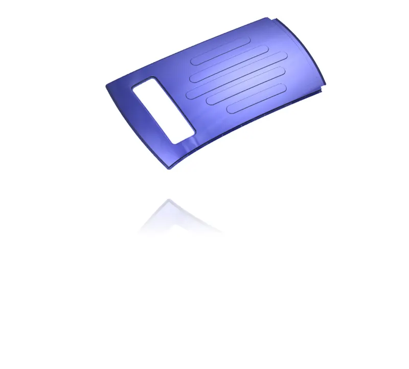
Roof challenge
Aim:
To design & develop the Roof of a car with its components by following the master section and design parameters.
Objective:
- To develop the essential flanges and reinforcements using roof styling as input.
- To do a curvature study on the roof and perform calculations to determine the position of the Bow-roof.
- To determine the Heat Distortion Criteria of the car's roof.
- To find the section modulus on the O-Y section of the roof and also for all the components of it.
- To determine the Snow Load Criteria for a car's roof.
- To perform Draft Analysis on the final CAD model of the roof.
Introduction-
An automobile roof or car top is the portion of an automobile that sits above the passenger compartment, protecting the vehicle occupants from sun, wind, rain, and other external elements. Because the earliest automobiles were designed in an era of horse-drawn carriages, early automobile roofs used similar materials and designs.
Types of Car roofs-
- Convertible roofs
- Hardtops
- Sunroofs
- T-tops
- Targa tops
- Vinyl roofs

Safety point of view vehicle roof plays a very crucial role especially rollover kind of accidents, in which vehicle tips over onto its side of the roof. And vehicle rollover crashes are the cause of many fatalities and several heads, neck, and spine trauma around the world. Therefore, passenger safety is also a very important parameter in front of OEMs. It is not only a marketing strategy but also it is an obligation stipulated by international standards that are now placed in several countries, as well as a governmental requirement.
Rollover crashes, especially in the country, are usually very destructive events. Vehicle damage often includes deformation of the roof and its supporting structures. Head and neck injuries are common and associated with roof deformation. Strengthening of the roof is suggested as an appropriate countermeasure for such injuries.
Types of Rollovers
- Tripped-NHTSA data show that 95% of single-vehicle rollovers are tripped. This happens when a vehicle leaves the roadway and slides sideways, digging its tires into soft soil or striking an object such as a curb or guardrail. The high tripping force applied to the tires in these situations can cause the vehicle to roll over. E.g. Soft soil, Guardrail, Steep Slope
- Un-Tripped -Un-tripped rollovers are less common than tripped rollovers, occurring less than 5% of the time, and mostly to top-heavy vehicles. Instead of an object serving as a tripping mechanism, un-tripped rollovers usually occur during high-speed collision avoidance maneuvers.
For this reason, strength is a very important criterion for designing a vehicle roof.
FMVSS 216 Roof crush standards-
FMVSS 216, Roof Crush Resistance, establishes strength requirements for the passenger compartment roof of passenger cars, multipurpose passenger vehicles, trucks and buses with a GVWR of 2722 kilograms or less. The purpose of the standard is to reduce deaths and injuries due to the crushing of the roof into the passenger compartment in rollover accidents. The standard does not apply to school buses and passenger cars that conform to the dynamic rollover test requirements of FMVSS 208, Occupant Crash Protection, and S5.3 by means that require no action by passenger car occupants. It also does not apply to convertibles, except for optional compliance with the standard as an alternative to the rollover test requirements in S5.3 of FMVSS.
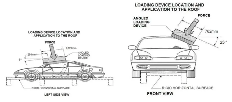
The prescribed static loading device is a rigid unyielding rectangular block 762 millimeters by 1,829 millimeters. It shall not move more than 127 millimeters to achieve the specified resistive load when applied to the forward edge of a vehicle’s roof – see Figures 1 and 2. The resistive load to be achieved is 1½ times the unloaded vehicle weight (UVW) of the test vehicle or 22,240 Newtons, whichever is less.
The force shall be applied in a downward direction perpendicular to the lower surface of the static loading device at a rate of not more than 13 millimeters per second until reaching the compliant resistive load. The test shall be completed within 120 seconds. The static loading device shall be guided throughout the test so that it moves, without rotation, in a straight line with its lower surface oriented as follows and as shown in Figures
Following are the design considerations of the roof-
- Visibility criteria
- Head clearance
- Heat distortion and snow load criteria
- Draft analysis
- Safety parameters
Input data from styling team-
We will be having the following data which is provided by the styling team.
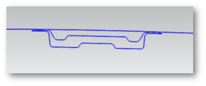
-A- the surface of the roof along with railing rack
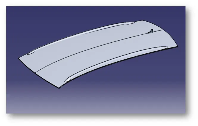
-Master sections for various rails.like the Master section for the Rear roof rail.
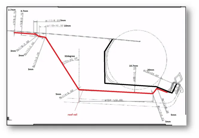
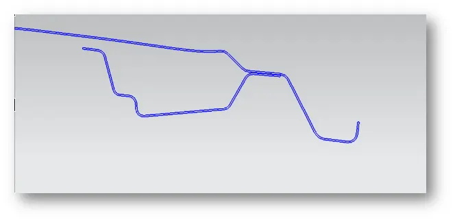
-Master section for Front roof rail
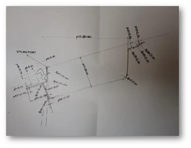
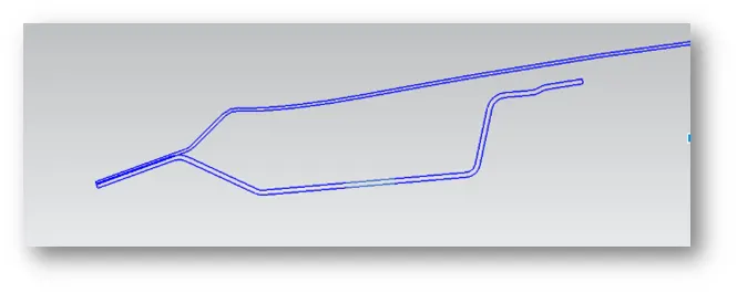
-Master section of reinforcement center
-Heat Distortion Criteria:
The heat radiating from the sun causes the roof of the car to change in the metallic regions. Heat distortion criteria indicate what temperature materials start to "soften" when exposed to a fixed load at elevated temperatures.
W = [1.73 x 10^(-3) x L] + [1.85 x 10^(-8) x (R^2)/t] + [ 1.10x10^(-3) x l] - 2.68
Judgement Condition : OK< 2.7> 3.1
Where
L = Roof Length in X-Direction[mm](Roof dimension in 0-Y)
R = Roof curvature
R = 2(Rx*Ry)/(Rx+Ry)
Rx = X curvature
Ry = Y curvature
t = Roof plate thickness [mm]
l = Bow Roof Span [mm]
-Snow Load Criteria:
During Winter Season the snow gets clogged over the top surface/roof of the car and the snow has some mass on it. Due to this, the roof can fail if the snow load exceeds the capacity of the roof that was designed to sustain.
Qr = [Iy x t2] / [α x s x [(Rx + Ry)/2]2 x 10-8]
Note: The Qr value given over here is correct. There was a typo error in the formula given in the video.
Where
α = My x Lx2 x 10-12 , My = Y(Ly-Y)
Judgement condition = Qr ≥ 3.1
250 ≤ s ≤ 380
t = Roof plate thickness [mm]
Ly = Distance between the front and rear roof Rails on the Vehicle along with 0Y[mm]
Length of Roof panel with the center point between Roof rail Front /Rear as the reference point of the front and the rear.
Lx = Distance between the Left and Right end of the roof on the Roof BOW [mm]
Width of the roof panel exposed on the surface.
Y = Distance front Front Roof Rail to Roof BOW[mm]
s = Distance for which Roof BOW bears divided load [mm]
s = L1/2 + L2/2
Iy = Geometrical moment of inertia of Roof BOW (Y cross-section )[mm4]
Rx = Lateral direction curvature radius of roof panel Y cross-section on Roof BOW [mm]
Roof panel curvature Radius of the Length Lx in Front view
Ry = Longitudinal Direction curvature radius of the Roof panel X cross-section on Roof BOW [mm]
Roof panel X curvature radius of length s in Side view
Section Modulus:
Section modulus is a geometric property for a given cross-section used in the design of beams. Other geometric properties used in the design include an area for tension, radius of gyration for compression, and moment of inertia for stiffness. The Section modulus is defined as
S=IyS=Iy
Where
S = Section Modulus
I = Moment of Inertia
y = Distance from the neutral axis to any given part.
Procedure:
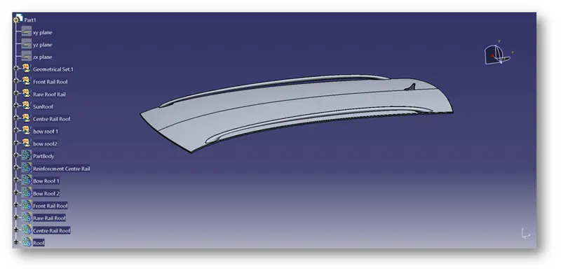
- Checking the Class –A surface:
-After the file is opened, the roof part is not joined together but as the individual surfaces.
-It is also seen as the surface is perfectly symmetrical in shape which helps us to work on the half of the portion and reflect it which creates the whole roof.
- Creating the Flanges for the Roof:
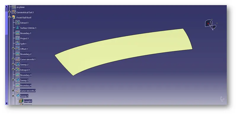
-Extract the upper roof part by selecting it. and then Untrim the extracted surface
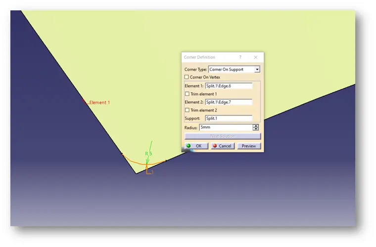
- Now, since it is a sharp corner at the end to make it smooth, use the corner option to create a cut on the edges and split it to create the smooth corner.
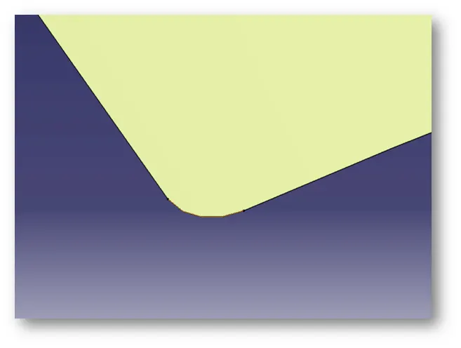
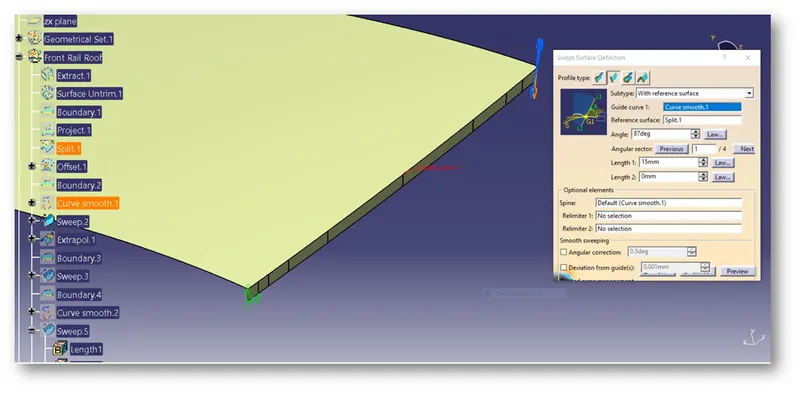
-Now select an edge and sweep it with the 3-degree draft with a length of 15mm.
-From the edge of the sweep take another sweep with the 25 degree draft of length 21.5 mm (as shown in the reference dimensions).
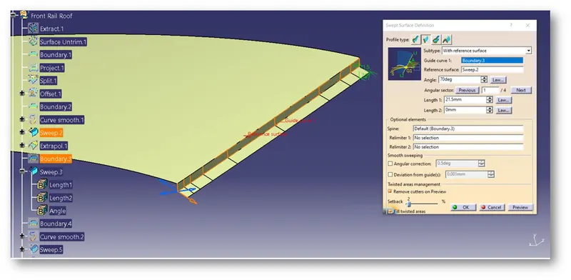
-Follow the same procedure with the other edges.
-Now, create the curved edges by using curves as the guide curves and the multi-section surface option.
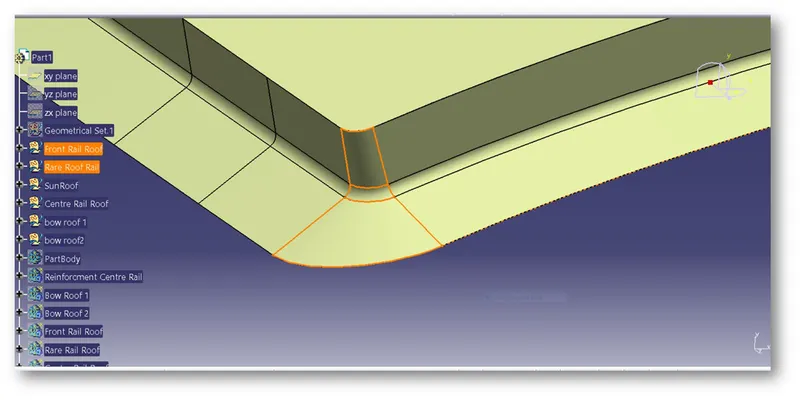
-Join the Surfaces together and give the fillets.
-For the Rear end, there should be an additional area that helps to hold the back door without hitting the roof.
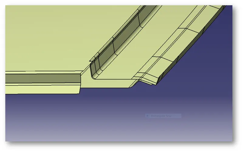
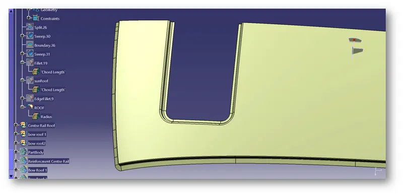
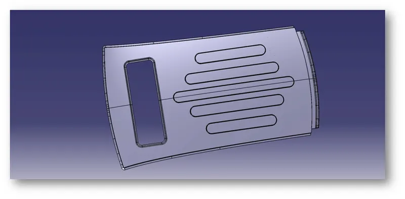
-For Creating the Sunroof, the Sketch is created and then projected onto the Roof. Now, the projected element is split and the sweep is done on the free edges.
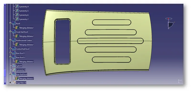
-After creating the sunroof, embosses are given on the roof to provide better strength. A sketch is drawn and projected on the surface.
-The Roof is then split with the projected area. And then the embosses are created.
-after creating the embosses. the embossed surface is then mirrored on the other side.
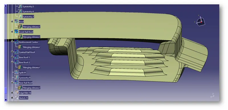
- Creating the Front roof Rail:
-Offset the roof to 2.7mm and split it with a distance of 5mm.
-Similarly, create an offset of 4.7mm and cut it.
-Now create a base offset of 32mm from the roof.
-Create the respective sweeps for these offsets and trim them together.
-Give the Edge fillets to it.
-After that embosses are created on this to provide more strength.
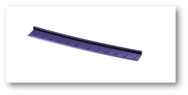
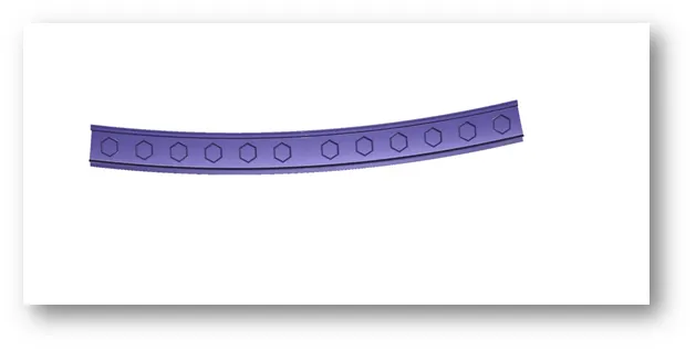
Front Side Back Side
- Creating the Rear roof Rail:
-For the rear roof, rail follows a similar procedure as the front roof and the values for it are given in the diagram.
-Make sure that the Rear roof has a positive draft angle.
-After that embosses are created on this to provide more strength.
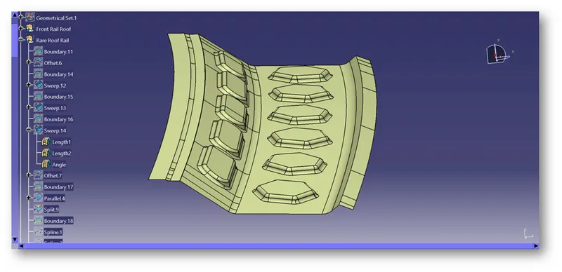
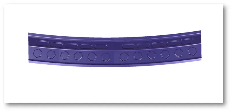
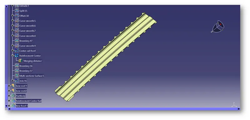
- Creating the Centre Reinforcement:
-The Centre Reinforcement is attached at the center yet below the roof.
-To create the center reinforcement as per the diagram, we use the offset and select the parallel curve option and give an offset value of 50mm on both sides and create a cut on the offset.
-Now create the part as per the design standards and make sure that the offset is given considering the thickness of the component.
-And the edges of the surface is removed to reduce the material cost. and Also Provided an appropriate area for Mastic Sealant.
-A dip area needs to be created so that the reinforcement is attached to the roof flange.
-To create that area, select the flange and create an offset to the length including the thickness of the roof and the connecting parts.
-Cut the Offset to the length which is less than the width of the center reinforcement.
-Create lines on the cut surface.
-Use connect option to join the lines to form curves.
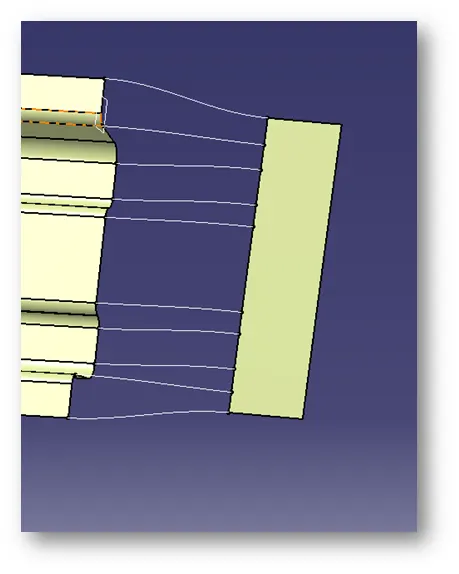
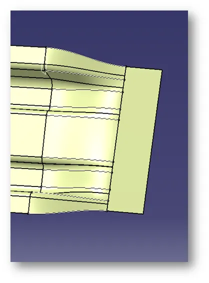
-Use the Multi-section surface option to select the edges and the curves created as the guide curves to create a body.
-Join the surfaces together
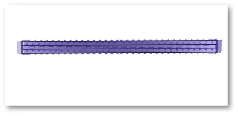
- Creating the Bow roofs:
-3 bow roofs are created to give strength to the roof.
-Follow the same method as with the center reinforcement to create the bow roof.
-Now, after the bow roof is created. The mastic points need to be created.
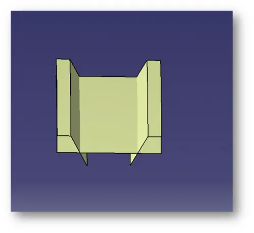

-Once created use the split option to create the mastic points.
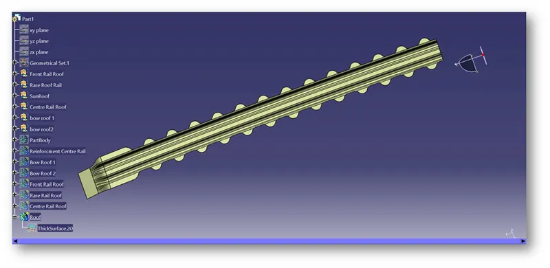
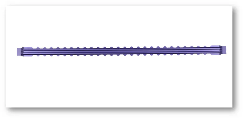
- Creating a Solid:
- After Creating the surfaces, use the thicken option to create the solids with the proper thickness.
- The thickness for the Roof And all other parts is Considered 0.75mm.
- Checking the Heat Distortion criteria:
-To calculate the Heat distortion criteria, we have to take note of few values and note it down.
-To note down, first, we need to create a sketch.
-Create a line at the centre of the roof part in the 0-Y axis and then draw another line with a distance of 300mm.
-Now create the line with a distance of 100 on both sides at the line which is at 300mm.
-Now create the line between the rails in the X direction and create 2 lines with a distance of 100mm on both sides.
-Now create a point coinciding with both the lines.
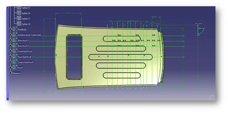
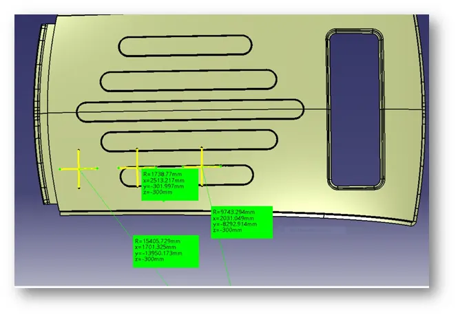
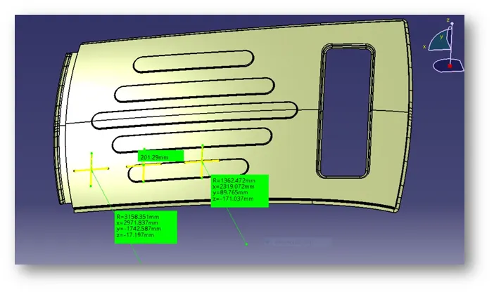
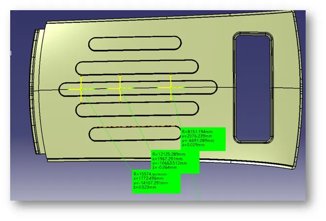
-Extract the points to the roof and create the arc using 3 points by creating two lines intersecting with each other.
-Measure the radius of the arc in the Y direction as Ry, Ry and X direction as Rx, Rx.
-Ry, Ry Value:
-Rx, Rx Value:
- Checking the Snow Load Criteria:
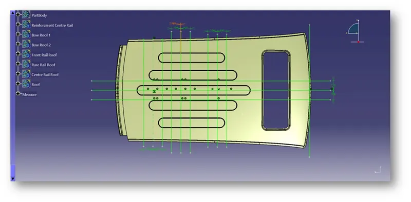
-To calculate the Snow Load criteria, we have to take note of few values and note it down.
-To note down, first, we need to create a sketch.
-Create a line at the center
of the roof part in the 0-Y axis.
-Now create the line with a distance of 100 on both sides.
-Now create the line between the rails in the X direction and create 2 lines with a distance of 100mm on both sides.
-Now create a point coinciding with both the lines.
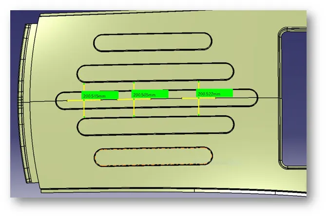
-Extract the points to the roof and create the arc using 3 points by creating two lines intersecting with each other.
-Measure the radius of the arc in the Y direction as Ry, Ry, and X direction as Rx, Rx.
-Rx. Rx Value:
-Ry, Ry Value:
- Checking the Section Modulus:
- To check the section modulus, we need to create the intersection in the Y-axis.
- After the intersection is done, fill the surface with the intersection created.
- Select the Measure Inertia option to measure the 2D inertia of the surface created.
- Note down the values.
Calculation:
Heat Distortion Criteria:
We need to find the heat distortion criteria for the following.
L value:
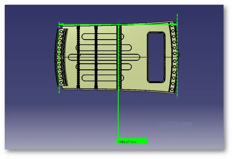
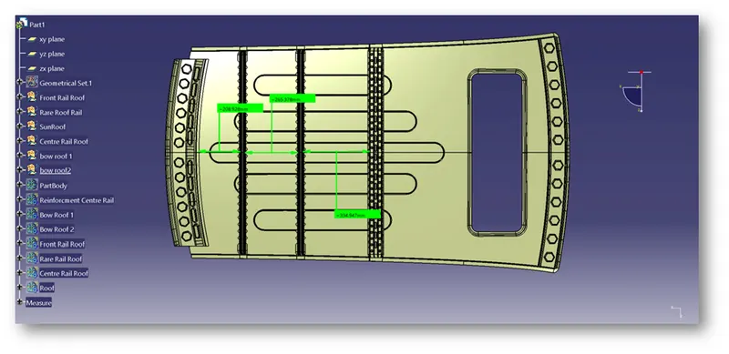
'l' value:
Calculating Heat Distortion Criteria by using given Formula:
W = [1.73 x 10^(-3) x L] + [1.85 x 10^(-8) x (R^2)/t] + [ 1.10x10^(-3) x l] - 2.68
Judgement Condition : OK< 2.7> 3.1
Where,
L = Roof Length in X-Direction[mm](Roof dimension in 0-Y)
R = Roof curvature
R = 2(Rx*Ry)/(Rx+Ry)
Rx = X curvature
Ry = Y curvature
t = Roof plate thickness [mm]
l = Bow Roof Span [mm]
-Here I’m Calculating the value of Roof Curvature By using excel calculator
R = 2(Rx*Ry)/(Rx+Ry)
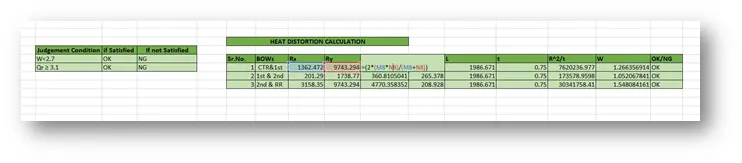
-Here I’m Calculating the value of R^2/t
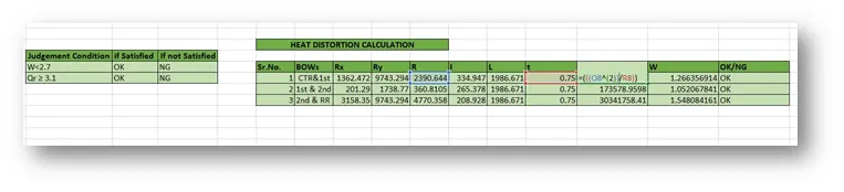
- Here I’m Calculating the Heat Distortion Criteria by using by using excel calculator
W = [1.73 x 10^(-3) x L] + [1.85 x 10^(-8) x (R^2)/t] + [ 1.10x10^(-3) x l] - 2.68

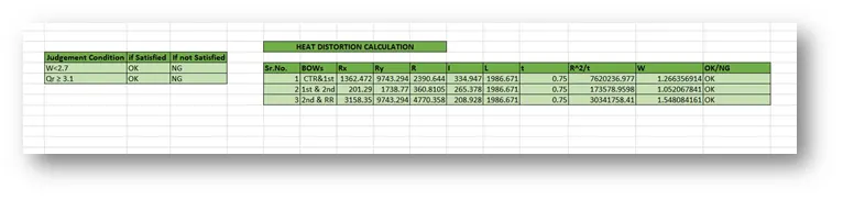
-Here I’m Checking the Judgement Condition of Heat Distortion Criteria by using an excel calculator
If the value of W is satisfying this condition OK< 2.7 then it’s represented by OK. It’s Means Roof Fulfilling the conditions of Heat Distortion Criteria.
Or If the value of W is not satisfying this condition OK< 2.7 then it’s represented by NG. This means the Roof not Fulfilling the conditions of Heat Distortion Criteria. So, the Styling surface is Forwarded to the Styling Team. Here the stage at which the roof is not satisfying is needed to be modified in a gradual way.

-Calculation of Heat Distortion Criteria by using excel calculator
Calculating Snow Load Criteria:
During Winter Season the snow gets clogged over the top surface/roof of the car and the snow has some mass on it. Due to this, the roof can fail if the snow load exceeds the capacity of the roof that was designed to sustain.
Qr = [Iy x t2] / [α x s x [(Rx + Ry)/2]2 x 10-8]
Note: The Qr value given over here is correct. There was a typo error in the formula given in the video.
Where
α = My x Lx2 x 10-12 , My = Y(Ly-Y)
Judgement condition = Qr ≥ 3.1
250 ≤ s ≤ 380
t = Roof plate thickness [mm]
Ly = Distance between the front and rear roof Rails on the Vehicle along with 0Y[mm]
Length of Roof panel with the canter point between Roof rail Front /Rear as the reference point of the front and the rear.
Lx = Distance between the Left and Right end of the roof on the Roof BOW [mm]
Width of the roof panel exposed on the surface.
Y = Distance front Front Roof Rail to Roof BOW[mm]
s = Distance for which Roof BOW bears divided load [mm]
s = L1/2 + L2/2
Iy = Geometrical moment of inertia of Roof BOW (Y cross-section )[mm4]
Rx = Lateral direction curvature radius of roof panel Y cross-section on Roof BOW [mm]
Roof panel curvature Radius of the Length Lx in Front view
Ry = Longitudinal Direction curvature radius of the Roof panel X cross-section on Roof BOW [mm]
Roof panel X curvature radius of length s in Side view
Section Modulus:
Section modulus is a geometric property for a given cross-section used in the design of beams. Other geometric properties used in the design include an area for tension, radius of gyration for compression, and moment of inertia for stiffness. The Section modulus is defined as
S=I/y
Where
S = Section Modulus
I = Moment of Inertia
y = Distance from the neutral axis to any given part.
-Here I’m Calculating the value My = Y(Ly-Y) By using an excel calculator 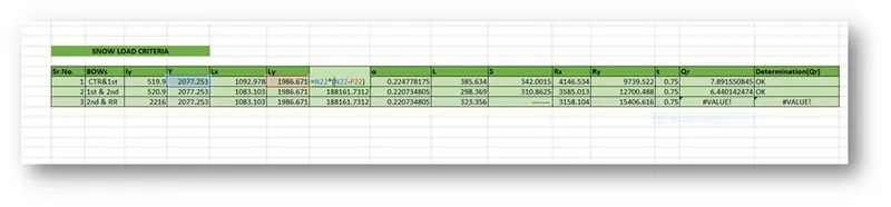
- Here I’m Calculating the value of α = My x Lx2 x 10-12
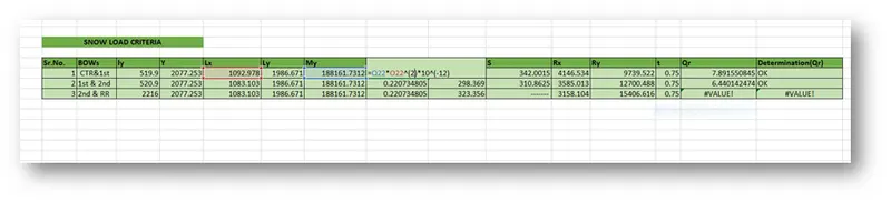
- Here I’m Calculating the Snow Load Criteria by using an excel calculator
Qr = [Iy x t2] / [α x s x [(Rx + Ry)/2]2 x 10-8]
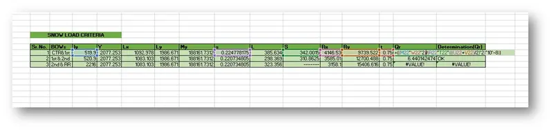
-Here I’m Checking the Judgement Condition of Snow Load Criteria by using an excel calculator
If the value of W is satisfying this condition OK< 2.7 then it’s represented by OK. It’s Means Roof Fulfilling the conditions of Snow Load Criteria.
Or If the value of W is not satisfying this condition OK< 2.7 then it’s represented by NG. This means the Roof not Fulfilling the conditions of Snow Load Criteria. So, the Styling surface is Forwarded to the Styling Team. Here the section at which the roof is not satisfying is needed to be modified in a gradual way.

-Calculated Heat Distortion Criteria by using an excel calculator
Section Modulus:-
For Bow Roof Rail 1:
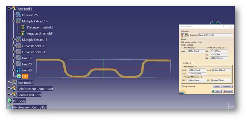
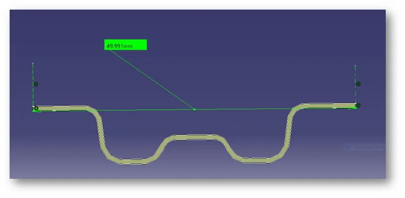
S=I/y
Where
I = 5.199e-010m4=519.9 mm^4
y = 49.991/2=24.995mm
S =I/y=519.9/24.995= 20.8mm^3
S = 20.8mm^3
For Bow Roof Rail 2:
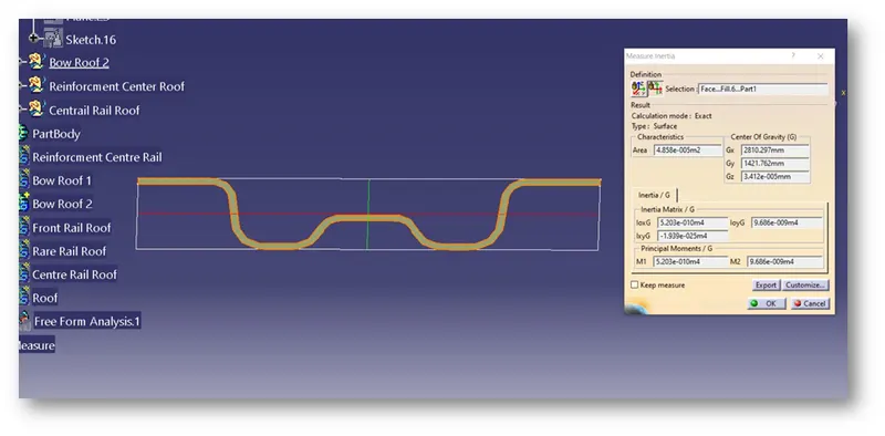
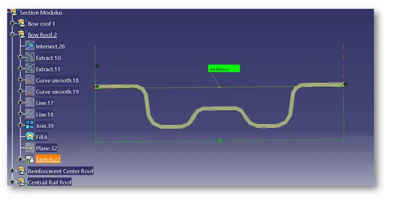
S=I/y
Where
I = 5.203-010m4=520.3 mm^4
y = 49.993/2=24.996mm
S =I/y=520.3/24.996=24.995mm^3
S= 24.9965mm^3
For Central Bow Roof :-
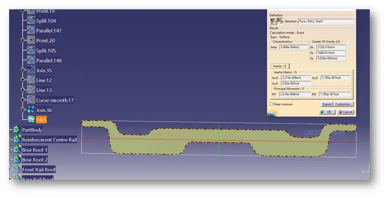
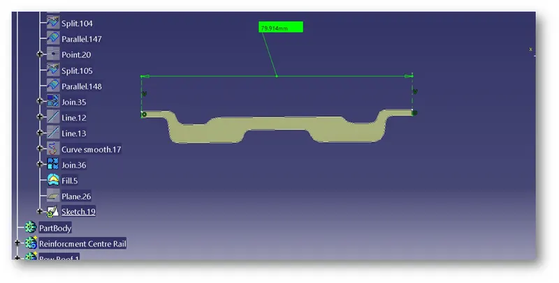
S=I/y
Where
I = 2.216-009 m4=2216 mm4
y = 79.914/2=39.957mm
S =I/y=2216/39.957=55.459mm
S =55.459mm
For Center Reinforcement:
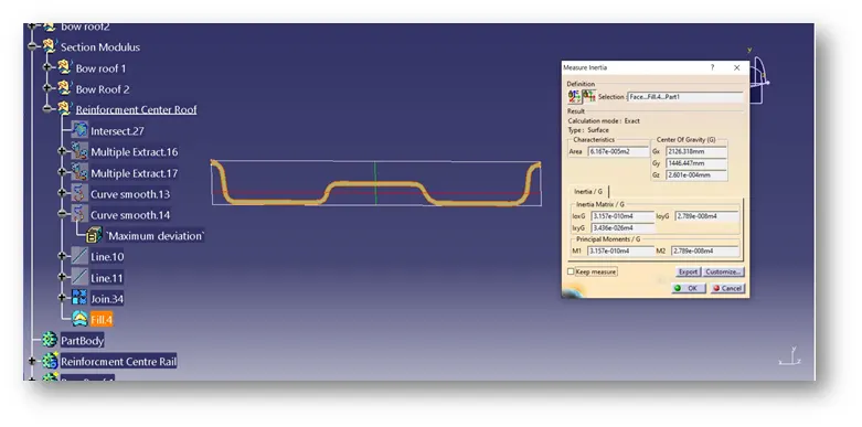
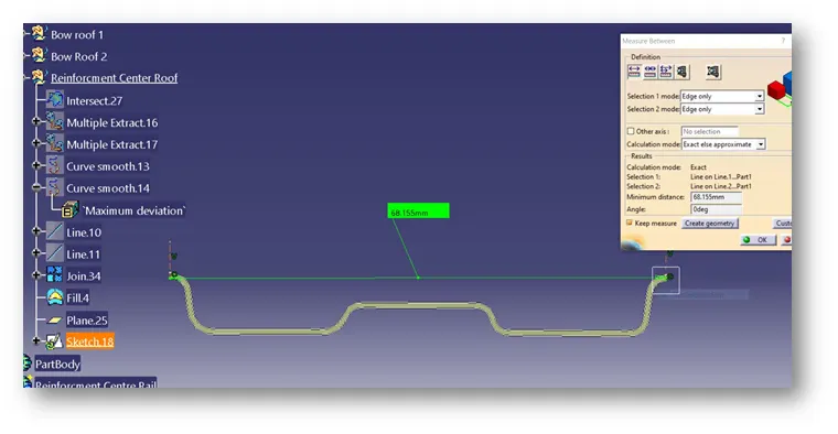
S=I/y
Where
I = 3.157e-10M^4= 315.7mm^4
y = 68.155/2= 34.055mm
S =I/y=315.7/34.055=9.27mm^3
S = 9.27mm^3
Section Modulus:
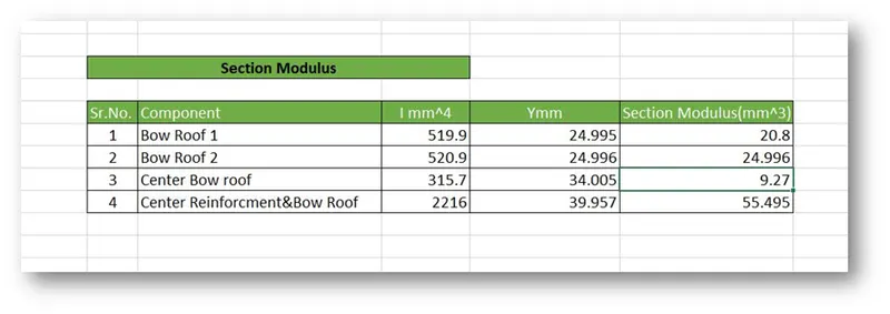
The above table shows that the model passes all the criteria. Some modifications can be done by changing the position of the bow roofs to increase the strength of the roof even further.
Draft Analysis:
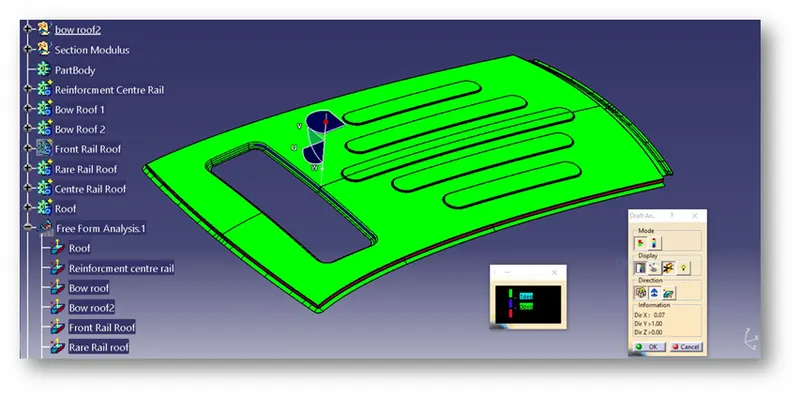
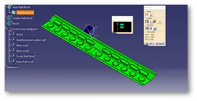
The Draft analysis is done on the individual Parts to check if is passing the criteria.
Roof:
Front Roof Rail:
Center reinforcement:-
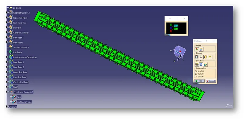
Cantrail bow roof:-
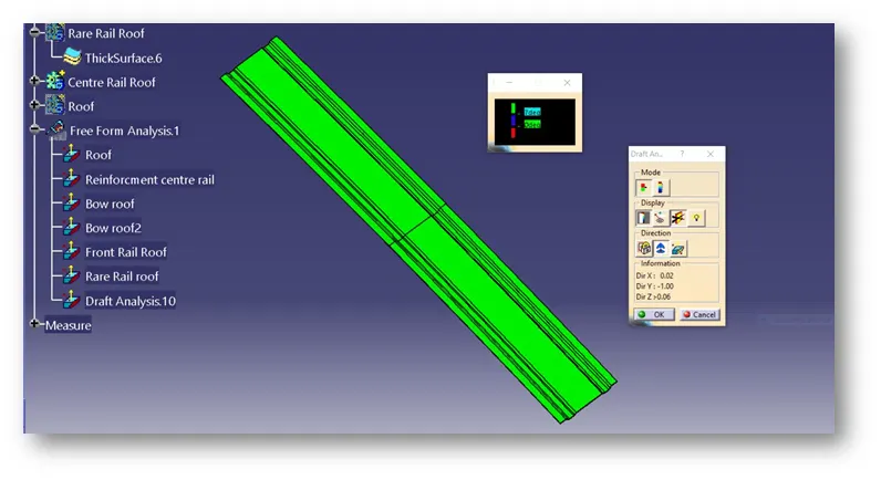
Bow Roof 1:
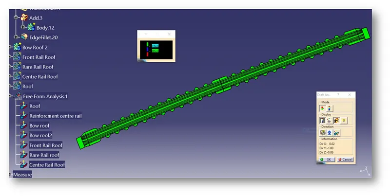
Bow Roof 2:
Final Model:
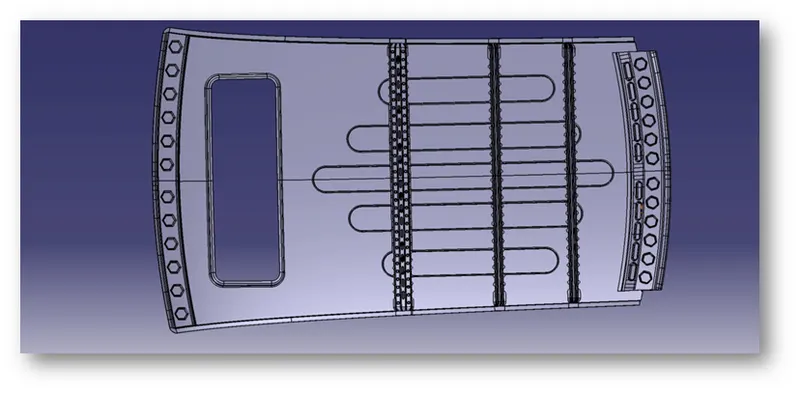
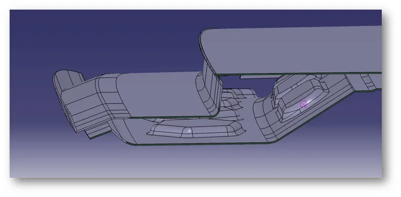
Section Views:
Front Roof Rail:
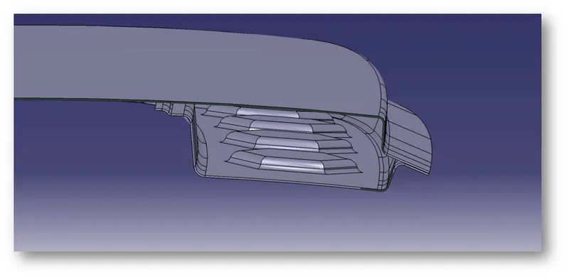
Center Reinforcement and Bow Roof 1:
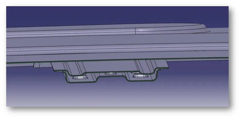
Bow Roof 2 and 3:
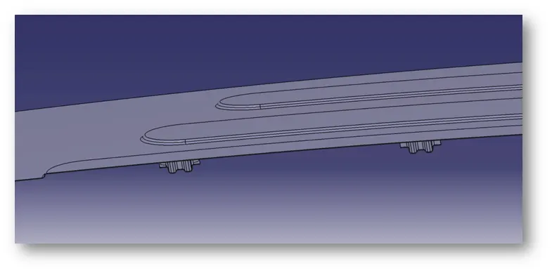
Rear Roof Rail:
Learning Outcome:
- Learned how to create rails as per the design.
- Learned how to calculate and what are the criteria for the Heat Distortion, Snow Load conditions.