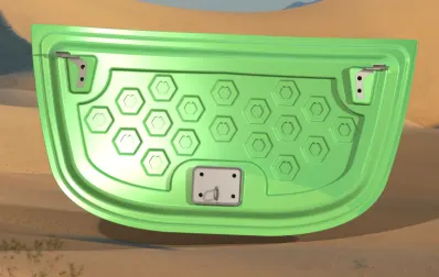
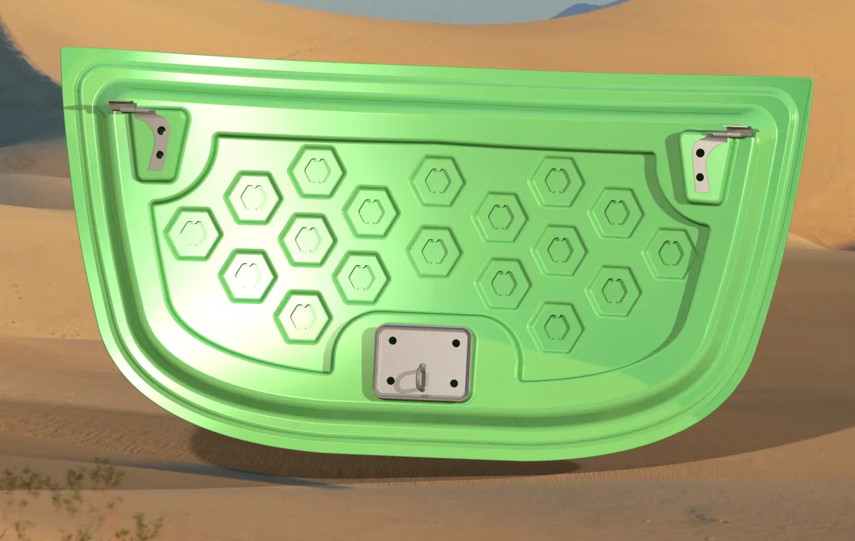
Hood design
Aim:
To create an outer and inner hood panel, positioning the stiker, hinge and their reinforcements.
Data to be used:
Hood Thickness Information
- Outer Panel Thickness = 0.75mm
- Inner Panel Thickness = 0.75mm
- Reinforcement Thickness = 1.5mm
Master sketch:
Hemming Data:
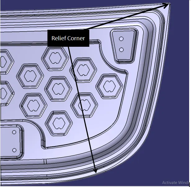
Relief rear section: Front relief:
Hood:-Hood plays a major role in pedestrians safety as well as car safety. It covers entire engine components and also acts as a shield to the pedestrians from the major injury. Hood has different styles.On front-engined cars, the hood may be hinged at either the front or the rear edge, or in earlier models it may be split into two sections, one each side, each hinged along the centre line. A further variant combines the bonnet and wheel arches into one section and allows the entire front bodywork to tilt forwards around a pivot near the front of the vehicle.
Hoods are typically made out of the same material as the rest of the body work. This may include Steel , aluminium ,fiberglass or carbon-fiber. However, some aftermarket companies produce replacements for steel hoods in fiberglass or carbon fiber to make the vehicle lighter
The components include in the hood was
1)Latch trajectory:-This is the part of the hood that has a trajectory or hook type design used to lock or unlock from the vehicle engine compartment.
2)Hinge assembly:-This hinge was placed on the hood to give rollover action to tilt up or tilt down the hood.
3)Mastic seal:-This seal used to attach the inner and outer panel instead of welding(welding gives spots on the surface which give an aesthetic look on the surface, that's why the mastic seal was introduced).
Each mastic point in the fixture covers over 80mm dia to stick together between inner and outer panel.
SAFETY REQUIREMENT WHILE DESIGNING HOOD
Safety is the most important criteria in automobile designs which concentrates on both pedestrian and occupant safety. The pedestrians are the most vulnerable road users and are at high risk of traffic accidents. The major reason for the fatality of the pedestrian in traffic accident is due to the head injury resulting from the hard impact of the head against the stiffer hood or the ground. This leads to the necessity of new inner hood panel which is less stiffer and pedestrian friendly.
The head impact analysis on the present hood of the car was done to study the response of the adult head form at two different locations. Structural and modal analysis for the same present hood assembly was done to observe the local and global stiffness. In order to reduce the head injury of the pedestrian the local stiffness over the area of head impact has to be reduced thus the new design of hood inner panel was focused on that and the structural and model analysis was done for the new design. The design with lesser local stiffness and similar global stiffness compared to the existing hood was finalized.
Vehicle safety factors should simultaneously consider occupant and pedestrian safety, given that pedestrians are the third largest category of traffic fatalities. Most pedestrian deaths occur due to traumatic brain injury, resulting from the hard impact of the human head against the vehicle's stiff hood or windshield.
Therefore, how to design a pedestrian-friendly vehicle and propose a new hood structure is a matter of urgency for minimising pedestrian head injuries.
In this study, three kinds of sandwich hood structures are proposed for reducing pedestrian head injuries, including carbon fibre-reinforced polycarbonate, carbon fibre-reinforced foam and aluminium-reinforced polycarbonate.
The finite element method is used to simulate the impact between the vehicle's hood and the headform impactor. The software used in simulation is LS-DYNA. The results predicted by the headform-hood tests show that the hood structure with aluminium-reinforced polycarbonate material provides enough absorption capability to protect pedestrians from the impacts of accidents. It is also stiff enough to keep pedestrians' heads away from the inner parts of the engine cavity.
Child Head Impact:
Car-pedestrian accidents account for a considerable number of automobile accidents in industrialized countries. Head injury continues to be more concerned with Automobile impacts. Because the head is the most seriously injured part in many collisions including in pedestrian automobile collisions. To reduce the severity of such injuries international safety committee have proposed subsystem tests in which head foam impactors are impacted upon the car hood
Currently in India, Automotive Indian Standard (AIS) 100, Amendment 1 is used to evaluate the performance of vehicles against pedestrian safety. This standard has been harmonized from the international evaluation standard Global Technical Regulation No. 9 (GTR 9), whose purpose is to bring about an improvement in the construction of the fronts of vehicles and, in particular, those areas which have been most frequently identified as causing injury when in collision with a pedestrian or other vulnerable road user. The tests required are focused on those elements of the child and adult body most frequently identified as sustaining an injury, i.e. the adult head and leg and the child's head. To achieve the required improvements in the construction of vehicles, the tests are designed in such a way that they will represent the rear world accident scenario.
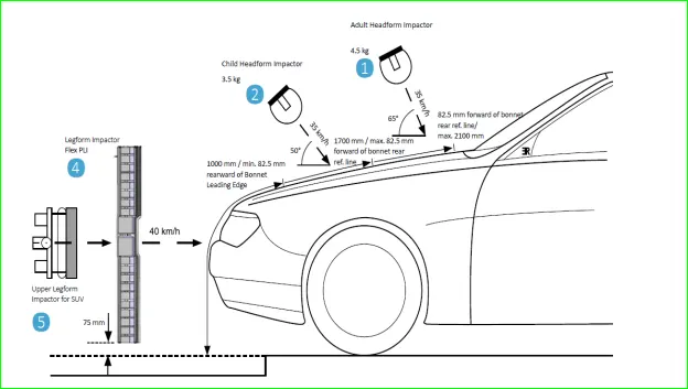
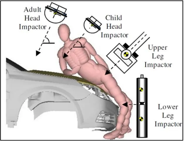
Fig: Pedestrian Protection Test Procedures as per AIS 100
The different impactors used in predicting the performance against pedestrian safety are the lower leg form and upper leg form impactors (representative of the adult leg) and the adult and child head form impactors (representative of the adult head and child's head). Head injury is a more life-threatening and most common cause of pedestrian deaths in pedestrian to vehicle collision; it was decided to focus on these impactors and test procedures as a part of this study.
Wrap Around Distance (WAD):
When a car crashes on the pedestrian, the whole human body wraps around the front shape of the car, and the head impacts on the bonnet or the windscreen. The distance at which the head impacts on the car from the ground is mentioned as Wrap Around Distance (WAD).
To be specific the Wrap Around Distance is a measurement of the distance from the ground to the head impact zone over the outer surface of the car. The wrap-around distance is measured longitudinally in the center of the vehicle from the ground.
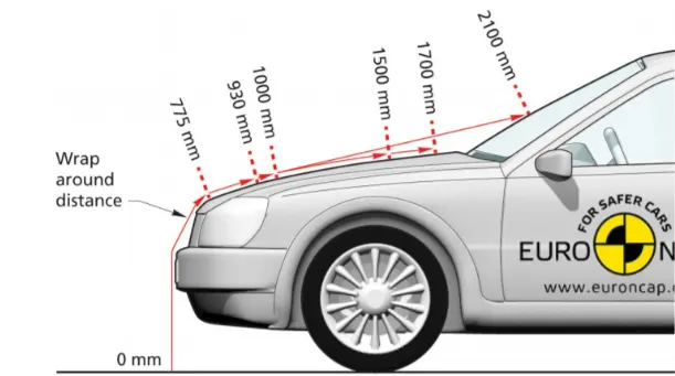
Fig: Euro NCAP - WAD
The severity of the injury caused by the frontal crash depends on the type and shape of the vehicle, the speed of the vehicle, and the movement of the pedestrian relative to the vehicle. In addition to these parameters, the wrap-around distance plays a major role in the safety measures of a pedestrian
During the crash analysis, based on the Wrap Around Distance(WAD), two test areas will be created namely the Child head impact zone and the Adult head impact zone. The child head impact zone is between 1000 to 1700 mm WAD and the adult head impact zone ranges between 1700 to 2100 mm WAD.
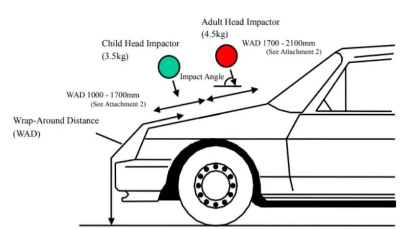
Fig: WAD zone
Head injury criteria (HIC)
The head foam impactors are used to test the behavior on vehicle structures such as the hood. In a pedestrian-vehicle impact, the kinematics and severity of pedestrian injuries are affected by the impact locations on the vehicle and body velocities after impact. The objective of this project is to analyze the pedestrian kinematics in a Pedestrian-Car accident scenario and determine the Head Injury Criteria (HIC) from the head resultant acceleration, for head impacts on the vehicle hood
The equation used for the measurements of the head injury of the whole model for the pedestrian head impact was head injury criteria (HIC). It has been used to predict the risk of engine hood to a pedestrian during the collision.
HIC is calculated according to the below Equation
HIC=maxt1,t2{[1(t2-t1)∫t1t2a(t)dt]2.5(t2-t1)}">HIC=maxt1,t2{[1(t2−t1)∫t2t1a(t)dt]2.5(t2−t1)}HIC=maxt1,t2{[1(t2-t1)∫t1t2a(t)dt]2.5(t2-t1)}
Where
- a: the resultant acceleration (as a multiple of 10 ms-2 or about 1 g
- t1, t2: two-time instants (in seconds), which define the start and end of the recording when HIC is at maximum. Values of HIC at the time interval t1-t2
Note :
For example, At HIC=650,
90% probability of level 1,
55% of level 2,
20% of level 3,
5% of level 4.
Abbreviated Injury Scale (AIS):
Level 1: Slight damage to the brain with headache, dizziness, no loss of consciousness, confusion.
Level 2: Concussion with or without skull fracture, less than 15 minutes of unconsciousness, detached retina, face, and nose fracture.
Level 3: Concussion with or without skull fracture for more than 15 minutes of unconsciousness without severe neurological damage, multiple skull fractures, loss of vision, multiple facial fractures, cervical fracture without damage to the spine.
Level 4: Multiple skull fractures with severe neurological damage.
Deep drawing-
Deep drawing is a sheet metal forming process in which a sheet metal blank is radially drawn into a forming die by the mechanical action of a punch. It is thus a shape transformation process with material retention. The process is considered "deep" drawing when the depth of the drawn part exceeds its diameter.
We give a positive draft or an angle for better drawing process.
Process definition:
The deep drawing process is a forming process which occurs under a combination of tensile and compressive conditions. A flat sheet metal blank is formed into a hollow body open on one side or a hollow body is formed into a hollow body with a smaller cross-section. [DIN 8584]
Deep drawing processes are divided into three types:
-
Deep drawing with tools
-
Deep drawing with active means
-
Deep drawing with active energy
In the automotive industry, deep drawing is usually carried out using rigid tools.
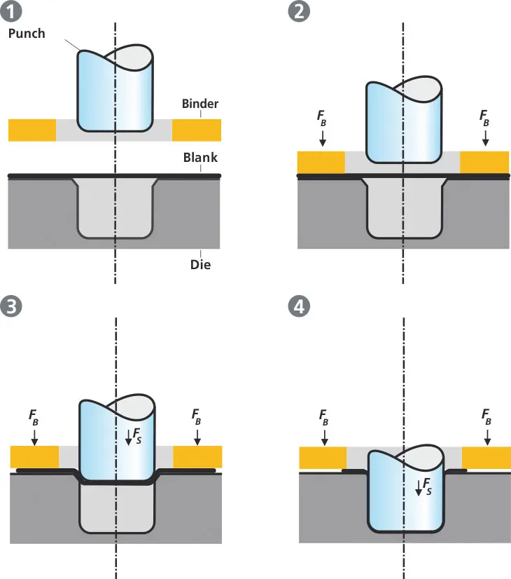
-EMBOSSING
Embossing is a metal forming process for producing raised or sunken designs or relief in sheet material by means of matched male and female roller dies, theoretically with no change in metal thickness, or by passing sheet or a strip of metal between rolls of the desired pattern.
Metal sheet is drawn through the male and female roller dies producing a pattern or design on the metal sheet. Depending on the roller dies used, different patterns can be produced on the metal sheet.
Emboss should be in 7 degree to 25 degree incline in angle and it should not be in 90 degree angle,why because when we do stamping in manufacturing the stamping tool fits the sheet metal hence it will not come out of that sheet metal,So this is the main reason why the emboss face is in angle.
Characteristics of the metal embossing process include:
- Its ability to form ductile metals,
- Its use in medium to high production runs,
- The ability to maintain the same metal thickness before and after embossing,
- The ability to produce unlimited patterns, depending on the roll dies, and
- The ability to reproduce product with no variation.

- Located within the embossing stand itself are two engraved and mated hardened steel rolls, geared together to maintain top-to-bottom pattern registration. The width and diameter of these rolls depends on the strip width, material thickness, pattern depth, and material tensile strength and hardness.
- In most machines, the upper roll blocks are stationary, while the bottom roll blocks are movable. The pressure with which the bottom roll is raised is referred to as the tonnage capacity. This figure also depends on the aforementioned parameters.
- Embossing machines are generally sized to give 2" of strip clearance on each side of an engraved embossing roll. Many embossing machines are custom-manufactured, so there are no industry-standard widths. It is not uncommon to find embossing machines in operation producing patterns less than 6' wide all the way up to machines producing patterns 70"+ wide.
- The illustration that follows provides a two-dimensional look at a typical embossing line setup with an embossing roller in the middle. The illustration shows the metal sheet entering the roller, and then the embossed sheet leaving toward the drawing rollers.
- Embossed metals are used in industry for two reasons: aesthetic and functional. Aesthetic applications also include appliance panels, building products, elevator panels, garage door panels, automotive trim, metal office furniture, and others.
- Functional applications are those in which a performance characteristic is enhanced. This can include a metal products ability to disperse liquid more effectively, reduction friction and static, increase a metal panel’s stiffness and rigidity, increase a metal surface area for acoustic or heat transfer applications, and improve traction.
- The embossing process can produce a variety of patterns. Some of the most common patterns include stucco, leather grain, wood grain, weather grain, and rough sawn cedar. Most embossers will tool to form any needed pattern, depending on the cost parameters involved.
Materials commonly used in the metal embossing process include:
- Aluminum (All Alloys)
- Aluminum (T1/T2)
- Brass
- Cold rolled steel
- Copper
- Galvanized steel
- High strength, low alloy, steel
- Hot rolled steel
- Steel (All Alloys)
- Zinc
MASTIC SEALANTS
A mastic sealant is a type of liquid sealant that cures in an elastic state, thus making it flexible while holding the bond of the surfaces that has attached together. It adheres to just about any material making an all-purpose type of sealant.
- The main purpose of the outer panel is for the aesthetic looks. Thus we cannot use bolts or welding. This has to be done with the help of the hemming and mastic sealants. Mastic sealants are elastic compound that behaves like the rubber. It is placed between the outer and inner panel. Initially is it in paste form, but after the hot furnace bath it gets hardened thus joining the outer and inner panel. Mastic sealant has the tendency to increase the strength of the panel and has influence of 80mm diameter.
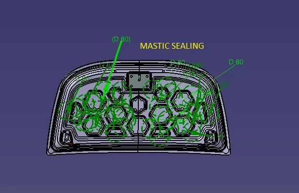
PROS
- One positive characteristic of mastic sealant is that it has a very smooth exterior while keeping its rigid form underneath.
- Surfaces do not have to be primed when using this type of sealant, and although applied thick, it adheres smoothly to any surface. It is important that the area to be joined or sealed be clean and dry, just like any other sealant on the market.
- Mastic sealant may be used outdoors as well because of its waterproof quality. It can be applied on rain duct leaks outdoors, for example.
- It is also favored for areas under high or low temperatures such as heater vents or drier vents and contains ultraviolet inhibitors to make sure that it is protected from damaging effects of the sun that will often weaken other types of sealants. That makes it a good choice for use on roofs, or any surface that is constantly exposed to sunlight. Most mastic sealants will also work well with metal because they do not corrode over time.
- it functions well in areas with mild vibration and heat, like heating ducts.
CONS
- Mastic sealant is not recommended for areas that have too much joint movement, or anything that will be moved a long length.
- It works well with constant pressure on it, but not constant movement.
- It also works best when applied thickly and is not recommended if only a thin layer is needed such as touch ups. Another sealant is a better choice for those types of repairs
HEMMING PROCESS
Hemming is a forming operation in which the edges of the sheet are folded or folded over another part in order to achieve a tight fit. Normally hemming operations are used to connect parts together, to improve the appearance of a part and to reinforce part edges. Conventional die hemming.
- Hemming is the process in which the edge is rolled flush to itself, while a seam joins the edges of two materials. Normally hemming operations are used to connect parts together, to improve the appearance of a part and to reinforce part edges. In hood design, hemming is used in assembly as a secondary operation after deep drawing, trimming and flanging operations to join two sheet metal parts (outer and inner) together. Dimensions of hemming are given below.
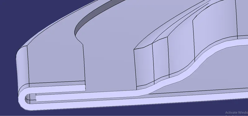
- In between the outer panel and inner panel there will be glueing after or before hemming process because to reduce NVH and also sticking the two panels.
Types of Hemming
conventional die hemming
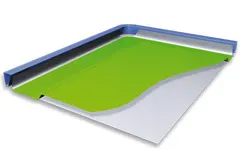
In conventional die hemming, the flange is folded over the entire length with a hemming tool.
Roll hemming
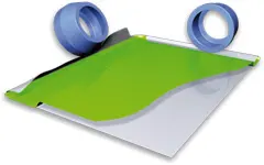
In roll hemming, the hemming roller is guided by an industrial robot to form the flange.
While manufacturing the hood we choose Roll hemming only.
RELIEF CORNER
Relief is provided onto the part or component in order to remove any stresses developed in a particular area i.e sharp corners that takes place during the hemming process is carried out. Thus corners are rounded or chamfered.
We leaving 2 mm from sheet metal for Roll hemming process.
POSITION OF STRIKER AND HINGE
For the proper opening and closing of the hood, the striker should be perpendicular to the trajectory of the hood. For this, hinge is assembled at its position. Once it is placed, hinge axis is drawn.
- To check the hinge axis as the center we draw a big circle to the position the latch in such a way that it is perpendicular to the hood trajectory.
- In between the two hinges the striker is perpendicular to the midpoint of two hinges,Why because while closing and opening of latch and striker the opening position be similar actions.
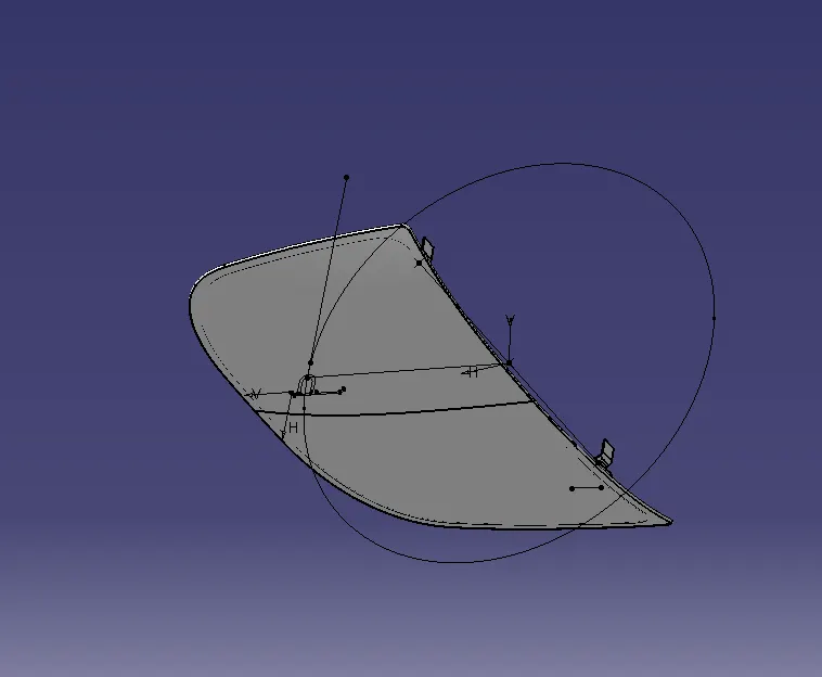
DIFFERENT VIEWS OF HOOD DESIGN
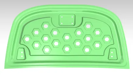
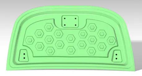
Inner hood Panel Outer&Inner hood Panel
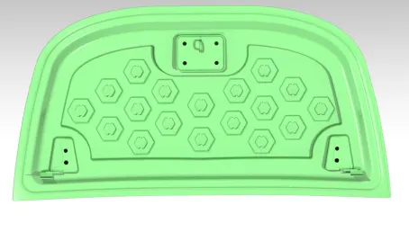
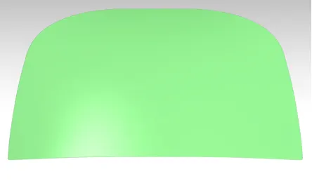
Assembly of hood ( Outer&Inner hood Panel,Hinge,Latch&Striker)
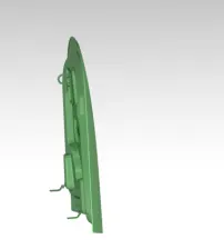
Side View Of Assembly
RENDER STYLE