Fender Design Challenge
OBJECTIVE:-
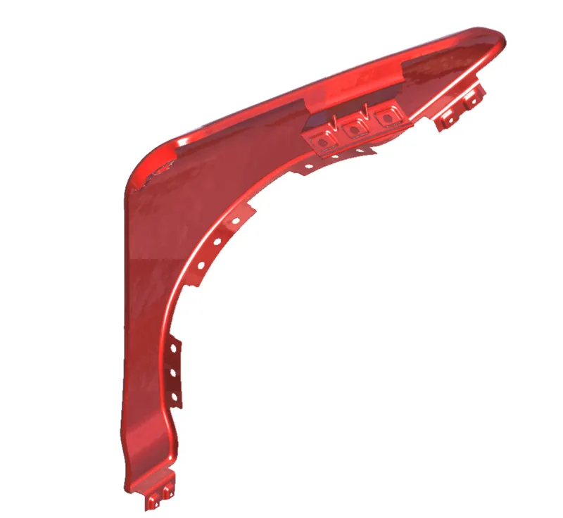
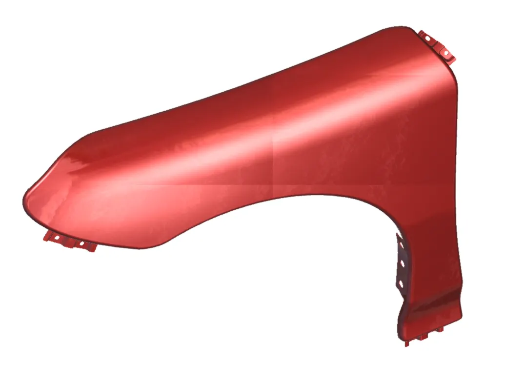
The objective of the project is to design a Body in White front Fender of a car with its mountings using the information provided by the styling team. The Skin data and Master sketch are the information provided by the styling team.
INTRODUCTION:-
-Fender is the American English term for the part of an automobile, motorcycle or other vehicle body that frames a wheel well. Its primary purpose is to prevent sand, mud, rocks, liquids, and other road spray from being thrown into the air by the rotating tire. Fenders are typically rigid and can be damaged by contact with the road surface.
-Sticky materials, such as mud, may adhere to the smooth outer tire surface, while smooth loose objects, such as stones, can become temporarily embedded in the tread grooves as the tire rolls over the ground. These materials can be ejected from the surface of the tire at high velocity as the tire imparts kinetic energy to the attached objects. For a vehicle moving forward, the top of the tire is rotating upward and forward, and can throw Objects into the air at other vehicles or pedestrians in front of the vehicle. Fender is a front outer side member of a car, which covers the wheel side. It has so many small features with ups and downs.
The Importance of Car Fenders: -
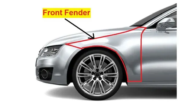
-Fenders are an intricate sheet of metal covering the wheel well of your car.
-Fenders are designed in a manner to provide resistance against wind and other roadside debris.
-When you travel on rough terrains your vehicle might get minor scratches and dents which look no better. Frequent road bumps can cause your cars paint to chip off which needs a paint job done.
-The car fenders are located on either side of the front and rear wheels. The front car fenders begin where the front door hinges run and end just before the bumper. The rear car fenders begin where the back doors close and terminate before the back bumpers.
Types of Fenders: -
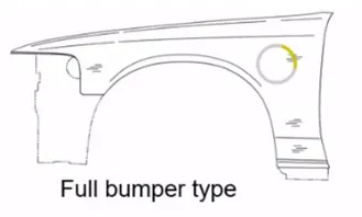
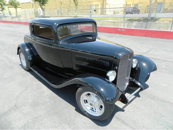
Full bumper type
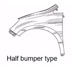
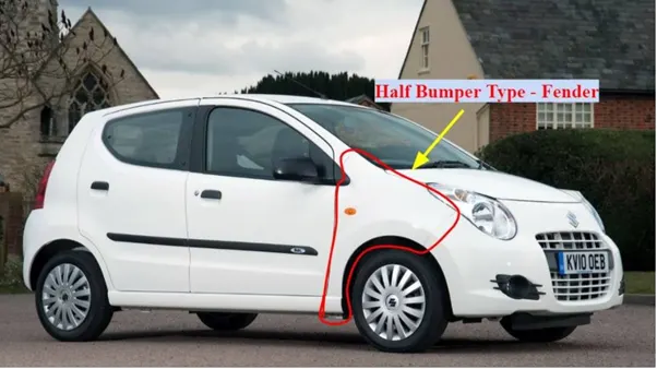
Half bumper type
FULL BUMPER TYPE: -
-Full bumper fender is not used nowadays because they required bigger size blank to produce the part & waste material is also there while manufacturing.
HALF BUMPER TYPE: -
-Half bumper fender is used because the waste of material is less & can produce two fender at the same time by slightly increase the raw sheet. and to reduce the weight & cost mostly bumper fender are been produced.
MOUNTINGS OF FENDER: -
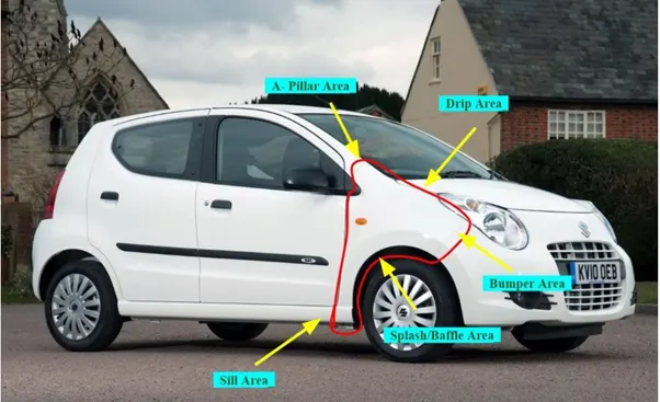
In order to fix the Fender, mountings were essential. In our design we classified these mountings in 5 areas
- Drip mountings area
- Sill mountings area
- Bumper mountings area
- A - Pillar mountings area
- Splash/Baffle mountings area
MANUFACTURING PROCESS: -
-A car Fender bumper is made by a process called reaction injection molding (RIM), which basically consists of making a special polyurethane compound and introducing it into a large fender.
-RIM is a process that conserves raw materials and reduces costs. It is similar to injection molding except thermosetting polymers are used, which requires a curing reaction to occur within the mold. Common items made via RIM include automotive bumpers, air spoilers, and fenders.
Reaction Injection Moulding: -
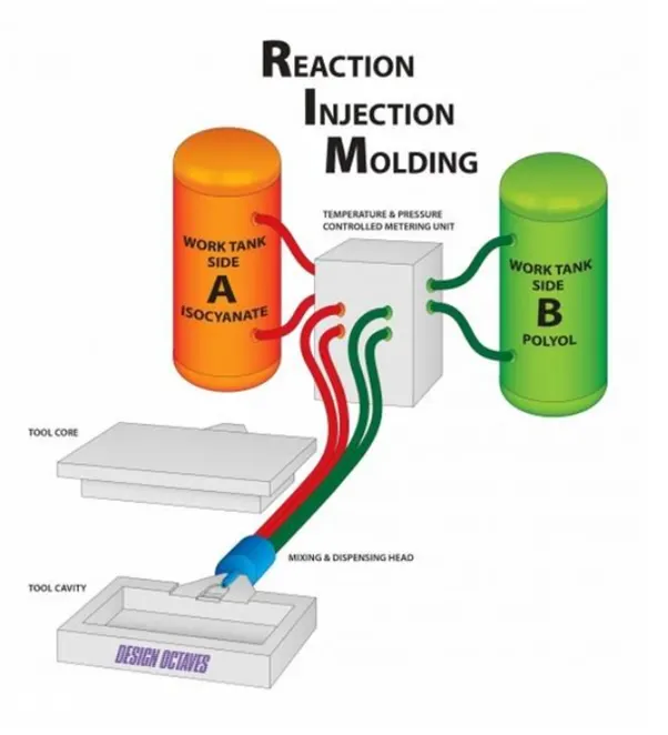
-Reaction Injection Moulding is a low pressure, low temperature process used to mould many types of plastic parts. This process is typically used for the medical, industrial and automotive industries.
-Reaction Injection Moulding (RIM) is often utilized for the moulding of strong, lightweight parts that are easily painted. The rigid materials used by Design Octaves come with a UL94V-0 rating for flammability.
-The RIM moulding material utilized by Design Octaves is a two-component system which consists of polyol and isocyanate liquids that are mixed at a high pressure and then metered into the closed tool at a low pressure. The material then expands to fill the tool and is ejected in about 5 minutes.
RIM Process: -
-The RIM process begins with polymer liquids (polyol and isocyanate) stored in storage tanks that are eventually dispensed by high-pressure industrial pumps. The polymers are recirculated from the storage tanks to a multi-stream mix-head and back to the storage tanks in a continuous loop.
-The reaction injection moulding (RIM) process utilizes low-viscosity liquid polymers. These polymers expand and thicken through a variety of chemical reactions. After the polymers have been injected into the heated mould they eventually harden. Through the RIM design process raw materials and moulding techniques can be selected, and customized, to deliver the desired weight, strength, density and hardness characteristics that you are looking for. The result is polyurethane parts with much lighter weight, and more intricate designs than those created by ordinary injection moulding.
Advantages of RIM Moulding: -
RIM moulding allows for many distinct advantages, some of which include:
-Large Parts - The properties of the liquid polyurethane components enable them to fill moulds for very large parts.
-Encapsulation of Inserts - Inserts of many types can be placed into a mould prior to injection of the RIM material. The RIM material can also encapsulate many inserts during molding.
-Thick and Thin Walls - The RIM process offers you the flexibility to design parts with significant wall thickness variations.
-Class-A Surfaces - The surface finish of parts moulded with the RIM process allows manufacturers to produce Class A painted parts.
-Low-Cost Tooling Options - The low injection pressures of the RIM process allow for tooling to be manufactured quicker, and at lower cost, than tools used in traditional injection molding, or structural foam.
Given Master section to create the Drip Area:-
PROCEDURE: -
Initially, open the model file in Catia.
Extract the edges of all the edged regions.
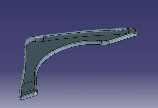
Use a parallel curve and offset it on the surface with a distance of 5mm.
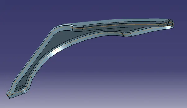
DRIP FLANG:
Create two-point on the edge of the extended surface.
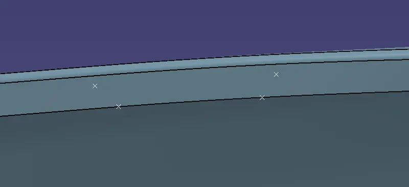
Join the parallel curve and extrude the surface along the respected direction and split it.
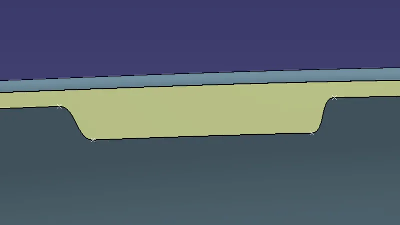
After the flang is created, create the drip area.
Create a straight line along the surface by using a point-point option.
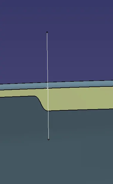
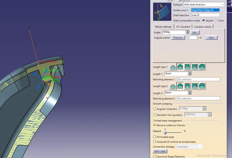
Sweep the edge to 40° using the draft direction as the line.
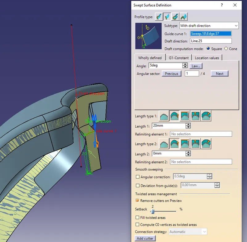
Similarly, sweep the edge to 20mm with a 5° draft direction from the line.
Again, sweep it 25mm with 90° draft direction along with the line.
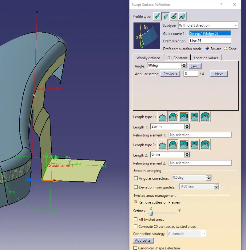
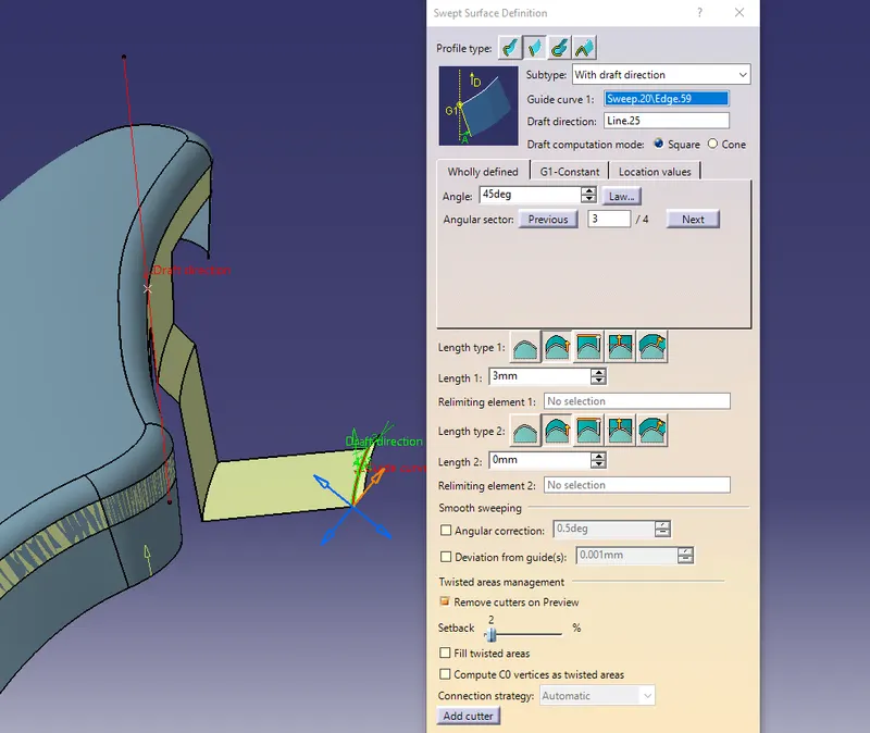
Sweep 45° with a draft direction of 3mm.
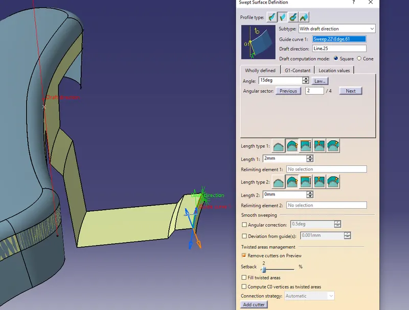
Sweep 15° with a draft direction of 2mm.
Give the shape fillets to the sweep surfaces.
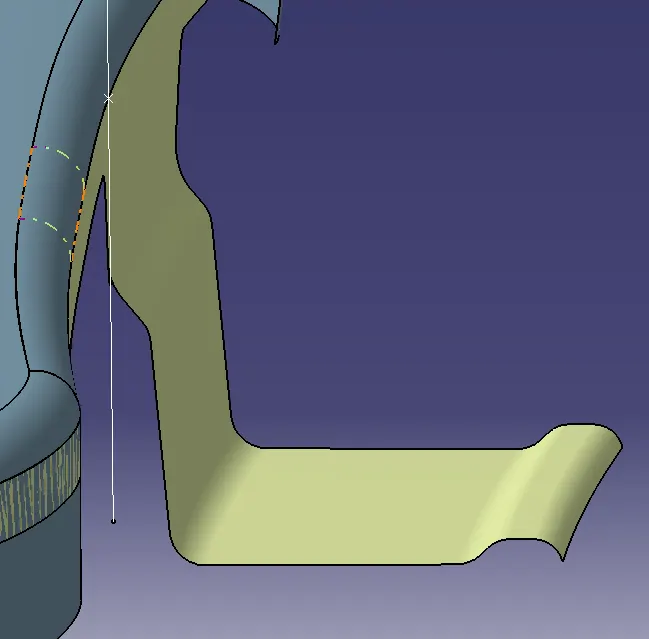
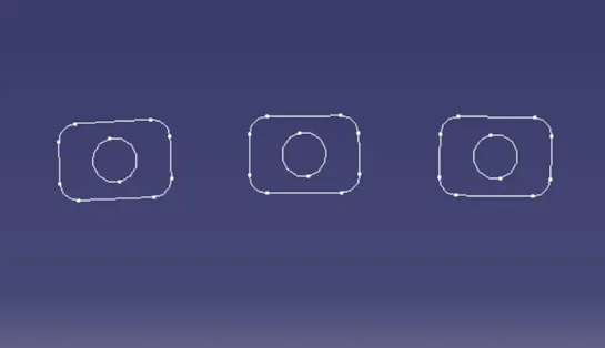
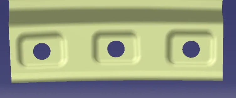
Create a sketch for embossments and project on the surface and split it.
Note: -
Design considerations for drip area:
1. 150mm Distance from the front end is kept for the headlamps in the bumper.
2. 200mm Distance from the rear end is kept for the wiper motor assembly.
3. Engine components should not be visible from the outside. For this purpose, initially, 3 degrees of angle & 9mm length is given.
4. 40 to 60mm depth is given, if the depth increases from 60mm the spring-back effect will also increase.
5. Embosses are given to the drip area to increase strength.
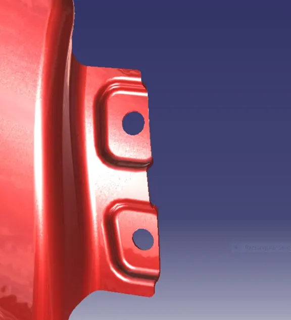
A-PILLAR FLANG: -
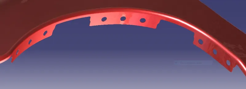
BAFFLE FLANG:-
SILL FLANG:-
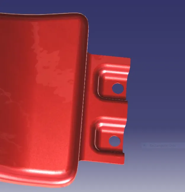
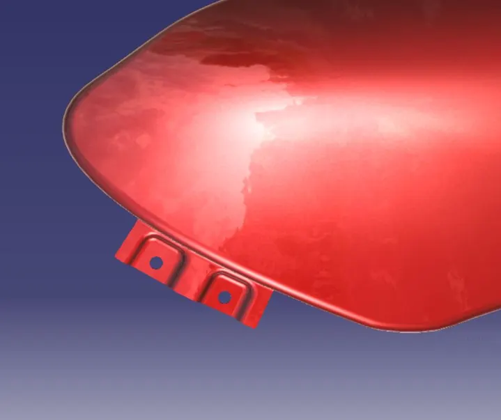
BUMPER FLANG:-
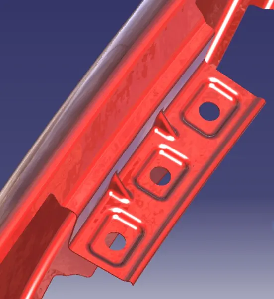
Drip Mounting Area:-
Thicken:
After the flanges are created join and thicken them to 0.75mm.