Simulink Model Of Doorbell Using Solenoid Block
Aim:-1.To Make a Simulink Model Of Doorbell Using Solenoid Block Where The Switch Is Closed For 2 Second And Then Released.& Observed The Movement Of Plunger.
- Use a Thermistor To Sense The Temperature Of a Heater & Turn On Or Turn Off The Fan As Per The Following Conditions:
Temperature Source:20C From 0to 10 Seconds, 27C From 10 To 30 Seconds, 23C From 30 To 50 Seconds
Fan Conditions: On If The Temperature Above 25C, Off Otherwise.
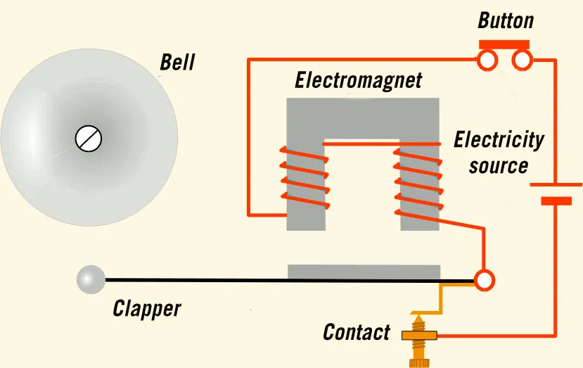
Doorbell: When We Press The Doorbell,This Will Complete a Circuit That Allows Electricity To Flow Through The Doorbell’s Internal Electromagnet. The Magnetic Field Generated By The Electromagnet Is Then Used To Power a Mechanism That Creates The Doorbell Sound. Doorbell Are Low-Voltage Devices.
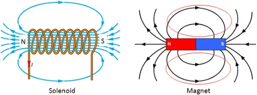
- Solenoid:-A Solenoid Is a Device Comprised Of a Coil Of Wire, The Housing And a Moveable Plunger (Armature). When An Electrical Current Is Introduced, a Magnetic Field Forms Around The Coil Which Draws The Plunger In. More Simply, a Solenoid Converts Electrical Energy Into Mechanical Work.
Procedure:-
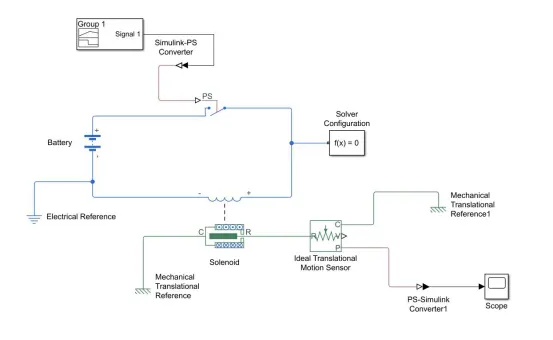
- When The Switch Is Closed The Signal From The Signal Builder Is Transfer To The Circuit By The Simulink-Ps Convertor.
- The Battery Which Supply Electric Current To The Circuit And The Solenoid Start Behaving Like An Electromagnet.
- And The Behaviour Of Electromagnet Is Sense By The Ideal Translational Rotational Sensor & Its Further Transfer The Signal To The Scope Which Recorded The Behaviour Of Circuit In The Form Of Plot.
Doorbell Using Solenoid Block
Blocks Which Is Used In Doorbell Circuit
- Signal Builder:-Create And Generate Interchangeable Groups Of Signals Whose Waveforms Are Piecewise Linear.
- Simulink-Ps Converter:-ConvertSimulink Input Signal Into Physical Signal.
- Switch:-Switch Controlled By External Physical Signal.
- Solver Configration:-Physical Networks Environment And Solver Configuration.
- Electrical Reference:-Connection To Electrical Ground.
- Solenoid:-Electrical Characteristics And Generated Force Of Solenoid.
Mechanical Translational Reference:-Reference Connection For Mechanical TranslationalPorts - Ideal Translational Motion Sensor:-Motion Sensor In Mechanical Translational Systems.
- Ps-Simulink Converter:-Convert Physical Signal IntoSimulink Output Signal.
- Scope:-Display Signals Generated During Simulation.
Result:-
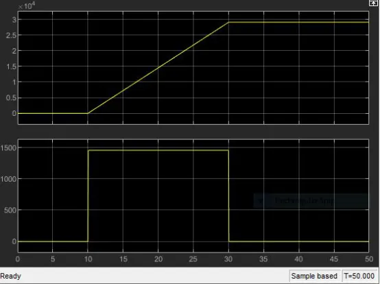
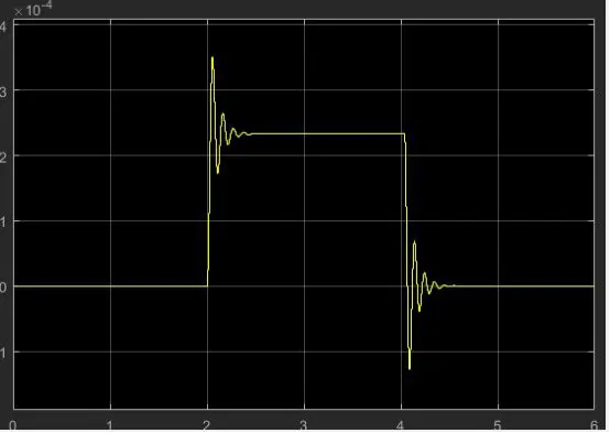
- The Switch Is Closed For 2 Second And Then Released.We Will Record The Value With The Help Of Scope Block.But There Is Flactuation Is The Signal Which Is Shown In The Graph
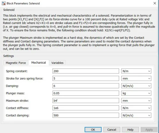
But The Flactuation Of The Signal Is Removed By Increasing The Value Of Damping
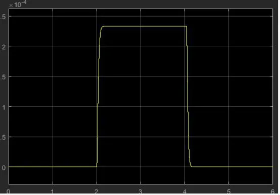
- After Increasing The Value Of Damping We Will Get Plot Like This
2.Use a Thermistor To Sense The Temperature Of a Heater & Turn On Or Turn Off The Fan As Per The Given Conditions
Thermistor:-
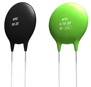
- A Termistor Is a Heat Sensing Resistor. They Convert Heat Energy Into Electrical Current.
- Most Thermistor Have -Ve Temperature Coefficient Of Resistance.
- Thermistors Are Made By Heating Under High Pressure Semiconductor Ceramics Made From Mixture Of Metallic Oxides Of Managenese, Nickel, Cobolt, Copper, Iron Etc.
- These Are Pressed Into Desired Shape And Then Baked At High Temparature.
Procedure:-
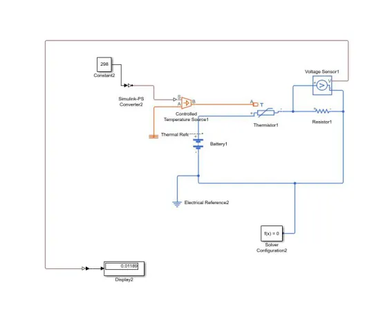
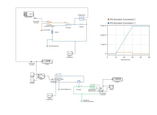
- Ther Signal From The Signal Builder Is Transfer To The Control Temperature Source With The Help Of Simulink-Ps Source.
- The Controled Temperature Source Is Store The Signal In The Form Of Temperature.And Transfer It To Thermistor .
- Which Sense The Temperature Signal And Convert It In To A Electrical Signal Which Is Detected By The Voltmeter And Voltmeter Is Connected Parallel To The Resistance.
- And The Signal From The Voltmeter Is Transfer To The Switch And The Switch Is Work On The Bases Of Given Conditions.
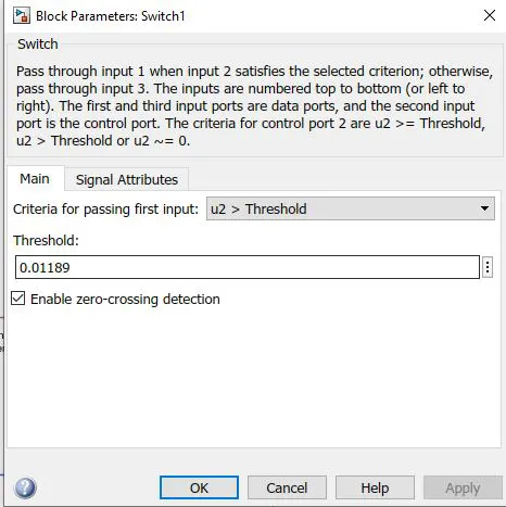
- The Throushold Voltage Which Is Given To The Switch Is Calculated On The Bases Of Temperature 298k
- If The Switch Is On Then The Signal Is Transfer To The Current Voltage Source
Through This Signal Is Transfer To Dc Motor. Or Dc Motor Transfer The Signal To The Ideal Rotational Motion Sensor.
Blocks Which Is Used In Circuit
- Signal Builder:-Create And Generate Interchangeable Groups Of Signals Whose Waveforms Are Piecewise Linear.
- Simulink-Ps Converter:-ConvertSimulink Input Signal Into Physical Signal.
- Controlled Temperature Source :-Variable Source Of Thermal Energy, Characterized By Temperature
- Thermistor:-Negative Temperature Coefficient Thermistor Using B-Parameter Equation
- Switch:-Switch Controlled By External Physical Signal.
- Solver Configration:-Physical Networks Environment And Solver Configuration.
- Electrical Reference:-Connection To Electrical Ground.
- Mechanical Translational Reference:-Reference Connection For Mechanical TranslationalPorts
- Ps-Simulink Converter:-Convert Physical Signal IntoSimulink Output Signal.
- Controlled Voltage Source:-Ideal Voltage Source Driven By Input Signal
- Dc Motor:-Dc Motor Model With Electrical And Torque Characteristics And Fault Modeling.
- Scope:-Display Signals Generated During Simulation.
- Dashboard Scope:-Trace Signals During Simulation
Result:-
The Plot Shows That The Angular Velocity(w) And Angular Displacement.(A) Of The Ideal Rotational Motion Sensor(Fan) or On the bases of given conditions.