Week 1:- Introduction to BiW and Fixtures Challenge
1.What is BIW & define its parts ?
In Automotive industries, BIW (body in white) is the common terminology used to describe the sheet metal welded structure. This structure is married with other components like engine, Transmission system and trims are joined. The name is derived based on the appearance of the structure which has grayish-white color before it is painted.
In today’s situation, automotive BIW is made of various grades of steel, and a few high-end luxury cars are made up of aluminum alloy. The image below illustrates an automotive BIW.
There are two major ways to build an Automobile
- Unibody ( Monocoque )
- Body on Frame
Unibody ( Monocoque )
The term monocoque is frequently misapplied to unibody cars. Commercial car bodies are almost never true monocoques but instead use the unibody system

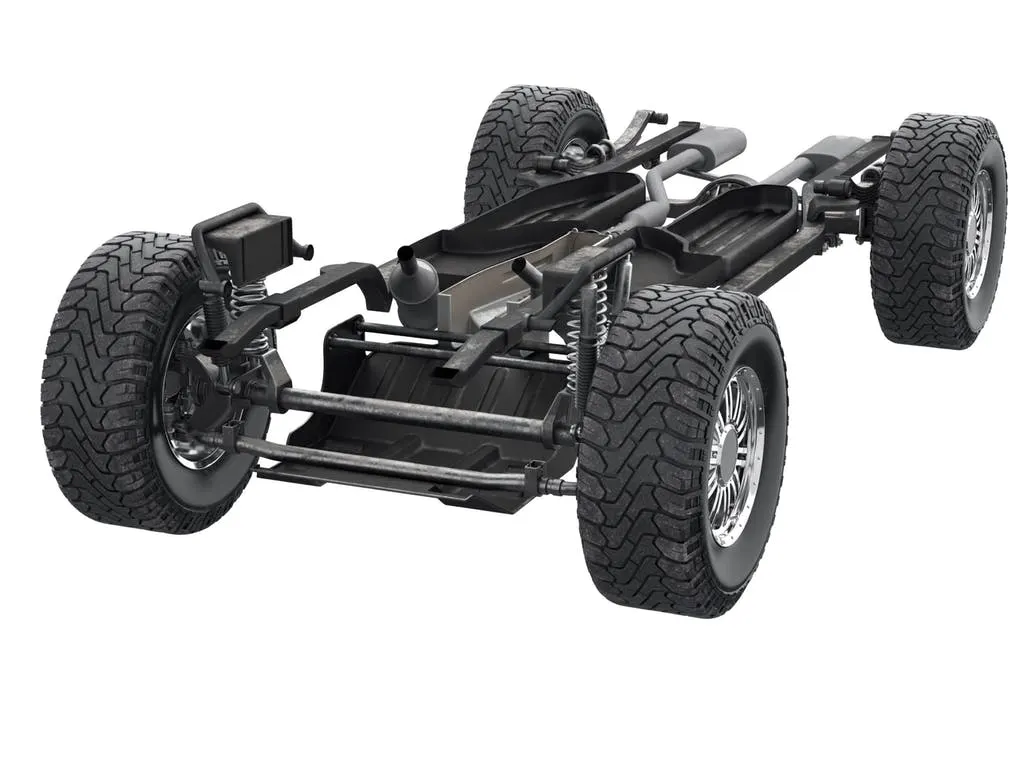
Body on Frame :
Body-on-Frame: The vehicle’s structure has two basic parts: the body and the frame. The body – the basic “skeleton” of the vehicle that forms the cabin, engine bay, and cargo area – sits on top of a strong, flat frame, which supports the weight of the vehicle and holds the suspension and wheels.
BIW parts are divided as follows :
- Underbody structure
- Front End structure
- Body side structure
- Closure
- Roof
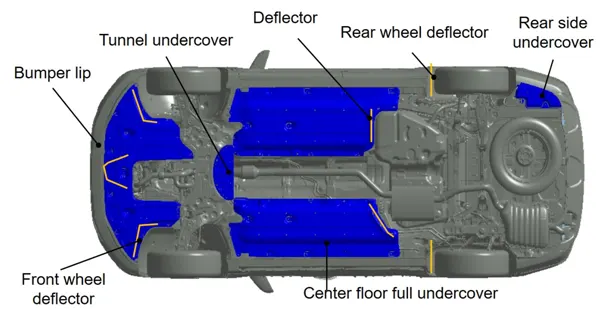
Underbody structure :
An automobile underbody structure includes a floor panel having a pair of longitudinal side edges, each extending longitudinally of the automobile body structure and having a respective side sill rigidly secured from below to the associated side edge so as to extend in a direction generally parallel to the longitudinal dimension of the automobile body structure.
Body side structure
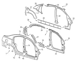
In a vehicle body side structure, a tailor welded blank is used for forming an outer panel assembly consisting of a frame structure, and a center pillar assembly is connected vertically between a roof side rail and a side sill outer of the outer panel assembly.
Closure :
As in the BIW, a side closures, and door is manufactured through process, such as blanking, rolling, stamping and assembly. The analyse the influence of tolerances and visualization on the side closures are classified into three major categories
- Hinge Adjustments.
- Striker Adjustments.
- Hemming Technology.
Roof :
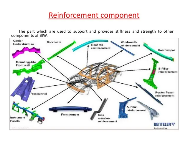
A Roof Bow is a sheet metal part, usually spot welded to the BIW inner frame, forming the inner structure of the vehicle body. Its primary function is to supporting.
2.what do you understand by biw nomenclature?
Nomenclature is basically choosing of names for things. BIW have no. of parts in it. All parts have differenent names.
- The names of different parts of Biw are as shown in the Figure given below
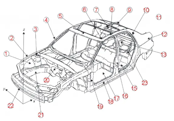
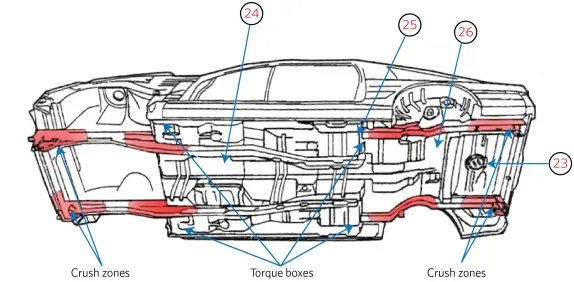
PARTS NAME ACCORDING TO THE NUMBERING
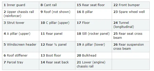
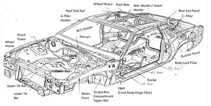
3.What is fixture & its types ?
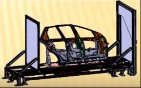
Fixtures are the work holding device, which holds, supports, and locates the workpiece. Welding fixtures are generally used in the automotive industry to hold various BIW components together in order to be welded. It is necessary to ensure that there is minimum or negligible distortion in the workpiece during the welding process. Locating elements are placed to ensure the repeatability of the assembly is the same. The clamping of the workpiece should be lighter such that it does not damage the panels and the clamping areas must be clear of the welding area.
Below are the general types of fixtures
1.Production Fixture- It is used for mass production purposes in the automotive industries, these are the fixtures where all the car panels are assembled together for the final outcome. The dimensional and tolerance are checked whether the quality is met or not. The maintenance of the fixture must be feasible for regular checks.
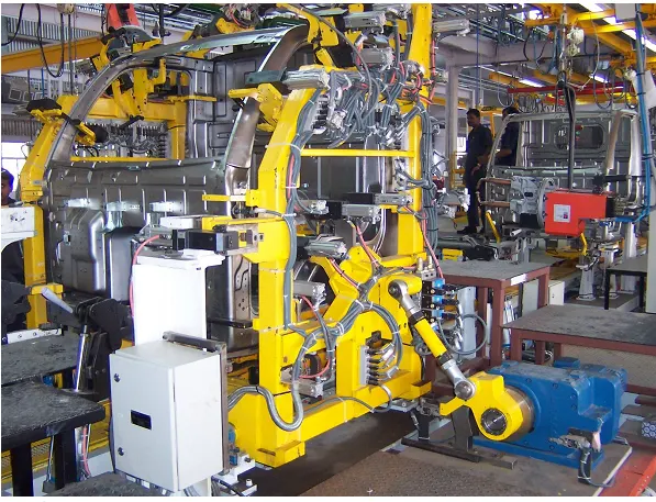
2.Preproduction Operation Fixture- It is used as a prototype fixture to study the feasibility of the initial batch production and to make any type of changes to the production fixture. The cycle time of the pre-production fixture is higher than that of the production fixture and there is a huge involvement of the manual operators and engineers during the process. Most of the automotive industries prefer production fixtures over the pre-production fixture in order to save more time and cost as this cost would have a direct impact on the final cost of the car.
3.Checking Fixture- it is the fixture used for checking and inspecting an assembly. These are similar to geo fixtures but no operations are done like welding and gluing. Instead, these fixtures use internal or external gauges to check for dimensional accuracy, Geometric accuracy, and tolerance with respect to the CAD data provided by the engineer.
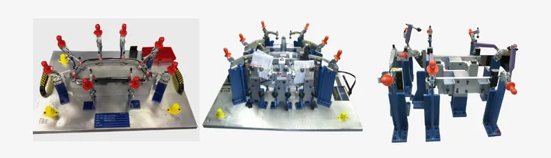
4.What is the basic principle of fixture design ?
The main purpose of the fixture design is to hold the workpiece such that it does not move or distort during the process. It is very important to properly locate the work piece in the fixture.
For any free body, there will be 12 degrees of freedom as shown in the image below
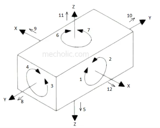
6 translational degrees of freedom: +X, -X, +Y, -Y, +Z, -Z
And 6 rotational degrees of freedom:
- Clockwise around X-axis (CROT-X)
- Anticlockwise around X-axis (ACROT-X)
- Clockwise around the Y-axis (CROT-Y)
- Anticlockwise around the Y-axis (ACROT-Y)
- Clockwise around Z-axis (CROT-Z)
- Anticlockwise around Z-axis (ACROT-Z)
It is required to fix all the 12 degrees of freedom except the three transitional degrees of freedom (-X, -Y, and -Z) in order to locate the workpiece in the fixture. So, 9 degrees of freedom of the workpiece need to be fixed by using the 3-2-1 method as shown below:
- Rest the workpiece on three non-collinear points of the bottom surface (XY), and you will be able to fix the +Z, CROT-X, ACROT-X, CROT-Y, and ACROT-Y degrees of freedom
- Now, rest the workpiece at two points of the side surface (XZ), and you will be able to fix the +Y and ACROT-Z degrees of freedom.
- Now, rest the workpiece at one point of the adjacent surface (YZ), and you will be able to fix the +X and CROT-Z degrees of freedom.
In this way, the 9 required degrees of freedom are fixed by using the 3-2-1 principle of fixture design.
5.Elaborate types of BIW Stations ?
The BIW assembly line is where different types of panels are joined together in each specified zone like Underbody zone, Hood zone Etc.
These zones are further subdivided into stations, where various processes like welding gluing and inspection are done to the part of that particular zone before they are being assembled together. For instance, in the roof zone, various reinforcement is to be added before they are married to the side zone.
BIW Stations are classified into four parts as below
- Tools
- Grippers
- Stands
- Miscellaneous
- TOOLS
A tool is a fixture that consists of a number of units to hold a car panel. there are four types of tools as follows
- Geo Tool
- Re spot Tool
- Marriage Tool
- Framer Tool
- Checking Tool
1.Geo Tool
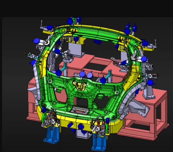
- In Geo fixture, welding is done for all the parts to be assembled in that fixture.
- The geometry of the pattern is defined accurately in the geo fixture.
- These fixtures have a tight accuracy standard
- All the machine parts individually should be made with max tolerance of ± 0.02 mm. whereas the positional accuracy of the pin should be within ± 0.1.
- To maintain the cycle time of the assembly line the welding in the geo tool fixtures is done in such a way that there would not be any distortion in the accuracy of the assembly and the remaining welding is done in re spot tool.
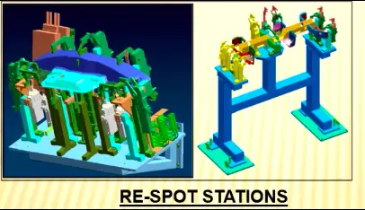
2.Re spot tool
A Re-spot tool is a fixture where remaining welding which is not done by the geo tool, is being completed.
In case, of re-spot Fixture, the tolerance value can vary up to +_ 1.0 mm. In general,-0.28mm.
These loose tolerances are due to the fact that they are not forming the geometry of the assembly. Which is already defined in the geo tool fixture.
3.Marriage or Hemming Tool
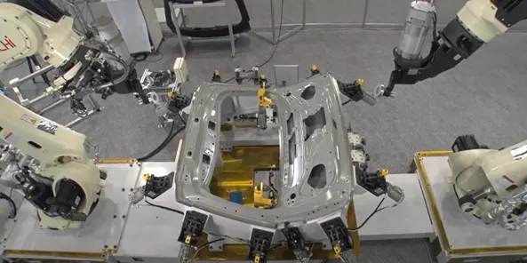
The marriage or hemming tool fixture is used to join the inner panel assembly and the outer panel assembly is joined together.
This process is usually done by hemming and using mastic sealants such that it does not affect the aesthetics of the car.
Hood, Side doors, and tailgate are assembled in this way.
4.Framer Tool
The framer tool is the next stage of the marriage tool.
The part from the marriage tool is fixed with the roof panel.
5.Checking Tool
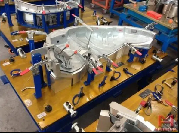
- A Checking station is a fixture that is used for the checking of the assemblies of the components.
- The Checking fixture can be gauge type, fixed type, and automated checking fixture.
- It generally checks for the geometrical accuracy and tolerance of the assembled part coming out of the geo tool fixture. It does so by comparing the measured value with that of the data from the CAD.
- GRIPPERS
A gripper is a fixture which holds the car panel, these fixtures are generally the end effectors of a robotic arm. It is important to keep the weight of the gripper as light as possible because they have to be mounted on a robot.The types of grippers are as follows
- Material Handling Gripper
- Process Gripper
- Combo Gripper
- Dual Gripper
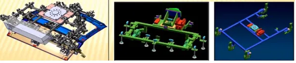
1.Material Handling Gripper
- The material handling grippers are generally used to move the car panels from one tool station to another.
- Most of the material handling grippers are vacuum grippers in the automotive industry.
2.Process Grippers
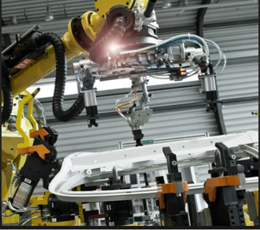
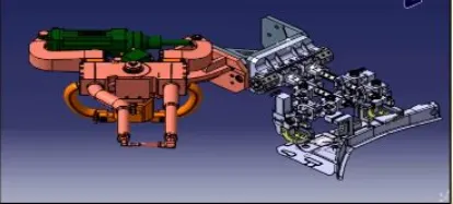
- This type of grippers is used to carry out a process like welding and gluing in the car panels. The grippers take the panel to the pedestal welding or gluing stands where these processes are carried out.
- After the processes are done the gripper takes the panel to another station and drops it there for further processes.
3.Combo Gripper
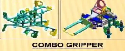
- Combo grippers are designed to handle the car panel from one station to another.
- Along with it, it has a welding gun at another side of the gripper in order to perform the welding operation.
4.Dual Gripper
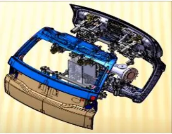
Dual grippers are also designed to handle the car panel from one working station to another working station.
The grippers will be on both sides.
It is capable of handling two panels at a time. These grippers are mostly used when symmetrical car panels are being married like the side doors.
- STANDS
Stands are used to hold the panel when not in use like weld gun, glue gun. The Stands are fixed with the shop floor to maintain accuracy. The types of stands are as follows.
- Pedestal Stands
- Gluing and Sealer Stands
- Docking stands
- Date Stamp Stand
- Pedestal Stand
The weld gun will be mounted on the stand which is fixed with the shop floor. The process gripper will take the panel under this pedestal welding stand and perform the welding operation.
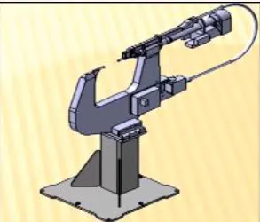
2.Gluing or Sealing Stand
Gluing or sealing gun is fixed to a welded or a standard stand that is grounded to the floor permanently.

3.Docking stand
If the robots are assigned with multi-tasking like material handling and welding it cannot do the tasks simultaneously as the robots have restrictions to the payload and also for space constraints, it uses the docking stands.
One process is done it drops the gripper in the docking stand and picks up the gun for another process.
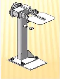
4.Date Stamp Stand
The date stamping device will be mounted on this stand to emboss the date on the car panel.
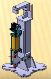
- MISCELLANEOUS
- Curing
- Buffer Stand / Storage
- Conveyors
- Takeout Trolleys
- Conveyors
1.Curing
Once the gluing process is done it needs to be cooled. Hence, the panels are put on the conveyor, so that it cools down until it reaches the next station.
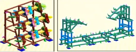
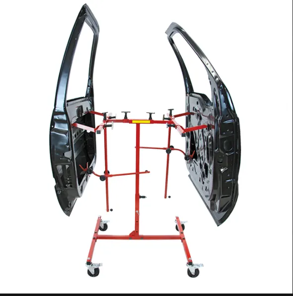
2.Buffer Stand
The buffer stands are provided with the section so that number of assemblies can be
These assemblies are then stored or moved from one station to another.
The assemblies stored can be used when there is maintenance work going on any stations to avoid the stoppage of the whole assembly line
3.Conveyor
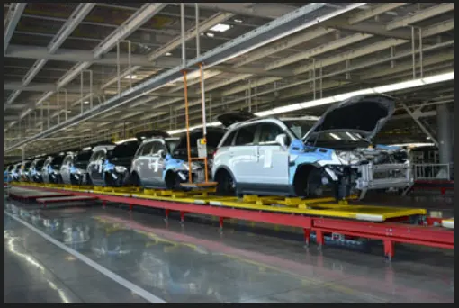
- The conveyor is used to move the panels from one station to another station
- They can be of belt type and chain drive.
- The panels are kept in the pallet or fixture fixed on a rotating belt and are moved
4.Take out Trolleys
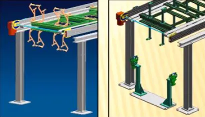
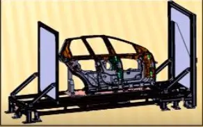
- Take out trolley is used to take the car panel out of the robotic working station between the cycle for inspection purpose
6.What are the basic terminologies used in the BIW fixture
The basic terminologies used in the BIW fixtures are
- NC/mylars/Fingers
- PLP( principle locating points)
- Blade
- Raiser
- Shims
- Rough Locators
- Hard wares
- CMM
- Units
- Number plates
- Co-Ordinate plate
- Nameplate
- Clamp Arm
- Pivot
- Class A Surface or Skin Surface
- Reed Switches
- Sensors.
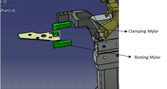
1.Mylar/NC/Fingers
- Mylars are the part which holds the panel from above and below during the operation.
- The top side of Mylar is called the clamping Mylar. Whereas, the bottom side Mylar is known as resting Mylar.
- Every Clamping Mylar will have a resting Mylar.
- It holds the panel in such a way that it does not deform during the welding process.
- The below image shows basic Clamping and Resting Mylar.
2.PLP(Principle Locating Points)
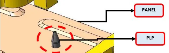
Principle locating points are those where we use pins for locating the panels. These points help in maintaining the geometrical accuracy of the panel.
3.Blade
- Blades are plates that are attached to the raiser.
- The cylinders and other additional arms are mounted on a Blade.
4.Raiser
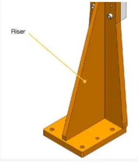
- A raiser is a part that is used to raise the height of the fixture.
- The raiser is fixed to the base of the fixture and the blade is mounted on the raiser
- There are two types of raisers 1.L type raiser 2.Square Tube raisers.
5.Shims
Shims are small parts of the thickness of 0.1,0.2,0.3 mm. The shims are used to compensate for the difference due to the stack-up tolerance of the assembly, which eventually results in the improper holding of the panel if the Mylar holds it loosely. One the other hand if the Mylar holds the panel very tightly then it will form an impression in the panel. Shims play a major role by adjusting the Mylar to the defined position.
6.Rough locators
Rough locators are majorly used in manual fixtures. The rough locators will guide the operators to place the part in the correct position and orientation.
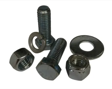
7. Hardware
Hard wares are the fasteners that are used like the bolt, nuts, washers, Self-locking Nuts, etc.
8.CMM
CMM is known as a coordinate measuring machine. CMM is used to check the coordinates of a fixture, measure the assembly, and compares the data with the CAD design.
9.Units
The fixture is the assembly of different units. Some of the units used in fixture assembly are the Base unit, Pin unit, Clamp unit, etc.
10.Number Plate
The number plate is the aluminum embossing on each unit for the recognition of the units.
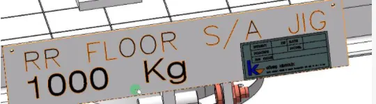
11.Name Plate
The details like manufacturing company name, fixture type, Fixture weight, etc are embossed on the plate and joined to the fixture.
12.Clamp Arm
The clamp arm is the part of the clamping unit which will hold clamping Mylar and will rotate over an axis.
13.Pivot
It is an axis about which the clamp arm will rotate.
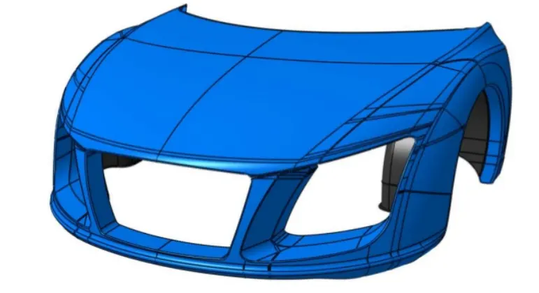
14.Class A Surface or Skin Surface.
The outer panel of the BIW which adds styling and aesthetics to the car is known as the Class A surface or Skin Surface. It is important that while assembling these surfaces in the fixture there must not be any damage done to it. So , while designing we should make sure that the clamping material is soft which would not dent the surface. In this case, Nylon and PU material is used for Clamping.
15.Sensors are Reed Switches
These are the electrical components that are used in the automated fixtures for their smooth operation. Sensors are placed in a fixture to make sure that the operator has placed all the parts in the correct position. Reed Switches are used to determine the position of the piston inside the cylinder which would enable the operator to see whether the clamping is on or not.