Photo Realistic Rendering
DESIGN ASSEMBLY AND RENDERING OF AMERICAN CHOPPER MOTORCYCLE USING SOLIDWORKS
Objective: The project's main aim is to learn the essential tools, commands, and part modelling of the customized American chopper bike using Solidworks Photorealistic rendering assembly using photo view 360 and solid works visualize for understanding the mechanical design process.
Introduction:-
American Chopper
American Chopper bike was started in 2003, located at Orange county choppers company, New York, the U.S. It was the most popular motorcycle at the time. These bikes have a high rake angle and trails, low seat height and low ground clearance, long wheelbase, and long front suspension travel. The rider seat with the upper torso upright and leaning slightly rearward. The footpegs are in such a position that the rider has to extend their legs forward. Handlebars tend to be high and wide. The emphasis is on comfort while compromising corning ability because of low ground clearance and greater likelihood of scraping the footpegs, floorboard, and other parts; if a turn is taken at speed, other motorcycles can readily be accompanied.
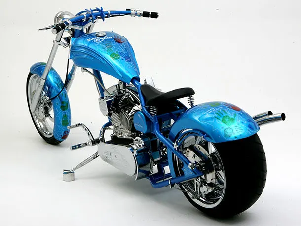
Fig: - Example of American Chopper bike
Design Tool: - Solidworks
Solidworks is a 3D modelling computer-aided design and computer-aided engineering application published by Dassault Systems, founded in December 1993.
Solidworks is structured in three basic types:-
- Part mode
- Assembly mode
- Drawing mode
- Part mode is the very first and primary mode of Solidworks in which a 3D model is created. To create any design, we have to sketch from the sketching environment. First, we need to select the sketching plane to start a sketch for the base feature. The three default planes are provided: the Front plane, Top plane, and right plane. ( file format:-.SLDPRT)
- In Assembly mode, the Assembly is created by assembling the component designed earlier in the part mode to form a complete model. We can also make the model by creating parts in assembly mode. Assembly is produced by mating relations between parts. These relations are termed Mate tools. ( File format:-.SADLSM)
- Drawing mode is used for the detailing of any created part or Assembly. This model does all the detailing or documentation in a 2D format. The documentation consists of different drawing views and the details in the drawing views. We can describe all the views by dragging and dropping parts or assemblies that we created in part mode or assembly mode. (File format:-.SLDDRW)
Design methodology:-
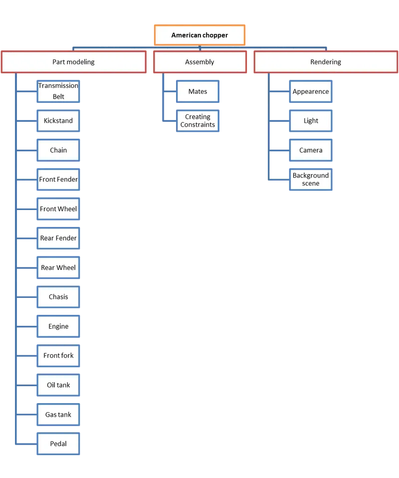
List of Commands with their Explanations:-
Sketch commands:-
- Line: - Used to draw a sketch (midpoint line, construction line..)
- Arc: - Arcs are created by positioning points.
- Smart dimension: - we can easily give dimensions to any sketch using this command.
- Ellipse:- Used to draw elliptical shapes in sketch
- Circle: - The circle is another important sketching tool that enables us to create circulars. There are two types of circles available Centre circle and the Parameter circle.
- Properties: - This tool enables us to define relations between different sketches in required situations.
- Offset is used to copy sketch entities to a specified distance from the original entity.
- Slots: - There are four types of slots about the centre axis by adding dimension, straight slot, and centre point straight slot.
- Rectangle: - Use to draw different types of rectangles.
- Trim: - It is used to delete excess unrequired geometry.
- Extend: - This tool extends the entities to nearby geometry based on the required selection.
- Spline: - Splines are two or three-dimensional curves defined by a set of control points.
- Mirror:- Used to create a reflected copy of the desired entities about a plane/axis/centerline.
- Pattern: - This tool is used to pattern the sketch entities either horizontally, vertically, angled, or in a circular path. (Linear pattern, Circular pattern).
- Convert Entities: - It is used to copy model edges into an active sketch.
Feature Commands:-
- Extrude: - This tool is used to develop a 3D environment with the reference of a 2D sketch.
- Revolve: - This feature tool is used to create a solid feature by revolving about an axis, and it is mainly used to create a cylindrical pipe or solid body which an axis.
- Loft: - It is used to create a solid by connecting two profiles with the reference of the guide curve.
- Extrude cut: - This tool is used to remove a section from a 3d body as per the area defined in a 2D sketch.
- Pattern: - In the feature tab, this tool also has a similar feature used to pattern bodies.
- Shell: - This tool is used to create hollows out apart. It can be performed in two ways one by selecting a face that creates a hollow body that leaves the selected face open and creates a thin-walled surface as a boundary to the remaining faces, and another by without any selection which creates a hollow solid body with the desired thickness.
- Fillet: - This tool is used to round the internal or external edge of a part by giving the desired radius.
- Chamfer: - Similar to that fillet, this tool is also used to remove sharp edges, but it creates sloping edges. We can define a chamfer with angle – distance or distance-distance method.
- Dome: - This tool is used by selecting planar or non-planar faces and used to calculate the radius of the arc as a basis for a dome.
- Split: - This feature is to create multiple parts from the existing part. With the use of this tool, we can split solid bodies and surface bodies.
- Combine: - This tool is used to add two or more bodies, get a common area between two bodies, or subtract two bodies from each other.
- Mirror: - This tool is used to create a reflected copy of selected bodies along a selected plane/axis.
- Curves: - Project curves are used to select bi-directional to create a projection that extends at both sides of the sketch.
A composite Curve is used to combine curves, sketch geometry, and model edges into a single curve.
- Reference geometry: - It defines the shape or form of the solid or surface. It includes planes, axis coordinate systems, and points.
- Swept Boss: - It is used to sweep a sketch along a path, and it must be a non-self-intersecting boundary and closed.
- Draft: - It is used to taper faces using a specified angle, selecting faces of the model.
- Surface knit: - It is like combining the body used to fill the gaps between surfaces and get surfaces to combine.
DESCRIPTION:-
Solid modelling of all the parts of the American chopper and the sketches used as well as its features are explained below:-
- Transmission Belt: Transmission Belt is a mechanical component used to transmit the power from one shaft/ pulley or a rotating component to another. These belts are made mostly with rubber materials having a long life and low maintenance cost. Here transmission belt is used to drive the chain shaft driven by the engine flywheel.
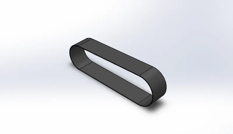
Sketch command used:-
- Line
- Arc
- Smart dimension
- Properties
- Offset entities
Features command used:-
- Plane
- Extrude
- Fillet
- Appearance
Procedure:-
- Select the front plane and sketch the transmission belt using a line and 3 point arc.
- Dimension them line 350mm and two arcs 70 and 60 mm respectively.
- Select all sketches and offset them 3.5 mm inward.
- close the sketch and extrude it for the blind condition of 88mm
- Fillet 1mm to all the edges.
- Change the appearance of the part to rubber mate
- Save the part as TRANSMISSION BELT.
Link of the part: - https://drive.google.com/file/d/1yKE3O3til7vnTpbCQhhj-3M5-0Jp_hEV/view
- Kickstand: It is one of the important components that carry the whole body of the vehicle without falling on the ground during rest position. The function of the kickstand is to manage the amount of load to keep the bike at an incline position on which a load applies for the stability of the bike to keep it untouched.
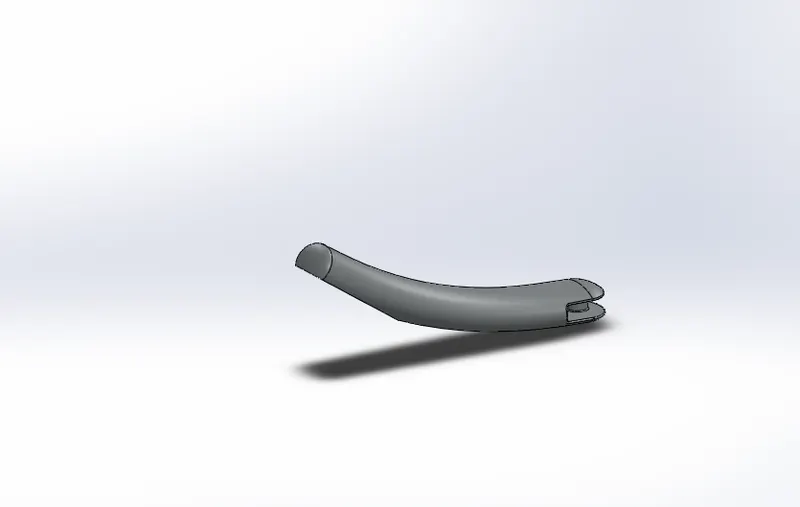
Sketch command used:
- Line
- Spline
- Ellipse
- Circle
- Smart dimension
Feature command used:
- Loft
- Extrude
- Cut Extrude
- Fillet
- Split
- Dome
- Appearance
Procedure:-.
- Draw an ellipse on the front plane
- Draw a spline from the origin as per dimensions 130mm horizontally and 40mm vertically from the origin.
- Take a reference plane at the endpoint of the spline.
- Another spline is drawn on the reference plane.
- The dimension of the bigger ellipse is 40mm horizontally and 18mm vertically, and the smaller one has 30mm and 20mm dimensions, respectively.
- Create a loft by selecting both the ellipse.
- Create a 13mm and 5 mm dome at the face of both the bigger and smaller elliptical faces.
- Sketch a rectangle of 28 mm horizontal and 8 mm vertical dimensions at the right plane.
- Use extrude cut tool with 50mm dimension through the midline.
- A flat face at the bottom of the kickstand is created by drawing the line at the reference plane and using the split tool.
- A pivot point is created at the bigger end, making a circle of 9mm diameter at the upper face of the extruded cut part.
- Lastly, fillet all edges of 2mm and .5 mm.
- Change the appearance of the entire part to a chromium plate.
Link of the part: - https://drive.google.com/file/d/1yPjxbkxcfuMYYAyYzt6yESUnrmeMpn0Q/view
- Front Fender: It is like a protective part of the front wheel that can protect us from substances like mud or spray of water that come along with moving wheel during riding.
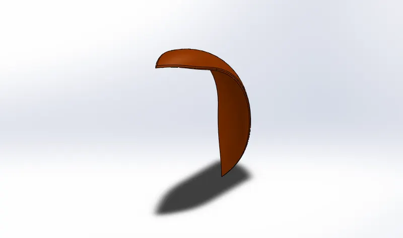
Sketch command used:
- Line
- Arc
- Smart dimension
- Offset
- Trim Entities
- Extend Entities
- Splines
Feature command used:
- Axis
- Revolve
- Fillet
- Split
Procedure:-
- Draw a 3 point arc of radius 125mm on the vertical plane.
- Give width of the arc is 160mm and the upward distance from the origin is 280mm.
- Offset the arc 6mm inward.
- Close the sketch using extend and trim entities.
- Draw a construction line at the origin.
- Revolve the sketch in direction one, 5 degrees, and in direction two, 130 degrees.
- Draw two splines on the top plane with the given dimension.
- Similarly, on the other end of the fender and split both the end.
- Fillet all the edges at a 6mm radius.
- Change the appearance of the entire part to painted Siena.
Link of the part: - https://drive.google.com/file/d/1yRc6N5Nl2ul2HroA059w6hsC2GdtGTBQ/view
- Rear Fender: The function of the rear fender is similar to that front fender except for the width because of the width of the rear wheel.
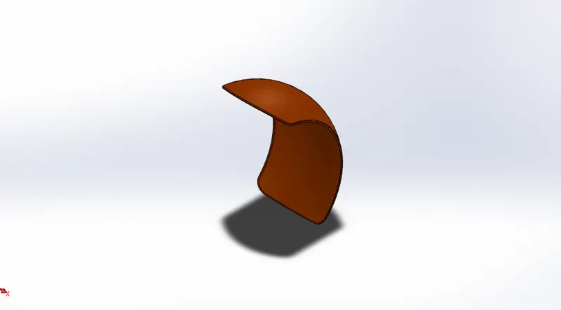
Sketch command used:
- Line
- Arc
- Smart dimension
- Offset
- Trim Entities
- Extend Entities
- Splines
Feature Command used:
- Axis
- Revolve
- Fillet
- Split
- Shell
Procedure:-
- Draw a 3 point arc of radius 290 mm on the vertical plane.
- Give width of the arc is 364mm and the upward distance from the origin and centre point of the arc is 90 mm.
- Offset the arc 6mm inward.
- Close the sketch using extend and trim entities.
- Draw a construction line at the origin.
- Revolve the sketch in direction one, 10 degrees and in direction two, 140 degrees.
- Draw another 3 point arc at the top/centre plane with a radius of 265mm and a distance from the centre of the arc and origin is 227mm.
- Use a split toot to remove the edges to get the desired shape.
- Fillet the corner edges with a radius of 45mm and the remaining edges with a 4mm radius.
- Select the inside face and use the shell tool with a 4mm dimension
- Change the appearance of the entire part to painted Siena.
Link of the part https://drive.google.com/drive/folders/1AGMrHvBYZ-KbqsbRaWBc4nzvaay7f231
- Oil tank: Oil tank in an American chopper is used to store the oil for lubrication and cooling purpose of engine components. The oil tank is located right below the rider's seat and above the engine's gearbox.
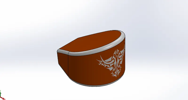
Sketch Command used:
- Line
- Spline
- Properties
Feature Command used:
- Extrude
- Combine
- Fillet
- Shell
- Appearance
Procedure:-
- Select the top plane and sketch given and dimensioned them.
- Extrude the sketch 170mm in direction 1 and 10mm in direction 2.
- Select midline and draw another sketch of the given dimension as shown in the picture.
- Extrude this sketch using the Through-all option.
- Go to insert > feature > combine tool and select common in operation type.
- Fillet all the edges with a 10mm radius.
- Lastly, use the shell tool and set the parameter to 3mm.
- Change the appearance of the part to painted Siena.
Link of the part: https://docs.google.com/document/d/11SSTL_fn7-inbXfeBpfXda9lNHaV3oDq/edit?usp=sharing&ouid=105256797472360938165&rtpof=true&sd=true
- Chain: A chain is a set of several links made of small plates and pins connected in a loop to transmit mechanical energy to the rear wheel. The main use of the chain is to transmit power from one shaft to another using sprocket as a connecting means to the shaft. It has a high power transmission capacity, good flexibility and low cost. The smaller diameter side of the chain is aligned with the engine gear, and the larger diameter of the chain is aligned with the rear wheel gear, which is the driven gear.
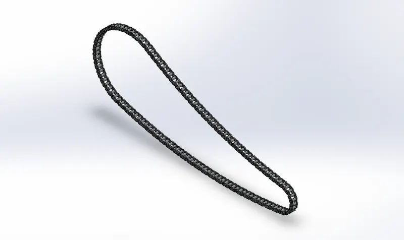
Sketch command used:
- Circle
- Line
- Arc
- Trim
- Smart dimension
- Properties
Feature command used:
- Extrude
- Blocks
- Curve driven pattern
- Fillet
- Mirror
- Appearance
Procedure:
- Select the midplane and draw the given sketch, and dimension them.
- Draw inner and outer plates of the chain and save them using add block as chain link one and chain link 2.
- Now insert Chain link one from the block tool and make the circle's centre point concentric about the path sketch.
- Similarly, insert chain-link two and make it concentric with one of the circles of chain-link one and one with the path curve.
- Now extrude the circles first using select contour at midplane 25mm.
- Select the sketch again, extrude only the outer plate, choosing offset 5mm outwards, and blind it by 2mm.
- Similarly, again choose the inner plate to extrude and this time, use from vertex option and select the inner point of the outer plate and blind it 2mm.
- Now fillet the outer faces of both the pins with a radius of 0.5mm.
- Now go to curve-driven pattern, select the path as direction, select bodies to pattern, and select all the bodies, with a spacing of 30.26mm and the number of instances 20.
- Now again, insert chain link one and chain-link two concentric it to the path sketch and repeat the same process until it forms the close loop, selects all the pins, and saves them in the folder Pins.
- At the last pins or meeting point of the last plate and first plate, if there is a gap between pin and plate, delete the respective plate and draw a new plane on the midplane between them.
- Lastly, mirror all the bodies according to the midplane and change the appearance of the part to a Chromium plate.
Link of the part: https://drive.google.com/file/d/1v1mXY0vwx2zlJKKY0MRPIGgKB8xscTTm/view?usp=sharing
- Pedal: A pedal is a component the raider uses to place their foot while riding the bike. Apart from that, it also helps in applying breaks and shifting the gear.
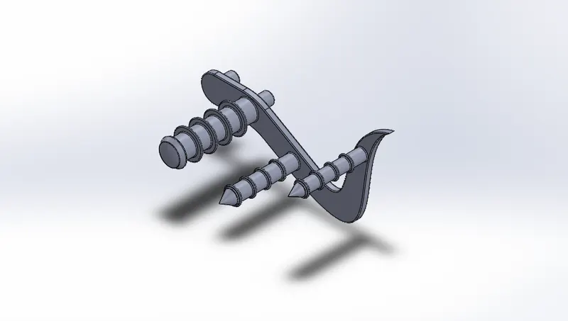
Sketch command used:
- Line
- Circle
- Spline
- Fillet
- Smart dimension
- Properties
Feature Command used:
- Extrude
- Fillet
- Chamfer
- Dome
- Linear pattern
- Revolve
Procedure:-
- Draw the sketch on the front plane.
- Use extrude tool to extrude the sketch in an 8mm direction
- Again select sketch one, extrude the circles 20mm and reverse the direction.
- Apply 1mm fillet to the edges of the first extrude part.
- Draw the given sketch on the top plane. And revolve the part.
- Apply 3mm Dome to the face of revolve part.
- Apply 1mm fillet to all the edges of the revolving part.
- Select sketch one again and extrude both smaller circles from the face to 100mm
- Apply chamfer of 16mm and 7.70 mm distance to distance to the edge of both extruded circles.
- Draw three circles on the face from the centre of all three circles with an offset of 2.5mm.
- Extrude this with the offset of 20mm and direction of 2.5mm
- Apply 1mm fillet to all the edges.
- Now apply linear pattern 20mm in direction 1 with 4 number of instances selecting extrude and fillet feature.
- Apply 1mm fillet to the remaining edges.
- Lastly, change the appearance to a chromium plate.
Link of the part: https://drive.google.com/file/d/13G0gmJC890E3cM--K8sDZricsDAF0YAw/view?usp=sharing
- Rear-wheel:
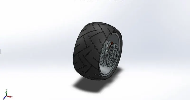
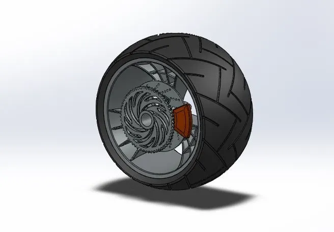
Sketch command used:
- Line
- Arc
- Circle
- Spline
- Offset
- Trim
- Fillet
- Convert entities
- Mirror
- Smart dimension
- Properties
Feature command used:
- Extrude
- Cut Extrude
- Revolve
- Linear pattern
- Combine
- Fillet
- Revolve cut
- Chamfer
Rim: Rim is the outer edge of the wheel that holds the tire. It is an important part as it ensures proper fitting of the tire and rotates around the axis.
Procedure:
- Draw the sketch on the front plane and give their dimension.
- Revolve the sketch.
- Select the right plane and sketch as shown in fig.
- Extrude the sketch at the midplane and give 200mm dimension.
- Again use convert entities to offset it 9mm and draw two splines as shown in the picture.
- Cut extrude the part using through all options.
- Now select Bodies to pattern and change the number of instances to 3.
- Now use combined tools to combine all bodies.
- Select the front plane and draw the given sketch
- Now cut revolve to 360 degrees.
- Apply 3 mm fillet to both the faces.
- Select the Right plane and draw a circle of 60mm at the origin.
- Cut extrude the sketch 200mm at the midplane.
- Draw the sketch at the front plane as given.
- Revolve the sketch.
Rotor: It is the circular disc connected Caliperwheel. When the calliper squeezes the brake pads together, then the surface area creates friction.
Procedure:
- Draw a circle at the right plane with a diameter of 320mm.
- Draw a sketch on the face of the extruded part and take the circle as the given dimension and use a linear pattern.
- Again draw a sketch and cut extrude the part.
- Apply a 5mm fillet to the corner edges of the cut part.
- Use circular pattern with 9 number of instances selecting cut extruded and fillet part.
Calliper: Inside a calliper, there is a pair of metal plates called brake pads. TCaliper use of the calliper is to slow down the bike wheel by creating friction with help of brake pads.
Procedure:
- Draw the given sketch on the right plane.
- Use extrude tool at the midplane with the offset of 3.5mm and 30mm blind.
- Apply chamfer distance to distance option D1 20mm and D2 Caliperface of the calliper.
- Again apply chamfer on another face but using D1 6mm and D2 20mm.
- Apply 4 mm fillet to side edges and 8mm fillet to corner edges.
Tire: strong and flexible rubber casing that is attached to the rim of the wheel give external protection to the rim. Tires ate generally made of rubber to ensure flexibility and bump absorption.
The tire contains threads that provide grip to the road.
Procedure:
- Draw the given sketch on the front plane, and revolve it along the axis.
- Draw the given sketch and dimension it accordingly.
- Cut extrude the sketch at 0ffset of 400mm and select offset from the surface by selecting the face of the revolving part to 6mm.
- Check the Reverse offset and translate the surface box.
- Use circular patter at 9 number of instances.
Sprocket: It is a chain wheel having teeth around its circular pattern, the chain attached to the sprocket help drive the wheel using power transmitted by the engine.
Procedure:
- Draw a 300mm circle at the right plane, and use convert entities to convert a smaller circle as shown in the picture.
- Extrude it to 50mm.
- Apply 4mm 45degree chamfer it the edges.
- Select the face of the sprocket and draw as shown.
- Cut extrude using up to next option.
- Apply 2.20mm fillet at the edges.
- And pattern this feature with 60 number of instances.
- Again select the face of the sprocket and draw the below sketch.
- Cut extrude to 10mm.
- Similarly, draw another sketch as shown below and also cut extrude it to 10mm.
- Apply 1mm filled to the edges.
- And Circular patter these to 7 number of instances.
- Lastly, change the appearances of the parts
- Rim- chromium plate
- Tire - Mate rubber
- Calliper – Painted sienna
- Sprocket- chromium plate
- Rotor- chromium plate
Link of the part:- https://drive.google.com/file/d/1HNwfFycHS-xNySQPMsjJLFf2HNhW0lx2/view?usp=sharing
- Front-wheel
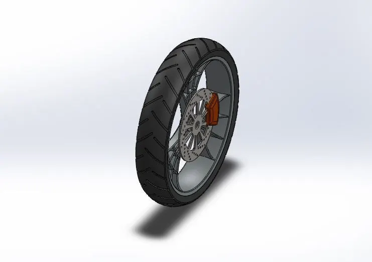
Sketch command used:
- 3-Point arc
- Lines
- Splines
- Mid-point line
- Circle
- Sketch fillet
- Trim
- Extend
- 3-point centre rectangles
Features command used:
- Revolve boss/base
- Extrude boss/base
- Extrude cut
- Revolve Cut
- Circular Pattern
- Combine
- Fillet
- Chamfer
- Appearance
RIM: It is an outer edge of a wheel that holds the tire on the wheel. The main function of the rim is to support and seal the tire to the wheel. It ensures proper fitting between tire and rim. Rims are important parts as they rotate around rods that are called axles.
Procedure:
- Select the front plane and draw a sketch as shown in the picture below and give dimensions accordingly.
- Revolve the sketch along the horizontal line at the origin.
- Draw another sketch at the right plane and sketch as given.
- Use extrude tool to extrude the sketch 122mm blind.
- Draw another sketch at the right plane as shown.
- Select the midplane and draw the sketch using convert entities and offset tools and give dimension.
- Boss extrude the sketch using up to vertex option.
- Select the front plane and make ketch given.
- Cut revolve the part.
- Select cut revolves and makes circular pattern at 3 number of instances.
- Go to insert > Feature> combine and add all the bodies.
- Apply 4mm fillet to both the faces.
ROTOR: It is a circular disc that is connected to each wheel. These are designed to turn kinetic energy into thermal energy. When the callipers squeeze the brake pads together then the surface area creates friction.
Procedure:
- Select the right plane and draw a circle of 345mm at the origin.
- Extrude it with the offset of 45mm and 7mm blind in direction 1.
- Select the face of the rotor and sketch as shown.
- Cut extrude the part using up to next option.
- Make the circular pattern of the cut part at 14 number of instances.
- Again draw the sketch on the same face and dimension it as shown below.
- Extrude cut the sketch using up to next option and apply a 5mm fillet to the corner edges.
- Again use a circular pattern to the cut extruded part at 10 number of instances.
- Make a 40 mm circle at the right plane. And cut extrude it at midline using through all.
CALIPER: The job of callipers is to slow down the bike wheels by creating friction with the brake calliper inside each Caliper there is a pair of metal plates known as brake pads.
Procedure:
- Select the Right plane and sketch as shown below.
- Extrude it 19.5 in direction1 and 10.5 in distance 2.
- Apply distance it distances chamfer 6mm in direction 1 and 20 mm in direction 2 Caliperface of the calliper.
- Apply 8mm fillet to the corner edges and 4 mm to the remaining side edges.
TYRE: Tire is external protection of rim which touches the ground. It is a strong and flexible rubber casing that is attached to the rim of a wheel. Natural rubber is a material used for manufacturing tires.
Procedure:
- Select the front plane and sketch as shown.
- Use revolve tool to revolve the sketch along a circular path.
- Again select the front plane and sketch.
- Cut extrude the sketch at 450m offset and 4mm offset from the surface.
- Apply fillet to all the edges.
- Use circular pattern at 14 number of instances selecting features.
- Lastly change the appearance of the bodies:-
Tire - Mate rubber
Calliper - Painted sienna
Rim - Chromium plate
Rotor - Carbon steel
Link of the part: https://drive.google.com/file/d/1JAv3xxXqOvOn-DX7Gjx_htp4krU5xF8B/view?usp=sharing
- Front Fork It is a part of the bike that holds the front wheel. It consists of two blades which are joined together at the top by a fork crown. It works like the front suspension on the motorcycle. It absorbs shocks which has springs on it due to this can feel comfortable during travelling on uneven roads. It has good benefits during riding on speed breakers, so it is better to have a front fork.
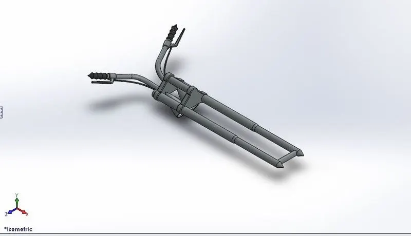
Sketch command used:
- Lines
- Spline
- Circle
- Properties
- Convert Entities
- Trim
Feature command used
- Revolve Boss
- Extrude Boss
- Fillet
- Revolve
- Linear Pattern
- Extrude Cut
- Dome
- Revolve Cut
- Sweep
- Mirror
- Combine
- Planes
- Appearance
Procedure:
- Draw the given sketch on the front plane and revolve the sketch by using revolve tool by selecting the axis.
- Draw the required sketch on the top end of revolve part and extrude it 20mm.
- Fillet all the edges.
- Again draw a circle at end of the shaft and extrude it.
- Draw another sketch using a spline and line tool on the front plane and dimensioned them accordingly.
- Revolve the sketch and create an offset of 4mm at the face of the revolving part to cut extrude the part.
- Apply a 3mm fillet on the edges of revolve sketch.
- Create a dome of 7mm and apply a fillet to the edges.
- Draw sketches to create a projected curve for the brake wire and a circle at the end apply constraints and use swept tool.
- Use mirror tool selecting midplane as a reference and combine to respective parts and at last give their respective appearances to them.
Link of the part: https://drive.google.com/file/d/1NY0IRsNCqaWbkAomPK3VgzTQjGbw7e-6/view?usp=sharing
- Chassis It is alike a metal frame that forms a skeleton for mounting components on it. All components like Engine, suspension, fuel tanks and seats etc. are attached to this base. On basis of different bikes usage of materials also can change. Some of the materials like steel, titanium and magnesium with requirements like cost, stiffness and speed are used.

Sketch command used:
- Splines
- Circles
- Lines
- Sketch picture
- Arc
Feature command used:
- Sweep
- Mirror
- Boss Extrude
- Chamfer
- Fillet
- Extrude cut
- Dome
- Plane
- Split
- Combine
- Revolve
- Curves
- Appearance
Procedure:
- Select the required plane and insert the picture using the sketch picture command and give the appropriate position to the pic as given.
- Draw two sketches to create a projected curve and create a circle of a given direction and apply swept feature.
- Mirror the part selecting midplane as a reference.
- At the end of the mirror, part draws the desired sketch and extrude it a used cut extrude it cut the desired shape.
- Require fillets and chamfer are added to these plates. A plane is then created to the profile which connects the rear wheel.
- At the inside of this axle, a circle is drawn and extruded to insert the wheel and the dome is applied to the end.
- Splines are drawn on the front plane with a good profile along with the chassis in the picture. Then concentric Circles are drawn by using swept Tool material is added along this path like structure to form for chassis.
- By using a split tool some of the portions that enter into plates are removed by using a profile of plate and cut profile of tubes from the axle.
- Similarly, all required structures are drawn by using circle profiles and splines that connect with this circle. Then swept boss is selected to follow the profile on the path.
- All the required parts are drawn by using respective tools and at last appearance of the required material is given to the chassis.
Link of the part: https://drive.google.com/file/d/1NCurP8laA0GVAacv-EPTXKURuicar65O/view?usp=sharing
- Engine: It is a machine used to change chemical energy into heat energy and heat into mechanical energy. And rotate the wheel of the bike to provide motion. Some of the main parts included in the Engine are piston, Camshaft, flywheel, crankshaft and connecting rods.
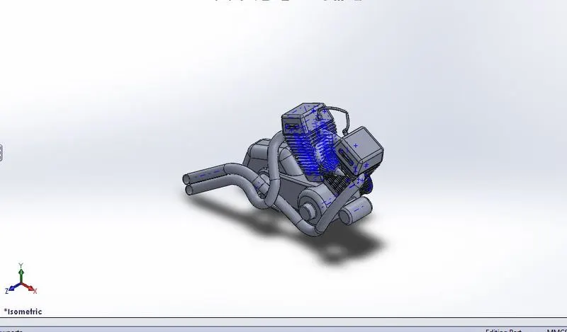
Sketch Commands used:
- Sketch picture
- Circles
- Splines
- Lines
- Properties
- Arc
Feature Commands used
- Boss Extrude
- Fillet
- Revolve
- Plane
- Circular pattern
- Dome
- Extrude Cut
- Chamfer
- Fillet
- Sweep
- Mirror
- Combine
- Curves
- Split
Procedure:
- Insert the sketch picture selecting a suitable sketch, circles are drawn at the required positions based on the blueprint and joined by lines.
- Apply to extrude tool to extrude the sketch, again desired sketch is drawn and extruded.
- Again sketches are drawn with the reference of the blueprint and revolve it to get the desired shape.
- Revolve the sketch and make extruded rectangles on the pulley for the grip element for the belt, using a circular pattern.
- Make circular pattern holes on pulley face and apply dome
- Do similar operations for the rear pulley.
- Sketch for starter motor with the picture reference and extrude it appropriately.
- Sketch for cylinder casing using reference plane.
- Sketch a rectangle on the plane and extrude it as per sketch reference.
- Provide fins using linear pattern and fillet as required.
- Create spark plugs and provide fillets.
- Mirror across the right plane to create a second cylinder casing.
- Create mounts on the bottom for the chassis mounts.
- Sketch Ø40mm at sprocket reference from the picture.
- Extrude the sketch 80mm and sketch the sprocket circle and extrude a further 15mm.
- Provide chamfer, chain cuts as done with the rear sprocket.
- Provide chamfer to the sprocket shaft as given.
- Use spline following the sketch picture and create projected curves.
- Sketch a line to cut out the exhaust ends using split.
- Use splines and projected curves for the air intake manifold.
- Sketch the air filter and revolve it and provide cuts using extrude cuts.
- Use splines and sweep them with circles for the spark plug cables.
- Provide polished Aluminum appearance to the engine and gloss black to spark plugs and the cables and save the part as the engine.
Link of the part: https://drive.google.com/file/d/1pI2lJulKIbvFgwkO4q6T06wxWE-LtDwv/view?usp=sharing
- Gas tank: It is a safe container for storing flammable fluids. It is usually placed above the engine and indirect to sunlight, so they are susceptible to fuel expanding with heat which pushes more fuel. It is designed as such so it enhances the look of the bike.
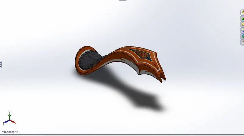
Sketch Commands used:
- Lines
- Splines
- Sketch picture
- Convert Entities
- Offset
- Arc
- Trim
Feature Commands used:
- Planes
- Mirror
- Sweep Cut
- Shell
Surface Commands used:
- Sweep surface
- Trim Surface
- Surface Loft
- Projected Curve
- Boundary surface
- Knit
- Split Line
- Extrude Surface
- Fillet
Procedure:
- Rename the Front, Top and Right planes to the midplane, bottom plane and Right plane respectively.
- Insert sketch picture to the midplane and place it accordingly and use appropriate transparency.
- Select the midplane and draw the given sketch.
- Create a new reference plane using the front plane on the starting point of the sketch.
- Create appropriate splines on the new plane using the reference of the blueprint.
- In the surface tab use sweep in direction of the midplane.
- Sketch splines on the Bottom plane using the picture reference.
- Create projected curves, new planes and sketch as in the reference picture.
- Use surface loft for the new sketches.
- Use boundary surfaces and appropriate relations to create the surface model of the fuel tank.
- Create a sketch for the seat on the bottom plane.
- Use surface extrude for the seat and provide appropriate fillets.
- Knit all surfaces and make them solid.
- Create a shell of 3mm without any selection.
- Give appearance to seat as beige cotton fabric and the fuel tank as painted car blue.
- Save the part.
Link of the part: https://drive.google.com/file/d/1GN-aS5jYhhvLujIa19p7npeUHYKINp-H/view?usp=sharing
Assembly of American chopper
The designed model is inserted into the assembly profile using an insert part option in Solidworks. The mate features are used to assign the relation between the parts modelled which are parallel, coincide, concentric, perpendicular, fix, etc. relations which assign the parts to their proper position and make a complete assembled American Chopper Bike. Once the Assembly of the bike is completed, the decals are provided to the respective parts using photoview360.
Commands used during Assembly:
- Insert components
- Mates
- Mirror components
Procedure:
- Initially, all required parts are selected and opened for assembling. The new file is opened by selecting Assembly. Then all required parts to be assembled gets opened.
- Then we use the insert component option to open the required part. At first, the chassis is selected and placed by choosing the required position.
- After that Engine is opened and placed manually at the required position.
- The front plane of the chassis and engine are selected and mates are applied to be coincident.
- Again both the bases of chassis and Engine are selected and made a coincident relation.
- The front foot face of the engine and face of the chassis plate is selected and made a distance relationship. Then it gets fully defined.
- Then both mid planes are selected to form coincident relation.
- Then pedal is opened the respective face of the pedal and chassis is selected to form concentric relation.
- In the same way, other faces of respective parts are mates to concentric.
- Then the surface of the pedal and the surface of the chassis is selected to form coincident relation.
- And at last, the pedal is mirrored to get the same part on another side of the chassis.
- The kickstand is opened and placed at the required location then inside the respective surface of the kickstand and the surface of and chassis is selected and made a concentric relation using mates.
- Again the face of the kickstand and chassis is selected and made a concentric relation.
- The required angle is applied to rotate it to stand it in the required position.
- Lastly, planes are selected and made to coincide.
- The transmission belt is selected and placed at the required position. The inside edge of the belt and the circle at the required face of the engine is selected to form concentric relation.
- By using the advanced mate option with width selection required components are selected to assemble properly. Then based on the adjacent surface certain angle is assigned for the belt.
- Then oil tank is opened and placed in a certain position. The bottom portion of the tank and top portion engine is selected to form coincident relation.
- Then required planes are selected to form coincident relations.
- The rear wheel is selected then it is rotated about the required axis for proper position and placed at the required position.
- The inside hole of the wheel and axle is selected to form concentric relations. Then required planes of chassis and wheel are selected to apply a coincident relation.
- Then rear fender is selected then it is placed above the rear wheel. On basis of required planes coincident relation is applied.
- The chain is selected and placed above the edge of the rear wheel.
- The midplane of the chain and chassis are selected to form coincident relation. On basis of width selection sprockets and chains are selected for proper Assembly.
- The gas tank is selected and placed at the proper position then all the required planes for both Gas tank and chassis are selected for applying coincident relation.
- Then front fork is selected and placed at the required position. The width option is chosen and selected Gas tank and fork locations to apply the advanced mate.
- The front wheel is selected and placed beyond the front fork. The whole wheel and axle of the front fork are selected to form concentric relations. Then required planes of both parts are selected and coincident relation is given between them.
- The front fender is selected and rotated at required positions then placed above the front wheel. On basis of the required mid planes of both the parts are selected to form a coincident relation to get a proper assembly of American chopper.
- Decals are applied to the respective parts of the chopper.
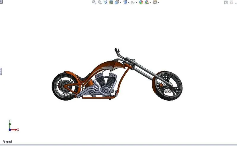
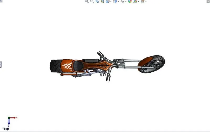
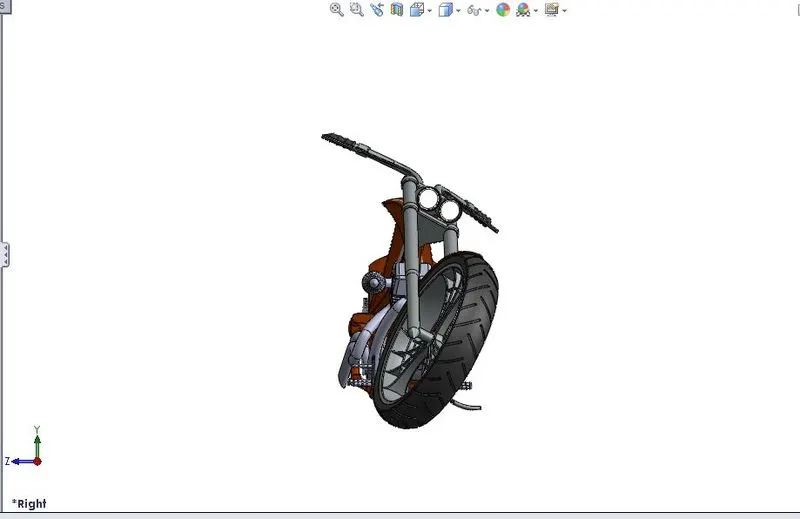
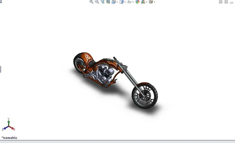
Assembled American chopper with different views
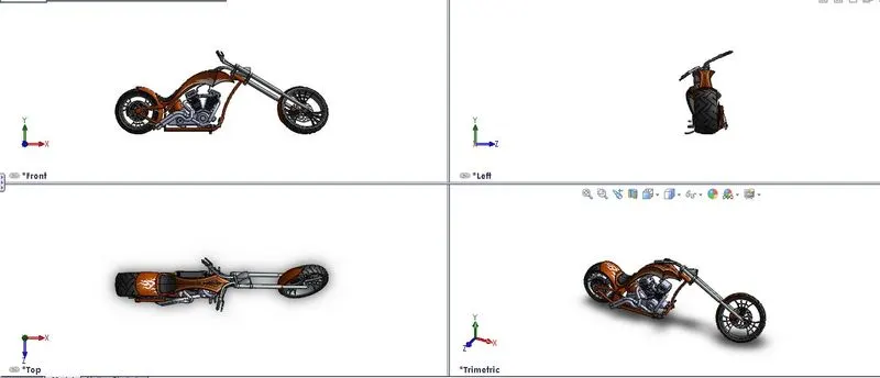
Front View
Top view
Side View
Isometric view
Camera setup View
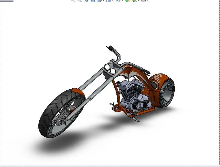
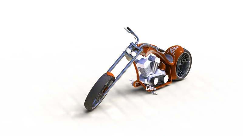
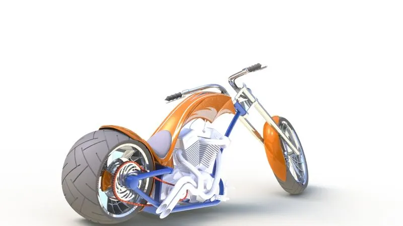
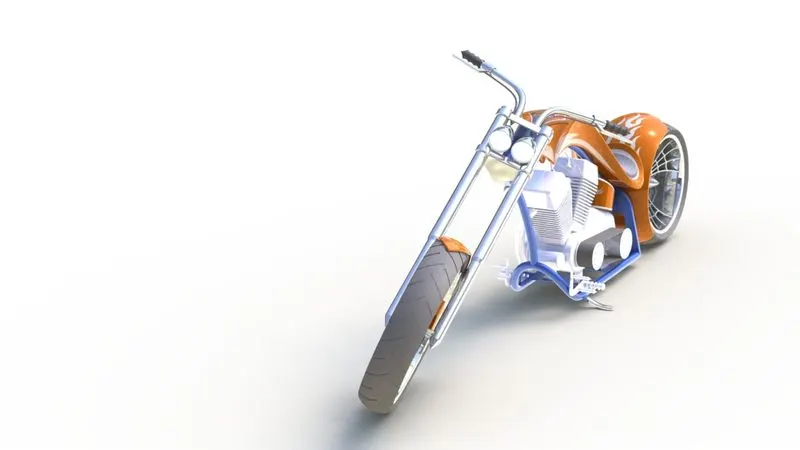
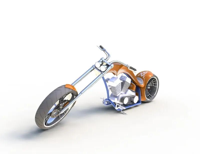
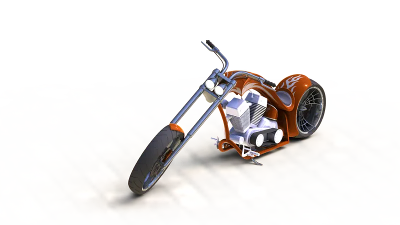
Rendering: - Rendering is the process of generating a photorealistic or non-photorealistic image from a 2D or 3D model by means of a computer program. The term "rendering" is also used to describe the process of calculating effects in a video editing program to produce the final video output. Rendering of American chopper is done by using photo view 360.
Some of the rendered images of American choppers are:
Visualization:- SOLIDWORKS Visualize allows us to leverage our 3D CAD data to create photo-quality content in the fastest and easiest way that we can from images to animations, interactive web content, and immersive Virtual Reality can bring our products to life. SOLIDWORKS Visualize is the “camera” for our CAD data. it is a separate render engine that is provided under solid work premium and professional. it helps us in creating rendered images of the SolidWorks model in a photorealistic environment.
some of the output of the SolidWorks visualization is shown below.
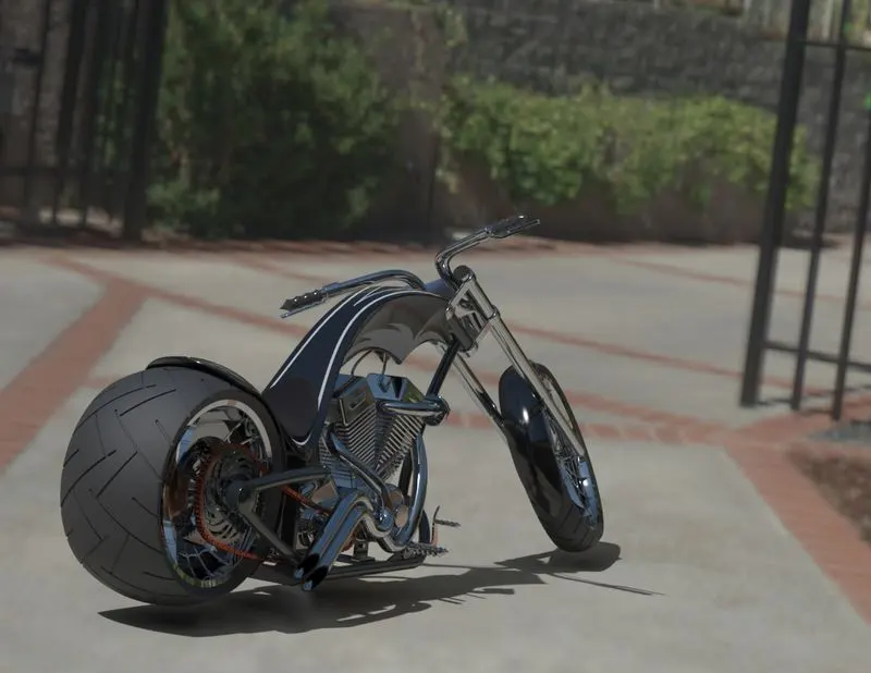
Fig. Abhishek_render_image_1
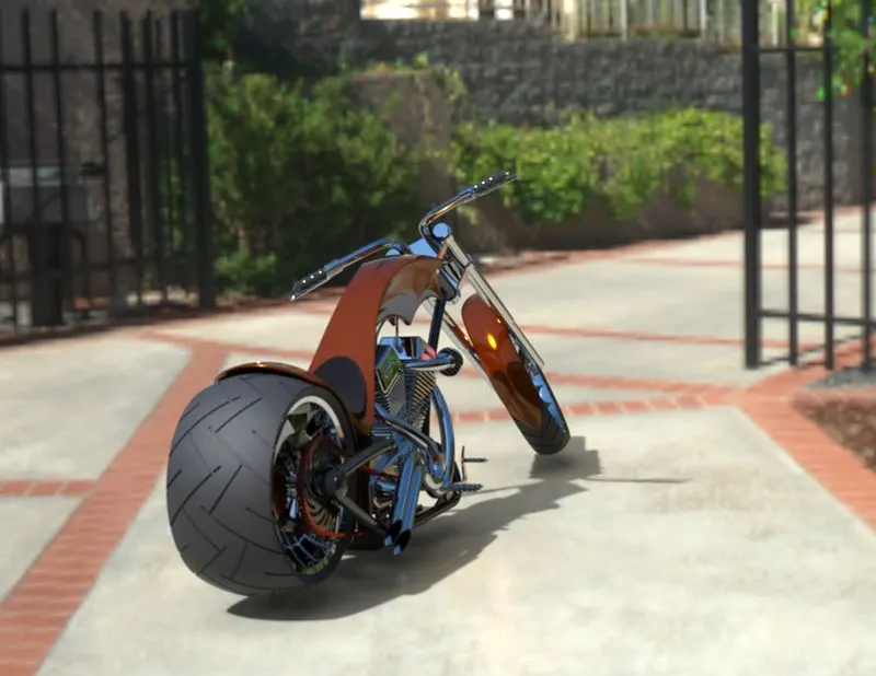
Fig. Abhishek_render_image_2
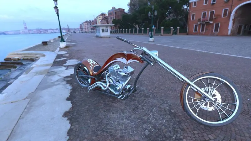
Fig. Abhishek_render_image_3
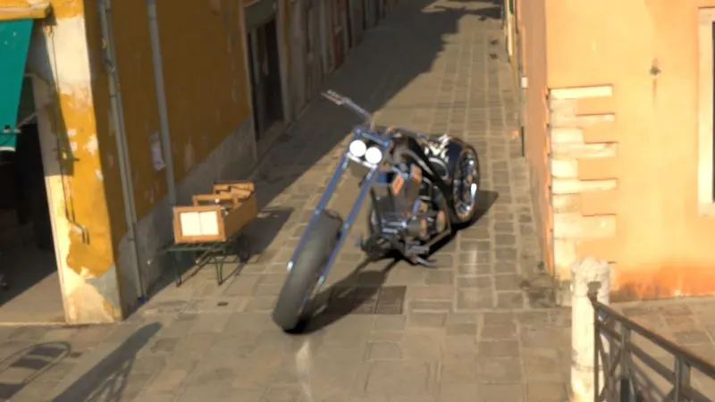
Fig. Abhishek_render_image_4
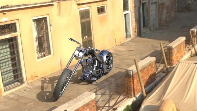
Fig. Abhishek_render_image_5
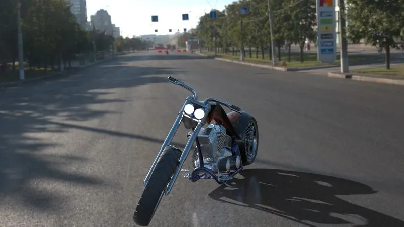
Fig. Abhishek_render_image_6
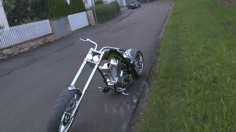
Fig. Abhishek_render_image_7
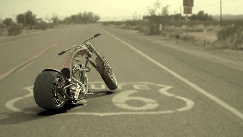
Fig. Abhishek_render_image_8
Conclusion: Thus design, assembly, rendering and visualization of the American chopper using SolidWorks was successfully completed. all the steps were followed and understood carefully.