Week 9 - Project - Master Section Development
MASTER SECTION
The Master section is nothing but the guidelines for the required design, which means the component is already designed, styled and concept. But in the master section, the reverse engineering is applied the component is located using the guided lines, according to the design required and then it is manufactured
Aim: To Design B-Pillar Through Master Section Development And Write a Detailed Report.
B-Pillar
- The B-Pillar Is The Central Pillar Of The Car. This Pillar Is a Sheet Metal Part Which Is Welded In The Biw Of The Car.
- The B-Pillar Trim Is Attached To The B-Pillar And Improves The Aesthetic Look Of The Car.
- Mostly The Trims Are Manufactured By The Injection Molding Process.
- The Design Of The B-Pillar Is Carefully Done To Make The Part Manufacturable And Usable In The Interior.
- While Manufacturing a Part Through Injection Molding a Lot Of Defects Can Occur On The Plastic Part Which Will Destroy The Look Of The Panel.
- The Design Has To be Made In Such a Way That All The Errors Can Be Rectified.
Concept Sketches:
- Concept Sketches Are Rough Idea Of Free Hand Sketch Obtained Through Styling Team And Will Be Used To Prepare The Model.
- It Is Usually Done Through Pen And Paper And Through The Painting Software.
- This Is Will Be Used To Generating The Concept For Preparing The Model By Incorporating Various Styles And Information Obtained Through The Stakeholders
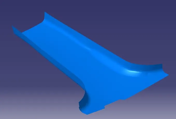
Class A Creation: After Finalizing The Concept The Sketches Are Usually Worked In Software Such As Auto-Desk Alias To Create Class-A Surface.
Tooling Axis:
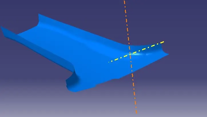
The Steps Followed In Creating Tooling Axis
- A Reference Point Is Created Along The Surface Zero And New Axis System Is Created The X Direction And Y Direction Along The Class A Were Used To Create the Tooling Direction.
- Finally, The Tooling Axis Is Created By Bisecting The Two Lines And It Is Published.
- Class A Surface As Input Using Surface Operation Commands Class B Is Developed
- The Tooling Axis Determines The Direction Of Class C Boundary Swept With Draft Direction.
- When Viewing From Tooling Direction Normal All The Parts That Are Drafted Should Be Visible So It Gives An Rough Idea To Determine Product Manufacturing In Injection Molding
- In B Pillar Model There Are Two Tooling Directions One On Main Tooling And the Other On Lifter Side That Is Used To Eject The Parts During Injection Modeling.
- Lifter Axis Is Used Because The Attachment Feature Is Bounded By Close Walls
B Surface Creation
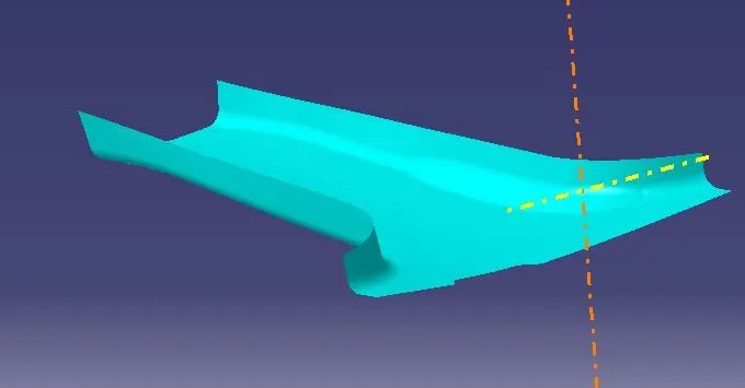
- The Next Step Is To Design B Surface For The Input Which Is Usually The Surface Where All Engineering Aspects And Support Creations Are Done.
- The B Surface Creation Is Performed Using Surface Operations In Catia Which Is An Offset From Class A With Dimension Proportional To The Thickness Of The Part In B Pillar Design
- The B Surface Is Offset 2mm From The Input Which Is The Thickness Of The Part
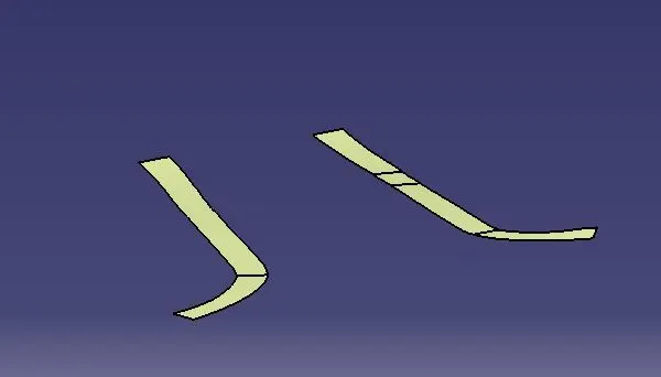
Flange Creation
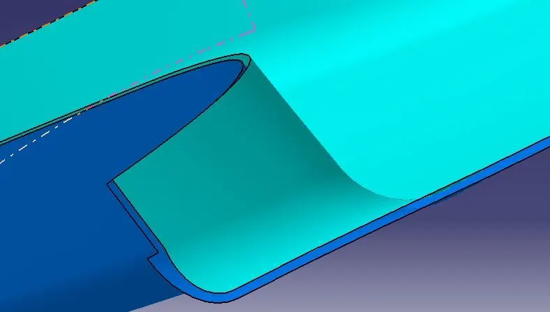
- According To The Master Section, The B-Pillar Has Flanges On Both Sides.
- The Flanges Have To Be Included In The Design And The A And B surfaces Have To Be Modified. The Surfaces Should Match The Master Section.
C Surface Creation
- The Next Step Is To From The C Surface Which Is An Intermediate Surface Between A And B And Is Used To Give The Closed Surface Appearance To The Design
- The C Surface Is Swept Using The Profile As Boundary Line Of Class A Which Is The Guide Curve With a Subtype Along Draft Direction.
- The Direction Of The Sweep Is The Tooling Direction Formed Earlier.
- The Draft Angle For The Sweep Operation Is Provided Which Is 3 Degree And the Surface Is Swept For Length Above The Thickness Of The Specified Part.
- The C Surfaces Must Be Drafted Outwards From The A-Side To Avoid The Parting Line Along The A Surface.
- The C Surface Is Refined Using Smooth Curve Options To Remove The Complexity And Patches Along The Swept Surface.
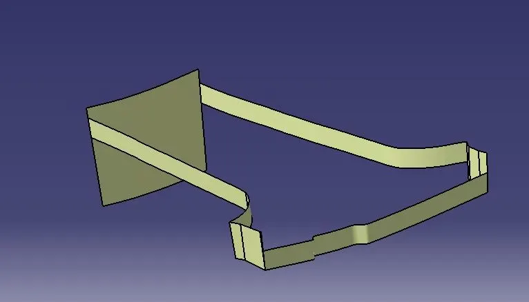
- Finally, The Class A And Class C Surfaces Are Joined Together And the Connexity Of Surfaces Should Be Less Than 0.003mm The Surfaces Are Merged. C Surface Merged With Class A.
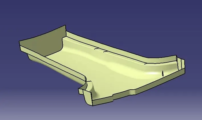
Closed Body Creation
- The Merged Surface Is Then Trimmed With B Surface To Form The Closed Surface.
- The Closed Surface Is Then Validated To Find The Irregularities Along The Edges And Imperfections Along The Edges Was Then Corrected Using Operation Like Extrapolate And Surface Trim
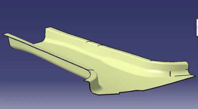
- This Closed Surface Is The Outer Skin And Finally The Part Is Formed By the Closed Surface In the Part Design Workbench
- The Final Part Is Measured To Validate The Uniform Thickness Of The Part Especially Along The Filleted Edges.
- The Uniform Thickness Ensures That The Part Created Doesn't Form Sink Mark And Flow Lines Along with Class A
Attachment Features
The Attachment Features Are The Fixation And Location Features That Fixes The Components The Common Attachment Features Used In B Pillar Are
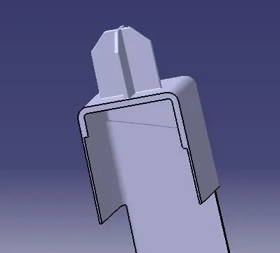
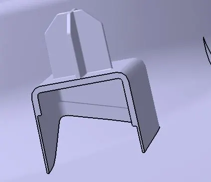
- Doghouse With 4 Way Locator
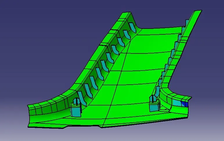
- Ribs
Doghouse Using The Master Section
- The Doghouse Is Created And Then Part Modelled Using Thickness Option
- The 4 Way Locator Is Formed Above The Dog House Which Locates The B Pillar Towards The Mating Surfaces
- The Dog House Design Rules Are The Thickness Of The Connecting Surface Towards B Side Should Be 40% Off The Main Thickness
- The Walls Are Drafted With Min 0.5 Degrees Along The Main Tooling Direction
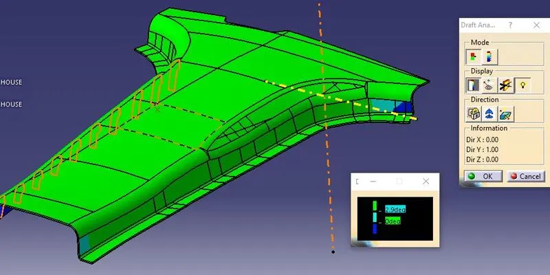
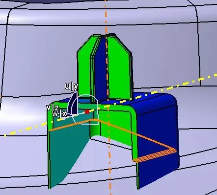
- The Attachment Feature Created Needs a Separate Tooling Axis To Clear The Part Hence a Lifter Axis Is Used
- The Surfaces That Are Cleared Along The Lifter Axis Are Also Given a Minimal Draft
- The Height Of The Attachment Walls Should Be a Minimum Of 3 Mm
- This Avoids The Plastic Defects On The B Side And Maintains The Texture Of A Side
- The Dog House With Four Way Locator Are Shown Below
Ribs
- Now, to strengthen the component, add some ribs on the B side.
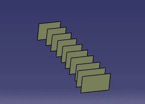
- For that, create a plane over a doghouse and create a sketch on it.
- The lines should be equidistant to 50mm as per rules for ribs.
- Extrude them to surfaces, broad enough that passes through the component as shown.
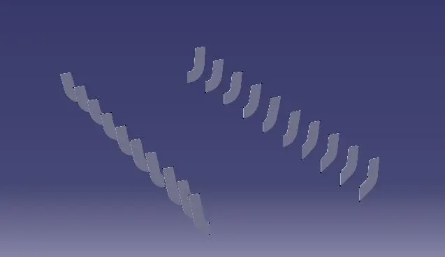
- Extract the sidewall and offset it to 20mm.
- Extrapolate the same and split the extruded surfaces.
- By this, we just limited the rib's size to 20mm away from the wall.
- Now, again extract the B surface and offset it to 10mm, because the maximum height of the rib can be 5 times that of the thickness (i.e. 2mm).
- Split the surfaces again with the offset surface.
- Thicken them in part workbench by 0.8mm because 0.4 times that of 2mm thickness a rib can be of.
- Union trim them with the main body
- Add draft of 0.5 degrees and fillet radius of 0.2mm.
- The final rib section is created.
- Follow the same method to create ribs on another side too.
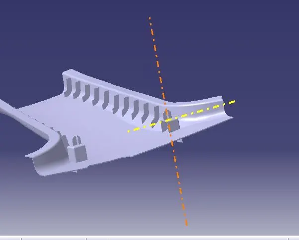
Draft Analysis Report
class A
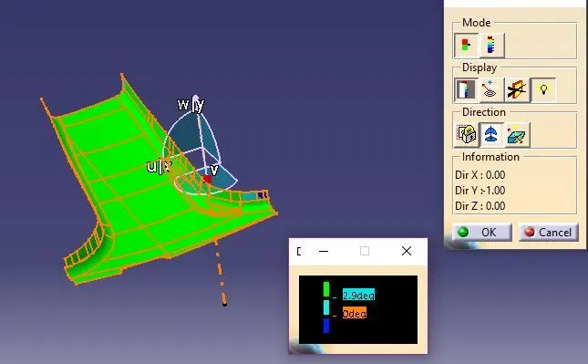
B pillar in main tooling Axis
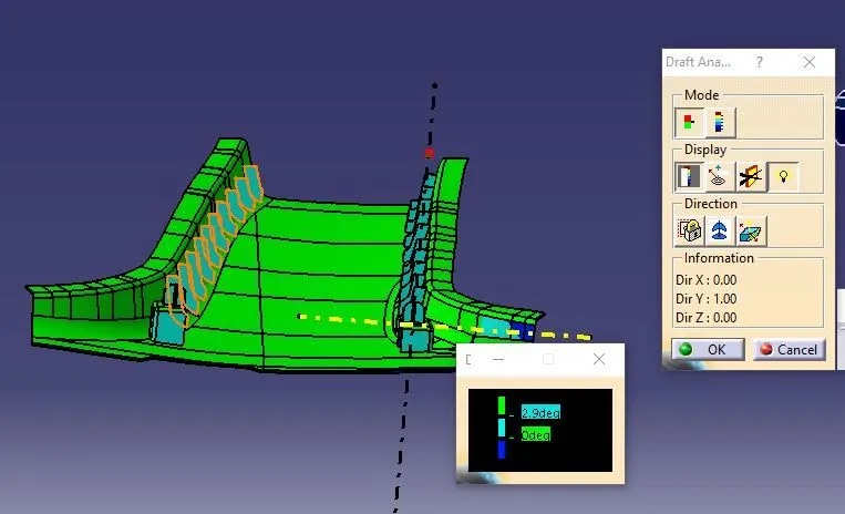
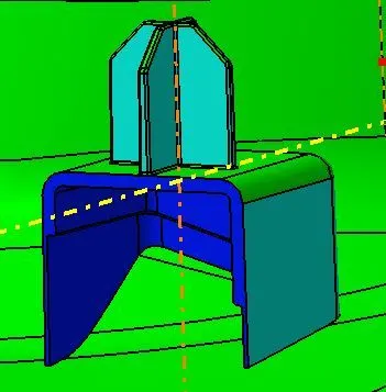
Draft analysis of dog house with 4-way locator along main tooling axis
Draft analysis of dog house with 4-way locator along lifter axis
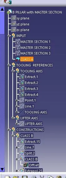
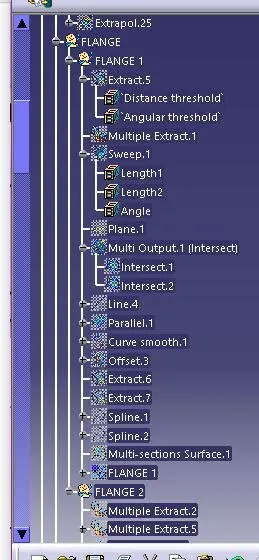
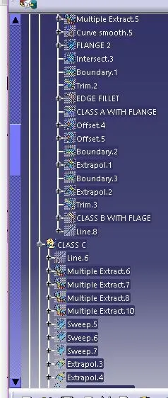
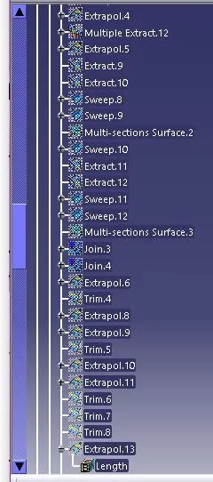
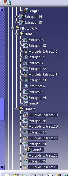
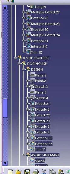
TREE STRUCTURE
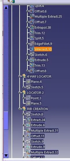
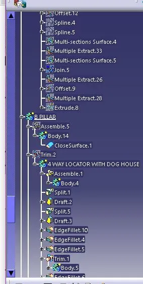
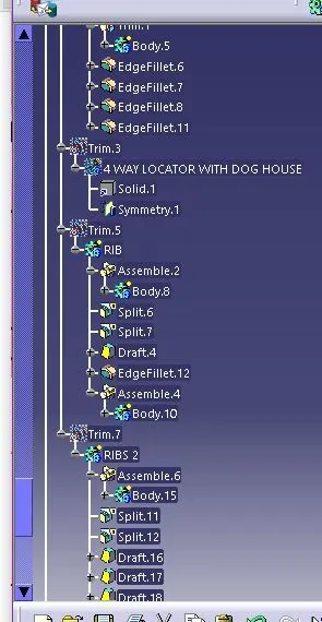
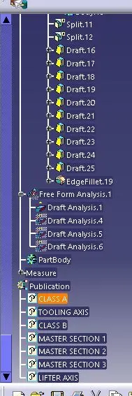
Conclusion
Thus a Tooling Axis Is Created And an Open Aesthetic Class A Surface Is Developed Into a Closed Surface With All Plastic Design Rules And a Final Part Body Is Created Out Of It In Catia Surface Work Bench. The Design Is Then Validated With Master Section And Understood The Use Of Master Section Development In Product Design Through Development Of B Pillar Cover Used In The Car Interiors.